Docking process on hybrid self-reconfigurable modular robots①
2017-03-28ShuaiLiguo帅立国
Shuai Liguo (帅立国)
*, Su Huizhe*, Zheng Liyuan*, Fei Yanqiong**(*School of Mechanical and Electrical Engineering, Henan Institute of Science and Technology, Xinxiang 453003, P.R.China) (**School of Mechanical Engineering, Shanghai Jiaotong University, Shanghai 200240, P.R.China)
Docking process on hybrid self-reconfigurable modular robots①
Shuai Liguo (帅立国)②
*, Su Huizhe*, Zheng Liyuan*, Fei Yanqiong**(*School of Mechanical and Electrical Engineering, Henan Institute of Science and Technology, Xinxiang 453003, P.R.China) (**School of Mechanical Engineering, Shanghai Jiaotong University, Shanghai 200240, P.R.China)
A novel hybrid self-reconfigurable modular robot is designed to finish the morphing action from line shape to hexagon shape. The robot is composed of many basic modules, each of which consists of a master module and a slave module in the shape of triangular prism. There are four connection ports on each basic module. For the master module there are two holes on each connection port, and for the slave one there are two pegs on each connection. The docking process between two neighboring basic modules is analyzed with a peg-in-hole mechanical structure. A small motion’s method is presented and the contact forces are derived. According to the force/moment, the pose of a motion module should be adjusted to make two neighboring modules align and finish the docking process. Finally, a simulation of 3 basic modules is shown to finish the morphing and docking process effectively. The system can finish the morphing task from the line shape to the hexagon shape.
self-reconfigurable robot, morphing, hybrid, module
0 Introduction
Self-reconfigurable modular robots (SMR) consist of a set of standardized electromechanical modules which can dynamically change their geometrical shape to complete different requirements of various tasks. Each module has the capability of intelligence, sense, communication and actuators. They are more versatile, flexible, and capable than fixed-morphology robots and work in unstructured and unpredictable environments, such as space and deep-sea exploration, rescue operations in earthquake areas.
SMR can be classified into three types: lattice-type, chain-type and hybrid type, where chain-type self-reconfigurable robots, such as the cubic modules (Polybot)[1], CONRO[2], have a higher degree of mobility than that of lattice-type systems. Lattice-type robots, on the other hand, can be easily self-reconfigured and are suitable for forming various static configurations, but have difficulty in generating motion, such as cubic structure (3-D self-reconfigurable mechanical system)[3], Fracta 3D[4], the two hemisphere module (ATRON)[5], Miche[6], the two semi-cylindrical module (M-TRAN)[7], UBot[8], the M-Cube[9,10]and M2SBot[11]. Roombots[12]have a hybrid chain/tree architecture. Each module has three degrees of freedom, two of them use a diametrical axis within a regular cube, and a third (center) axis of rotation connects with the two spherical parts. All three axes are continuously rotary.
In this paper, a hybrid SMR is designed, which consists of a master module and a slave module. There is a rotary motion between the master module and the slave module. The configuration of the SMR is described. There are four connection ports on each basic module, which can perform docking with the peg-in-hole method between two neighboring basic modules. With the small motion’s method, the contact forces between two docking modules are derived to adjust the pose of a motion module to finish the docking process.
1 Description of module structure
A hybrid self-reconfigurable modular robot is proposed. The basic module in the hybrid self-reconfigurable modular robot is composed of a master module and a slave module both are in the shape of triangular prism and each has three connection sides. The slave module is fixed to the master module on the fixed connection port and can rotate about the master module. Each module has two other connection ports: the master module, having two holes on each connection port and the slave module with two pegs on each connection port (Fig.1). Each peg has three beads in a lock system, which can lock the connection when two pegs of the slave module are inserted into two holes of the master module. Then, two basic modules are connected to each other (Fig.2(a)). The connection ports can
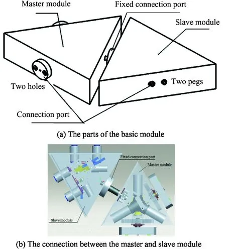
Fig.1 The basic module

Fig.2 Two basic modules
rotate along their axes. Basic module 2 rotates 180° along the connection port of basic module 1. The chart is shown in Fig.2(b).
2 Analysis of docking process
2.1 Docking process
For self-reconfigurable modular robots, the successful docking action consists of at least three integrated stages. First, the module is moved on a given trajectory, so that two modules are positioned close to each other. Second, two modules are aligned to each other to satisfy the constraints of the docking. Third, after two docking modules are aligned (Fig.3(a)), the pin and beads move, and the shell of the peg moves. Two pegs are inserted into two holes (Fig.3(b)). When the beads arrive at the position of the groove in the hole, the shell of the peg pushes the beads. Then, beads stick in the hole. So the pegs are locked in the holes (Fig.3(c)). The disconnection is the reverse process of the connection. When an existing connection is disconnected, the latching mechanism is released by pegs.

Fig.3 Docking process of two pegs and two holes
For the hybrid self-reconfigurable robot, the connection process consists of basic module i inserting into basic module j which is a dual peg-in-hole process. The geometric model of the dual peg-in-hole is shown in Fig.4: the radii of the left peg, right peg, left hole, and right hole are rP1, rP2, rH1and rH2, respectively. D or DP represents the distance between the axes of the pegs, and DH represents the distance between the axes of the holes.
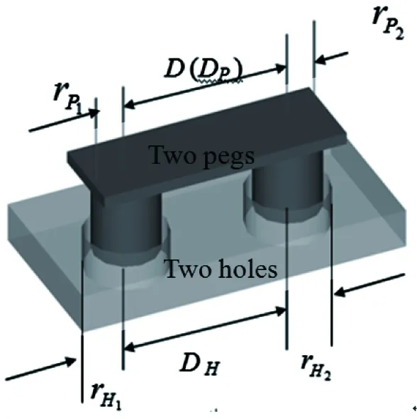
Fig.4 Geometrical models of connection
2.2 States of constraint
In the study, two dimensional problems are discussed. The geometrical models of two pegs and two holes in basic modules i and j are shown in Fig.5. There is tilt angle θ between two docking modules. For the boundary state of the connection, its geometrical constraint is When θ is more than θ0, two modules cannot align. Pegs cannot be inserted into holes and cannot finish the connection action. So, the tilt angle must be adjusted to make θ<<θ0and avoid sticking. When θ<θ0, because of the uncertainty of geometry and control, contact states exist during two basic modules connection. From the geometrical constraints, it is known that there are at most two-point contact states in the left peg and the left hole (Fig.5). The geometrical constraint is For each basic module
(1)
hi1sinθ+2rPj1cosθ=2rHi1
(2)
rPj1=rPj2, rHi1=rHi2
(3)
Thus, the geometrical constraint of the two-point contact state in the right peg and the right hole is
hi2sinθ+2rPj2cosθ<2rHi2
(4)
Then, there are at most three-point contact states in two basic modules’ connection. The pose of the motion module should be adjusted and the tilt angle should be reduced to avoid contact states appearing.
Where hi1is an insertion depth of the left peg (module Mj) into the left hole (module Mi) and hi2is an insertion depth of the right peg (module Mj) into the right hole (module Mi). The left peg of module Mj has a radius of rPj1, whereas the right peg of module Mj has a radius of rPj2. Radii of the left hole in module Mi and the right hole in module Mi are rHi1and rHi2, respectively. θ and θ0are angles between the axis of a peg and that of a hole. Di, Djrepresent the distance between the peg’s axis and the hole’s axis of module Mi, module Mj, respectively.
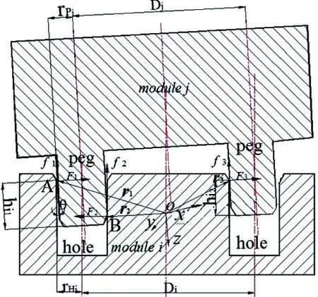
Fig.5 The geometrical model of the connection in basic modules i and j in two dimensions
2.3 Contact forces of connection
The coordinate system (oxyz) is set up at the center of each module (y=z(x) (Fig.5) in which vectors rgof the contact points relative to origin o can be obtained, where g represents the contact points, g=1,2,3. The wrenches of the contact cases are described as follows
(5)
(6)
fg=μFg
∑(Fg+fg)+F=0
约有10%的宝宝1岁之后状况仍未改善,此后更容易发生面部不对称甚至颈椎弯曲。这时就要根据个人情况,考虑手术治疗了。手术目的是将颈部受累肌肉的部分切除,从而改善症状。当然提到手术就要考虑到术前评估,手术、麻醉方式以及术后看护等具体问题。因此,动手术之前一定先跟医生沟通好。
(7)
∑(Mg+Mμg)+M=0
(8)
In two dimensions, when there are three contact points (Fig.5), the formed system of equations is redundant. The unknown variables are four, while the available equations are three. To overcome this problem, a small motion’s method about small motions of the peg around the contact points[13]is improved.
For contact point B on the left peg-in-hole (Fig.5), the angle between the force vector F2and the x-axis is 180°-θ. Let the direction of the k-axis be the same as that of the force vector F2. The k’-axis is vertical to k-axis. A translation δkalong the k-axis and a rotation is δφ about the k’-axis due to δs. δsis a unit displacement at the contact point.
δk+δφ·H=δs
(9)
The following equations can be obtained
F2·δs=Fk·δk+Mk′·δφ=-(Fxcosθ+Fzsinθ)·δk+(Mxsinθ-Mzcosθ)·δφ
(10)
(11)
Solving Eqs(9)-(11), F2can be obtained

(12)
where H is the length of the connection peg, gtkis the gain of the sensor in tension in the k-axis direction and gTk′is the gain of the sensor in torsion in the k’-axis direction.
Thus, the expressions of the contact forces can be shown simply. From the above expressions, it is known that the docking process of two basic modules is a complex multiple peg-in-hole process. According to the force/moment, the pose of a motion module should be adjusted to make two modules align and finish the docking.
It can be concluded that when θ>θ0, two basic modules cannot be aligned, the pegs cannot be inserted into the holes, and thus the docking process cannot be accomplished. Therefore, the tilt angle must be adjusted to θ<<θ0to avoid sticking. When θ<θ0, contact states exist during two modules connection because of the uncertainty of geometry and control. Thus, sensors must be used to adjust the orientation of each basic module to finish the docking action to obtain different configurations.
3 Simulation
Based on the rotary motion and the docking process between the master module and the slave module, the morphing action can be performed with ADMAS.
A simulation of 3 basic modules is shown to finish the morphing action from the line shape to the hexagon shape in Fig.6. The master module weighs 0.31kg, the slave module weighs 0.54kg and the speed of each joint is v=5d/s. In Fig.6(a), the master modules connect to the slave modules with fixed connection ports (joint 1, joint 3 and joint 5). Basic module 1 connects to basic module 2 with connection port 1 (joint 2). Basic module 2 connects to basic module 3 with connection port 2 (joint 4), resulting in a line shape. In Fig.6(b), basic module 3 rotates 180° along connection port 2. In Fig.6(c), basic module 1 and the slave module of basic module 2 rotate -180° along fixed connection port 2 (the joint 3). In Fig.6(d), basic module 1, basic module 2 and the slave module of basic module 3 rotate 180° along fixed connection port 3 (the joint 5). In Fig.6(e), the pose of basic module 1 is adjusted to make the contact forces zero. Two pegs of basic module 1 are inserted into two holes of basic module 3 and the docking process is finished to obtain the hexagon shape. The morphing process is finished. The output torque of joint 2 and the kept torques of joint 1, joint 3, joint 4 and joint 5 are shown inFig.7(a),Fig.7(b).
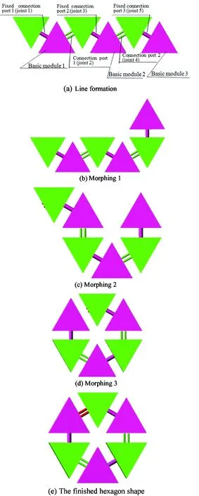
Fig.6 The morphing and docking process of 3 basic modules
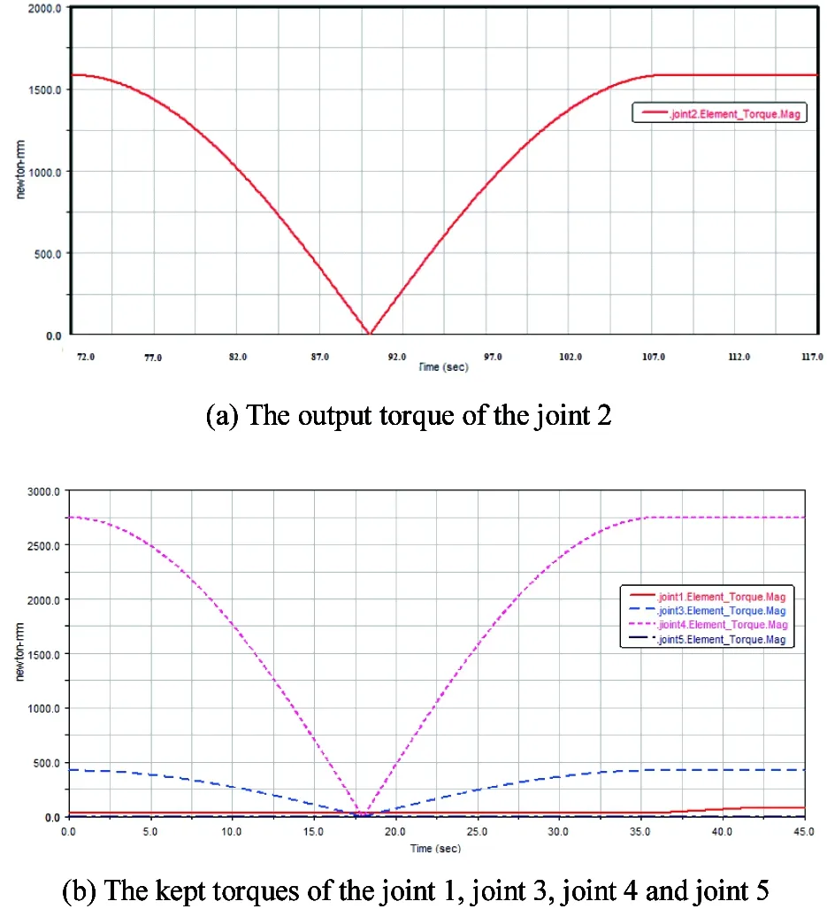
Fig.7 The torque of each joint
Fig.7 shows that, in the process of docking, the torque of the five joints is changing with time. At the beginning, joint 2 and 4 are 1600N·mm and 2700N·mm respectively, while other three joints are presented almost 0 N·mm as shown in the Figure. Also, it can be seen that joint 1, joint 3, joint 4 and joint 5 have almost the same variation trend with the time, and reach 0 at 18s or so, while there is a difference between joint 2 and other joints. When the process of docking finishes, the hexagon shape is in a
new stable condition as that of the line shape. Consequently, the joints between two adjacent modules are almost bearing the same torque with those of the initial condition.
4 Conclusions
In this paper, a hybrid self-reconfigurable modular robot is proposed. Each basic module consists of a master module and a slave module. There is a rotary motion between the master module and the slave module. With the peg-in-hole method, the neighboring basic modules can perform docking action. The docking process and the contact forces between two neighboring basic modules are analyzed with the small motion’s method in detail. The tilt angle between two basic modules must be adjusted to θ<<θ0to avoid sticking. At last, a simulation of morphing process 3 basic modules is shown and the torque of each joint is presented. The hybrid self-reconfigurable robot can finish the morphing and docking process from the shape of line to the shape of hexagon.
[1] Yim M, Zhang Y, Roufas K, et al. Connecting and disconnecting for chain self-reconfiguration with PolyBot . IEEE/ASME Transactions on Mechatronics, 2002, 7: 442-451
[2] Castano A, Behar A, Will P. The conro modules for reconfigurable robots. IEEE/ASME Transactions on Mechatronics, 2002, 7(4): 403-409
[3] Murata S, Yoshida E, Kurokawa H, et al. Self-repairing mechanical systems. Autonomous Robots, 2001, 10: 7-21
[4] Murata S, Kurakawa H, Yoshida E, et al. A 3-D self-reconfigurable structure. In: Proceedings of IEEE International Conference on Robotics and Automation, Victoria, Canada, 1998. 432-439
[5] Christensen D J, Stoy K. Selecting a meta-module to shape-change the ATRON self-reconfigurable robot. In: Proceedings of IEEE International Conference Robotics and Automation, Orlando, USA, 2006. 2532-2538
[6] Gilpin K, Kotay K, Rus D, et al. Miche: modular shape formation by self-disassembly. International Journal of Robotics Research, 2008, 27(3-4): 345-372
[7] Kurokawa H, Tomita K, Kamimura A, et al. Distributed self-reconfiguration of M-TRAN III modular robotic system. The International Journal of Robotics Research, 2008, 27(3-4): 373-386
[8] Zhao J, Wang X L, Jin H Z, et al. Automatic locomotion generation for a UBot modular robot-towards both high-speed and multiple patterns. International Journal of Advanced Robotic Systems, 2015, 12(32): 1-10
[9] Fei Y Q, Zhao X F. Design and dock analysis for the interactive module of a lattice-based self-reconfigurable robot. Robotics and Autonomous Systems, 2007, 55(2): 87-95
[10] Fei Y Q, Zhu Y L, Xia P. Analysis on self-morphing process of self-reconfigurable modular robot. International Journal of Advanced Robotic Systems, 2009, 6(3): 215-222
[11] Sun X Y, Ge W M, Wang X F, et al. A reconfiguration approach for self-reconfigurable modular robot using assisted modules. In: Proceedings of 2015 IEEE International Conference on Mechatronics and Automation, Beijing, China. 1436-11441
[12] Sproewitz A, Pouya S, Bonardi S, et al. Roombots: reconfigurable robots for adaptive furniture. IEEE Computational Intelligence Magazine, 2010, 5(3): 20-32
[13] Tsaprounis C J, Aspragathos N. Contact point identification in robot assembly strategies under uncertainty. Robotica, 1998, 16: 679-690
Shuai Liguo, born in 1968. He received his M.S.degree and Ph.D degree in School of Instrument Science & Engineering of Southeast University in 1998 and 2001,respectively. He also received his B.S. degree from Xi’an JiaoTong University in 1991. His research interests include the intelligent robots, the technology of tactile display and the virtual reality technology.
10.3772/j.issn.1006-6748.2017.01.010
①Supported by the National Natural Science Foundation of China (No. 61175069, 51075272, 51475300).
②To whom correspondence should be addressed. E-mail: liguo.shuai@126.com Received on Feb. 25, 2016
猜你喜欢
杂志排行

High Technology Letters的其它文章
- Research on logistics domain-oriented cloud resource management model and architecture①
- A clustered routing protocol based on energy and link quality in WSNs①
- A GA approach to vehicle routing problem with time windows considering loading constraints①
- Integrated optimal method for cell formation and layout problems based on hybrid SA algorithm with fuzzy simulation①
- A study on TCP performance of crowdsourced live streaming①
- Coupling methods of global climate models and regional climate models①