Sufficiently diffused attachment of nitrogen arc by gasdynamic action
2017-01-06WenxiaPanLewenChenXianMengYongZhangChengkangWu
Wenxia Pan,Lewen Chen,Xian Meng,Yong Zhang,Chengkang Wu
The State Key Laboratory of High Temperature Gas Dynamics,Institute of Mechanics,Chinese Academy of Sciences,Beijing 100190,China
Sufficiently diffused attachment of nitrogen arc by gasdynamic action
Wenxia Pan∗,Lewen Chen,Xian Meng,Yong Zhang,Chengkang Wu
The State Key Laboratory of High Temperature Gas Dynamics,Institute of Mechanics,Chinese Academy of Sciences,Beijing 100190,China
H I G H L I G H T S
·Diffused attachment of pure nitrogen arc on water-cooled anode surface.
·Arc channel design with a flow-restrictor and downstream expansion.
·Suitable combination of working parameters and the structural features of the plasma generator.
·Mechanism of arc dispersion through thermal blocking and downstream expansion.
A R T I C L E I N F O
Article history:
Received 16 July 2016
Received in revised form
5 September 2016
Accepted 8 September 2016
Available online 20 September 2016
Pure nitrogen arc
Diffused arc root attachment
Gas dynamic expanding action
Arc channel structure
Working parameter
For realizing diffused anode attachment in pure nitrogen arcs, a special arc plasma generator was designed and combined with suitable working parameters such as gas flow rate and arc current. The anode has a flow-restrictor channel of 2.8mmdiameter and downstream expansion half-angle of 8°,withthepurpose of creating a dispersed nitrogen-arc column by strong gasdynamic expansion effect.Results show that, when thermal blocking condition existed in the flow restrictor and the cathode cavity pressure was higher than that in the exit chamber by at least 9 kPa,the action due to gasdynamic expansion could be much stronger than the self-magnetic contraction effect of the arc and the nitrogen arc column could be effectively dispersed to form a sufficiently diffused attachment on the water-cooled anode surface.
©2016 The Author(s).Published by Elsevier Ltd on behalf of The Chinese Society of Theoretical and Applied Mechanics.This is an open access article under the CC BY-NC-ND license(http:// creativecommons.org/licenses/by-nc-nd/4.0/).
Thermal plasmas are widely used in industries and aeroastronautic exploration.Direct-current(DC)non-transferred arc is a main type of their production,with the gas-discharge arc acting as the current path between the cathode and anode. Ordinarily, the arc attachment is highly constricted at the water-cooled electrode surface,and current density reaches order of 108A/m2.Thus,the working life limited by local erosion has always been a bottleneck in the effective utilization of these plasma generators.During the past decades,various attempts to increase lifetime by reducing electrode erosion have never been interrupted.These include large-scale jumping of the attachment point[1,2];insertion of inter-electrode sections to increase arc length for higher voltage and lower current[3];use of multi electrode sets[4];using external magnetic field to cause rapid circumferential motion of the arc attachment along the electrode surface[5,6].All these methods have the common character of causing the erosion to be spread over a larger area so that deep erosion at local spots could be reduced and working life could be lengthened,but they cannot changetheattachmentmodeoflocalhighcurrent-densityspotson the cooled electrode surface.
The basic thinking of this work is given as follows:through a suitable combination of generator structure and working parameters of the plasma,adjust the flow conditions in the arc channel so as to create a nitrogen arc column with larger volume and lower current density long before it reaches the anode surface, thus basically avoiding the formation of the much constricted anode attachment and local deep erosion.
The structure of the self-designed DC non-transferred arc plasma generator is shown in Fig.1 schematically.Its main feature is the structure of the anode,with a small arc channel upstream near the tip of the cathode,called the flow-restrictor,and the downstream passage has an expansion half angle of 8°.Choosing suitable arc current and gas flow rate causes the arc root unable to be attached to the anode surface in the cathode cavity,but the arc column,passing through the flow-restrictor in a thermal blocking or choking state,expands under the gasdynamic action,reaching the anode surface downstream the restrictor in a dispersed state, forming diffused attachment at low current density.
Pure nitrogen was used as the plasma working gas at a flow rate of 4–13 standard liter per minute(slm).For comparison with former experiments using nitrogen–argon mixtures,observations with these mixtures were also made.The generator was fixed on the same chamber as used in Refs.[6,7].The environmentalpressure was first reduced to about 15 Pa with a vacuum pump, then the working gas was filled in and the arc ignited.The environmental pressure(PEshown in Fig.1)was controlled during experiment at 5–85 kPa by the valve between the chamber and the vacuum system.Pressure in the cathode cavity(PC)was measured with transducer connected to the oscilloscope,and the environmental pressure was measured with resistance and thinfilm pressure gages.The arc current producing the plasma was 80–110 A.A self-designed copper mirror with weak-reflecting material imbedded at the center part was used to observe condition of the arc root attachment on the anode surface,as shown in Fig.1,recorded by intensified charge coupled device (ICCD)camera.The purpose of the weak-reflecting material at the center part of the copper mirror is to reduce the reflection of the strong emission light from the high current-density arc column in the restrictor channel and near cathode portion,to enable clear observation of the light signal from the diffused attachment of the arc root in the expansion part of the anode.The state of the plasma jet was recorded with camera and video recorder.

Fig.1.Schematic drawing of the arc plasma generator and the setting for arc root attachment picture.
Figure 2 shows the cathode cavity pressure variation with pure nitrogen at different gas flow rate,arc current,and environmental pressure.The dashed line in the figure shows the variation of cathode cavity pressure with environmental pressure at fixed gas flow rate of 4 slm and arc current of 110 A.When environmental pressure is lower than 30 kPa,its variation does not affect the cathodecavitypressurewhichkeepsatabout41kPa.Thisindicates thermal choking occurred in the flow-restrictor,and the cathode cavity pressure is determined only by the gas flow rate and arc heating condition.When environmental pressure is higher than 30 kPa,i.e.,when the ratio of cathode cavity to environmental pressures becomes lower than about 1.4,the cathode cavity pressure changes with rise in environmental pressure,and their difference gradually decreases.At 80 kPa environmental pressure, the cathode cavity pressure was 89 kPa.This shows that thermal choking no longer existed in the flow-restrictor,but some thermal blockage effect still existed. All other data points in this figure were taken at pressure ratios higher than those shown by the sloped line in the figure.
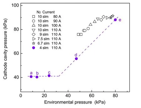
Fig. 2. Cathode cavity pressure changes with the arc current and gas flow rate, and also changes with the environment pressure of the plume ejecting in. The solid markers a,b,c,d,e correspond to pictures a,b,c,d,e in Fig. 3.
Figure 3 shows the arc root attachment conditions on cooled anode surface taken with ICCD,corresponding to conditions marked by‘a’to‘e’in Fig.2.The dark area at the center reflects the strong light radiation from the arc column by the weakly-reflecting material at the center of the copper mirror. It can be seen that,in these experiments the arc roots are all sufficiently diffused in axi-symmetric attachments at large area, clearly different from the constricted attachments on the anode surface in arcs containing nitrogen in Refs.[6,7].Regardless of variation in environmental pressure or whether thermal choking occurred in the flow-restrictor due to arc heating,there is no apparent difference in the arc root attachment area or distribution on the expanding portion of the anode.From the dimensions of the anode structure and the projection relationship from the copper mirror,it was analyzed that the arc root attachment area was located mainly from the exit of the flow-restrictor to an axial distanceabout17.3mmdownstream,withan areaabout287mm2ontheexpandingsurfaceoftheanode.Theaveragecurrentdensity attheattachmentwasestimatedtobe3.8×105A/m2,muchlower than the ordinary value of~108A/m2in constricted nitrogen arc root on water-cooled anode surfaces.Under the conditions of generator structure and working parameters in Refs.[6,7],diffused arc root attachments were only observed in pure argon,and became constricted if only 5%nitrogen was mixed in.

Fig.3.ICCD pictures of the arc root attachment correspond to the solid marker conditions indicated in Fig.2.The exposure time is all 5µs and the circle in each picture is added to indicate the nozzle exit edge.

Fig.4.Plasma jet behavior corresponding to the solid marker conditions indicated in Fig.2.
In experiments[6,7],diffused arc attachment was only observed in pure argon,and small addition of nitrogen clearly created constricted arc root attachment and electrode erosion.To show more clearly the dispersion effect of the arc column and the diffused attachment,Fig.5(a)gives the ICCD picture of the arc root attachment in pure argon at 6.6 slm flow rate and 80 A arc current. Usingthesameanalysismethoddescribedabove,itcanbededuced thatin thepresent caseof pureargon,the arcattachment wasatan axial distance about 18.7 mm downstream from the exit of flowrestrictor,covering an area of about 321 mm2.Figure 5(b)shows that the mixture of 3 slm argon and 10 slm nitrogen has an even wider area of diffused attachment of about 463 mm2covering an axial distance of about 23.8 mm,at an arc current of 80 A.That is, with addition of argon gas and at higher flow rates,there will be even larger area of diffused arc root attachment.
Figure 6 shows the nitrogen arc voltage variation with(a)arc current and(b)gas flow rate.At arc current of 110 A,the arc voltage rises appreciably with increasing gas flow rate.This is the common behavior of non-transferred arc plasma generators. However,the variation of arc voltage with changing arc current shows complicated situation,and does not have a common rule. This could be because of the special design of this generator with its changed dimensions of the arc channel,which causes different effects on various sections of the arc.At a nitrogen flow rate of 10 slm,the arc voltage falls with increasing arc current.But at a flow rate of 4 slm,there is no clear trend of arc voltage variation with changing arc current,but shows large irregular variations.

Fig.5.ICCD pictures of the arc root attachment with exposure time 10µs and the circle in each picture is added to indicate the nozzle exit edge.(a)Pure argon gas at 6.6 slm,80 A,6.9 kPa environment pressure,and 55 kPa cathode cavity pressure; (b)3 slm argon and 10 slm nitrogen mixture at 80 A,46 kPa environment pressure and 88 kPa cathode cavity pressure.
The points a to e in this figure correspond to those in Fig.2, where the environmental pressure at the generator exit varied over a wide range between 9 and 81 kPa.Generally speaking,arc voltage is directly proportional to current density and arc length, but inversely proportional to electric conductivity of the arc.All thesefactorsareaffectedbyarccurrent,gaspressure,gasflowrate, and the state of contraction or dispersion of the arc.
Experimental results and analysis show that the pure nitrogen arc column can be effectively dispersed to form diffused attachment at the water-cooled anode surface,in the present generator design and working parameter range.High gas flow rate and addition of argon will be helpful in enhancing the diffused area of arc root attachment.
Acknowledgment
This work is supported by the National Natural Science Foundation of China(11575273).
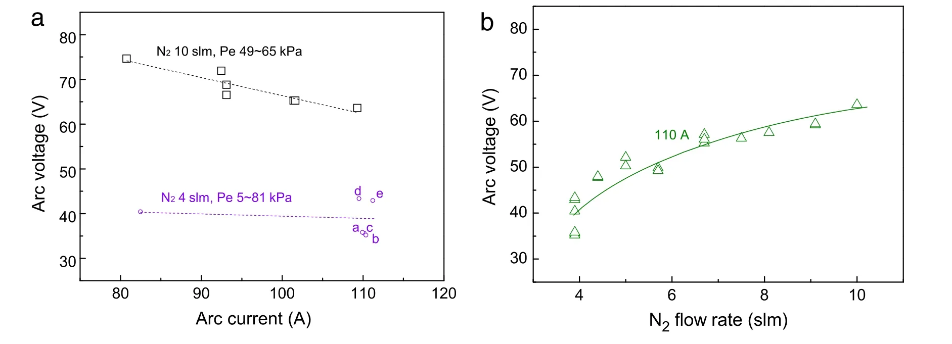
Fig.6.Variation of arc voltage as the change of(a)arc current and(b)gas flow rate of pure nitrogen gas.
[1]J.P.Trelles,E.Pfender,J.V.R.Heberlein,Modelling of the arc reattachment process in plasma torches,J.Phys.D:Appl.Phys.40(2007)5635–5648.
[2]X.Sun,J.V.R.Heberlein,Fluid dynamic effects on plasma torch anode erosion, J.Therm.Spray Technol.14(2005)39–44.
[3]G.Russo,F.De Filippis,S.Borrelli,et al.,The SCIROCCO 70-MW Plasma Wind Tunnel:A New Hypersonic Capability,Advanced Hypersonic Test Facilities, Frank Lu,Dan Marren(Eds.),AIAA,2002,pp.315–351.
[4]J.Schein,J.Zierhut,M.Dzulko,et al.,Improved plasma spray torch stability through multi-electrode design,Plasma Phys.47(2007)498–504.
[5]L.C.Li,W.D.Xia,H.L.Zhou,et al.,Experimental observation and numerical analysis of arc plasmas diffused by magnetism,Eur.Phys.J.D 47(2008) 75–81.
[6]W.X.Pan,X.Meng,T.Li,et al.,Comparative observation of Ar,Ar-H2and Ar-N2DC arc plasma jets and their arc root behavior at reduced pressure,Plasma Sci. Technol.9(2007)152–157.
[7]W.X.Pan,T.Li,X.Meng,et al.,Arc root attachment on the anode surface of arc plasma torch observed with a novel method,Chin.Phys.Lett.22(2005) 2895–2898.
[8]Z.Y.Guo,W.H.Zhao,Arc and Thermal Plasma,Science Press,Beijing,1986(in Chinese).
∗Corresponding author.
E-mail address:wxpan@imech.ac.cn(W.Pan).
http://dx.doi.org/10.1016/j.taml.2016.09.001
2095-0349/©2016 The Author(s).Published by Elsevier Ltd on behalf of The Chinese Society of Theoretical and Applied Mechanics.This is an open access article under the CC BY-NC-ND license(http://creativecommons.org/licenses/by-nc-nd/4.0/).
*This article belongs to the Fluid Mechanics
杂志排行

Theoretical & Applied Mechanics Letters的其它文章
- A large eddy simulation of flows around an underwater vehicle model using an immersed boundary method
- Modelling windwave driven by typhoon Chan-Hom(201509)in the East China Sea
- Numerical simulation of Gurney flap on SFYT15thick airfoil
- On transition of type V interaction in double-wedge flow with non-equilibrium effects
- On the role of piezoelectricity in phonon properties and thermal conductivity of GaN nanofilms
- Coriolis effect on responses of rotating thin piezoelectric hollow cylinder