Laser cut hole matrices in novel armour plate steel for appliqué battlefield vehicle protection
2016-11-28DanielTHOMAS
Daniel J.THOMAS*
Engineering Manufacturing Centre,College of Engineering,Swansea University,Swansea,UK
Available online 27 July 2016
Laser cut hole matrices in novel armour plate steel for appliqué battlefield vehicle protection
Daniel J.THOMAS*
Engineering Manufacturing Centre,College of Engineering,Swansea University,Swansea,UK
Available online 27 July 2016
During this research,experimental rolled homogeneous armour steel was cast,annealed and laser cut to form an appliqué plate.This Martensitic–Bainitic microstructure steel grade was used to test a novel means of engineering lightweight armour.It was determined that a laser cutting speed of 1200 mm/min produced optimum hole formations with limited distortion.The array of holes acts as a double-edged solution,in that they provide weight saving of 45%,providing a protective advantage and increasing the surface area.Data collected were used to generate laser cut-edge hole projections in order to identify the optimum cutting speed,edge condition,cost and deformation performance.These parameters resulted in the generation of a surface,with less stress raising features.This can result in a distribution of stress across the wider surface.Provided that appropriate process parameters are used to generate laser cut edges,then the hardness properties of the surface can be controlled.This is due to compressive residual stresses produced in the near edge region as a result of metallurgical transformations.This way the traverse cutting speed parameter can be adjusted to alter critical surface characteristics and microstructural properties in close proximity to the cut-edge.A relationship was identified between the width of the laser HAZ and the hardness of the cut edge.It is the thickness of the HAZ that is affected by the laser process parameters which can be manipulated with adjusting the traverse cutting speed.
©2016 The Author.Production and hosting by Elsevier B.V.on behalf of China Ordnance Society.This is an open access article under the CC BY-NC-ND license(http://creativecommons.org/licenses/by-nc-nd/4.0/).
Armour steels;Defence systems;Steel processing;Armour engineering
1.Introduction
Adaptive armour steel plate is a vital component towards providing a protective advantage for battlefield vehicles[1]. Currently,armour plate steels are an important component towards providing an energy absorbing barrier and countering threats from high energy projectiles,munitions and improvised explosive devices.Steel processing conditions and final microstructural and mechanical properties are critical factors that influence the characteristics of armour under dynamic loading conditions[2].
Steels used in armour applications must have high yield strength,be hard and have high resistance to shock.These properties are critical towards resisting high velocity projectiles and critical knife-edge loads[3].Armour steels are produced by continuous casting,which is followed by hot rolling to theappropriate thickness.It is the hot rolling process that homogenises the grain structure,removing imperfections which can reduce the strength of the steel[4].Annealing and hot rolling elongatesthegrainmicrostructure,whichenablesadistributionof stress across a greater area.This is significant for knife-edge load energyresistance,asinthecaseoffragmentedmunitions,inwhich multiple highly localized forces impact across the steel structure, ratherthanconcentratedinasinglearea[5].Thealloyingelements, solidification temperature,and rolling heat treatment conditions arecriticaltowardstheprocessingofquenchedandtemperedsteel usedasarmour[6].Thehardnessofthearmourplaysasignificant role in the interaction with a projectile especially at high velocity [7].It is the resulting hardness which has a direct effect on the ballistic performance[8].
Externally retrofitted armour steels are a useful means towards engineering low cost protection due to their usability and effective ballistic protection[9].A current armour technology is that of rolled homogeneous armour(RHA),which has martensitic/Bainitic or tempered martensitic/Bainitic matrix and is used in numerous battlefield equipment applications
http://dx.doi.org/10.1016/j.dt.2016.07.002
2214-9147/©2016 The Author.Production and hosting by Elsevier B.V.on behalf of China Ordnance Society.This is an open access article under the CC BY-NC-ND license(http://creativecommons.org/licenses/by-nc-nd/4.0/).
Nomenclature
Aelongation to failure
HAZheat-affected zone
HvVickers hardness
kPakilopascal
kVkilovolts
Raarithmetic mean of departures from the mean line
Rpmaximum height of profile above the mean line
Rvmaximum depth of profile below the mean line
Wtweight [10].Due to their crystalline lattice structure and microstructural properties,armour steels have combined strength,hardness and fracture toughness properties[11].This is combined with a high degree of energy absorption upon interaction with various projectiles.Armour failure is often caused by the decrease in resistance of the plate,often due to high retained austenite and coarser martensitic structure remaining after steel processing[12].The required performance level is determined by three factors:
(1)The mass of the projectile;
(2)The speed at which that projectile is travelling,and
(3)The distance the projectile travels before intercepting the target.
Bainitic-based microstructural steel offer a combined high strength and high toughness[13].Bainitic steels under high load conditions are attractive steels due to their increase in hardness in comparison with conventional to pearlite grades [14].Toughness is required for energy absorption of projectile energy under loading[15].Considering these approaches,tempered Bainitic steel having adequate hardness and toughness is a key combinative candidate as protective armour under high loading[16].
Factors such as the heat-affected zone(HAZ)properties and the microstructural change of the material measured perpendicular to the surface of the cut-edge is critical in order to laser cut an array of holes[17].This is essentially caused by a rapid heating and cooling cycle during the laser cutting process.The size and properties of the HAZ are of importance due to the high potential for local degradation leading to embrittlement of the cut-edge hole.An important factor that influences the final condition of the HAZ includes the susceptibility of the steel chemistry to form a martensite phase near the cut-edge.

Fig.1.Application of pierced rolled homogeneous armour steel plates retrofitted to a mobile battlefield equipment platform.
Surface striations are primarily the cause for laser cut-edge roughness[18].Classifications of processing mechanisms to achieve an optimum cut-edge quality has been previously generated[19].To achieve high quality cut-edges in thicker steel plate,processing mechanisms comprise of a narrow operating window.It was found that quality can vary substantially with different cutting gas combinations and pressures[20].Furthermore,the influence of laser power and cutting speed are related to the formation of surface roughness,kerf width,heat-affected zone size,and surface morphology characteristics.
Temperature distribution is localised in the thin cut-edge surface layer and the energy coupling at the workpiece surface is important in terms of determining the cut-edge quality.Using high power intensity can therefore result in the beam being absorbed by the workpiece material,which can cause undesirable solid-state heating,melting and vaporisation of the workpiece material as well as workpiece distortion[21].
The key objective of this research is to find suitable laser process parameters to cut thousands of holes per square meter at a continuous operation to generate a perforated retrofit plate, as shown in Fig.1.
The array of holes provide weight saving of 45%and also,by introducing holesto vehicle armour,providea protectiveadvantage[22–24].The perforated plate is a circular edge,rather than a hole,and when a projectile hits this edge it is deflected,which turns it from a sharp projectile into a blunt fragment;this makes it easier for the projectile to be stopped by vehicles with existing armour superstructure.Furthermore,the perforated armour also absorbs energy from land-based munitions across a greater surface area.
2.Experimental methods
2.1.Material properties
The chemical composition and mechanical properties of the experimental armour steel used in this study are shown in Table 1.The steel was first cast and homogenisation annealing was performed on the slab at 1250°C,which was rolled at 1200°C through fifteen passes to produce a plate with a 10 mmthickness.It is annealed before laser cutting to give it the required high strength and hardness,for use in appliqué armour systems.The Martensitic and Bainitic microstructures of the steel are shown in Fig.2.

Table 1 Steel chemistry(wt%)and mechanical properties.
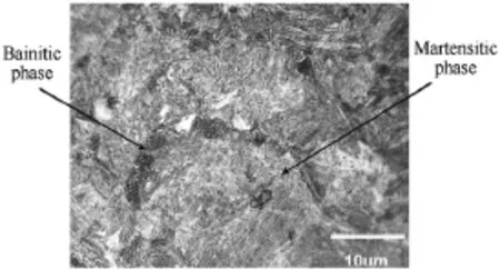
Fig.2.Experimental rolled homogeneous armour steel tempered Martensitic Bainitic microstructure,revealed with 5%Nital.
Table 2 shows the heat treatment conditions applied on the experimental steel,which consists of austenisation,quenching, and finally tempering,in accordance to the standards of manufacturing armour steels.The mechanical properties and hardness were increased to produce tougher and more durable steel. Here the parent steel was heated up to a critical transformation temperature of 1000°C and then water quenched to cause the soft initial material to transform to a harder and stronger structure.
Heating the material above the critical temperature causes carbon and the other elements to go into solid solution.The quenching process then freezes the microstructure,inducing stress.The steel plates were subsequently age tempered at 550°C for 60 min to transform the microstructure,achieve the appropriate hardness and eliminate the stresses.
Tempering is done to develop the required combination of hardness,strength and toughness or to relieve the brittleness of fully hardened steels.The combination of quenching and tempering is important to make tough parts.Tempering is the process of reheating the steel at a relatively low temperature leading to precipitation and spheroidization of the carbides present in the microstructure.The tempering temperature and times are generally controlled to produce the final properties required of the steel.The result is a component with the appro-priate combination of hardness,strength and toughness for the intended application.
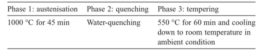
Table 2 The heat treatment conditions of the armour steel.
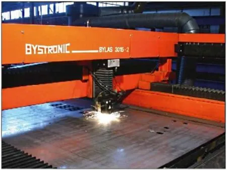
Fig.3.The Bystronic Bylas 3015 4.2 kW laser used to generate armour cut-edges.
The steel is quenched and tempered to sustain a tough surface for providing a high degree of ballistic protection.
2.2.Laser cut hole process parameters Laser cut-edges were performed using a Bystronic Bystar 4.2 kW laser,as shown in Fig.3.
Table 3 shows the test matrix that was used for generating cut-edge specimens,in which the traverse cutting speed was the dominant process parameter.A set of cuts were also performed using 100%pure oxygen in order to test the interaction between cutting gas and the silicone content in the steel.
Fig.4 shows the triangular lattice laser cutting configurations used during this study.The close proximity of each hole to the next hole results in 2800 holes per m2that were generated across the steel plate.
2.3.Characterisation
Surface micrographs of laser cut-edges were captured using a Leica optical light microscope.Microstructural characterisation and HAZ size measurements were analysed through observation of the specimens traverse to the cut-edge.Metallographic analysis of the near edge region microstructure was carried out by etching specimens using a 2%Nital reagent for 10 seconds.The microstructures were observed using a Reichert Polyvar optical microscope.In order to record and quantify cut-edge surface properties,a Taylor–Hobson form 2Talysurf was employed with scans being carried out across a two-dimensional surface area,providing an accurate representation of the cut-edge roughness and waviness data parameters together with the generation of axonometric profiles.The degree to which the cut-edge surfaces had hardened was measured as Hardness Vickers(Hv)microhardness,and measurements were taken using a Leco M-400-G2 hardness tester with a 500 g load.

Table 3 Laser cutting test matrix of parameters used to generate holes and cut-edges test pieces.
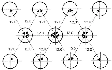
Fig.4.Dimensions of the triangular lattice hole configurations:10.0 mm diameter holes with spacing of 12.0 mm.
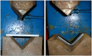
Fig.5.90°V-bend formability test with an armour test piece.
2.4.Formability testing
Sections of the laser cut samples were cut to expose the edge as shown in Fig.5.The bending radius is the curvature,which was measured by bending the cut-edge samples.These were placed into a v-shaped die and then formed using a knife edge punch to a 90°angle.These samples were formed at a stoke speed of 250 mm/s using a Dartec 250 kN hydraulic testing machine.Following the test-piece unloading,edges were analysed under a microscope for visible signs of fractures.
Induced cracking is based on both the hardness of the cutedge and also the roughness features formed on the surface during the cutting process.
3.Results and discussion
3.1.Topographical profiles of laser cut-edge surfaces
The surface roughness profiles of the laser cut-edges are shown in Fig.6.There was observed to be only slightly different formations of striations across the range of traverse cutting speeds.This is due to the fact that the formation of striations is harnessed during the cutting process by the pulsing operation, which limits and controls the beam interaction.
The surface roughness properties of the cut-edges examined are shown in Fig.7 where it was found that a traverse cutting speed of 1400 mm/min resulted in the smoothest cut-edge surface produced.Micrographs taken of the laser cut surfaces showed that there were more pronounced striations at a traverse cutting speed of 1000 mm/min.These features become less apparent as the traverse cutting speed was increased.However, these factors are important when considering the increase in surface area as striation properties are critical towards assessing the quality of the cut-edge surface.
These features are also important from the perspective of their microstructural properties,which consists of martensite. At a low cutting speed of 1000 mm/min,due to the conductionof heat,this allows the temperature to rise away from the cut zone and applies more heat to the cut front and the formation of a wide isotherm.

Fig.6.Surface axonometric profiles of laser cut-edges generated at cutting speeds of(a)1000 mm/min(b)1200 mm/min and(c)1400 mm/min.

Fig.7.Surface roughness parameters of laser cut-edges showing the Ra(arithmetic mean of departures from the mean line),Rp(maximum height of profile above the mean line),and Rv(maximum depth of profile below the mean line) properties.
Therefore,these results indicate that using a traverse cutting speed of 1400 mm/min will result in a surface which is optimum in terms of the formation of the most favourable surface roughness features.The microstructure around the zone of a cut-edge striation is shown in Fig.8,which consisted of martensite immediately close to the cut-edge,which was followed by the formation of some retained austenitic material, suggesting that the internal portion of the material would have cooled slower than the more critical surface.
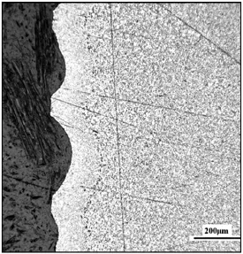
Fig.8.Cut through of the martensitic microstructure following the profile of a laser cut-edge striation.
Furthermore,Fig.9 shows the striation patterns formed at the top and bottom regions of the cut-edges.There was a noted decrease in the definition of the striations towards the bottom of the cut-edges across the full range of traverse cutting speeds. This is as a result of the divergent beam which becomes less intense and with a larger diameter.In the region at the bottom of the cut-edge the cutting gas also becomes responsible for the cutting and generating the kerf[21].
3.2.Laser heat-affected zone properties
The HAZ thickness of a laser cut-edge is an important component in determining the cutting.As the traverse cutting speed is increased,less of the laser power is absorbed into the material during the cutting process.The energy is instead used to cut through the steel.The transverse profiles of the HAZ are shown in Fig.10,in which it was observed that at the lowest cutting speed of 1000 mm/min,the HAZ was widest.
These results are quantified in Fig.11,in which the HAZ was observed to become thicker towards the bottom of the cut-edge across the full range of traverse cutting speeds.
At the traverse cutting speed of 1000 mm/min the HAZ size was 0.05 mm wider in comparison with the cutting speed of 1200 mm/min.Between cutting speeds of 1200 mm/min and 1400 mm/min there was again a 0.05 mm reduced HAZ thickness.It was measured that the perpendicularity of laser cutedges did change as the traverse cutting speed was increased; these were measured as
1000 mm/min=1.8°
1200 mm/min=2.3°
1400 mm/min=5.8°
The slight angularity of the cut-edges produced as the traverse cutting speed was increased.As a result there are two independent factors that occur as the cutting speed is increased. There is a decrease in HAZ size and an increase in angularity of the cut-edge.Although this is less pronounced due to the use of pulsed laser cutting,it is important due to the fact that there is an increase in surface angle and subsequent surface area.This is critical towards the ballistic properties of the steel.
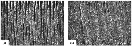
Fig.9.The pattern of striations formed at(a)the top,and(b)the bottom of a cut-edge at a cutting speed of 1000 mm/min.

Fig.10.Traverse profiles of the heat-affected zones generated at traverse cutting speeds of(a)1000 mm/min(b)1200 mm/min and(c)1400 mm/min.
3.3.Laser cut-edge hole and surface characterisation
Due to its highly focused properties and edge quality,laser cutting becomes the dominant procedure to perforate ultra hard armour products.Laser cutting was performed upon the steel in its post-annealed 725 Hv hardness condition.Fig.12 shows the quality of the cut holes produced at each set of cutting process parameters.The formation of a 10 mm laser cut hole provides an indication of cut-edge quality together with a suggestion of the quantity of dross generated during the process of cutting precise curvatures.These holes are later sectioned and bent to an angle of 45°to determine the formability limits of laser cut-edges.

Fig.11.Heat-affected zone measured thickness formed transverse to the laser cut-edges.
Laser through cuts are difficult to generate in the armour steel product due to the narrower spectrum of cutting process parameters as a result of the increased thickness of the material and the steel chemistry properties.
Fig.12 shows the holes produced when using the matrix of cutting process parameters.It can be clearly seen that using a lower transverse cutting speed resulted in an increase in dross being deposited.Holes generated were also of lower quality, becoming slightly distorted at the location where the laser beam joins to form the final hole geometry.
It was difficult to generate high quality laser cut-edges,as demonstrated by Fig.13(a).This was due to the fact that the steel product has 1.4%silicon as part of its chemistry which alters the viscosity of the laminar flow of liquid material as it reacts with the oxygen cutting gas during the laser cutting process.As a result,a mixture of 60%nitrogen and 40%oxygen cutting gas was used to produce high quality cut-edge surfaces at the most optimum speed,as shown in Fig.13(b).The increased concentration of Nitrogen was compensated by increasing the cutting gas pressure.
As the traverse cutting speed was increased it was observed that the formation of striations at the bottom of the cut-edges became less pronounced,as shown in Fig.14.The striations became finer and further apart at the top of the cut-edge as the traverse cutting speed was increased because the pulsing frequency remained the same as the traverse cutting speed was increased.There were some irregular surface disruptions noticed on the cut surfaces.These are caused by an increased molten flow of steel.This happens as the number of holes cutincreases,resulting in the workpiece heating up.As a result there is increased surface melting.
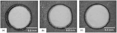
Fig.12.Underside regions of 10.0 mm laser cut-edge diameter holes generated using(a)1000 mm/min(b)1200 mm/min and(c)1400 mm/min cutting speeds, before removal of dross deposits.

Fig.13.Micrographs of holes generated using(a)100%pure oxygen at 3.5 kW and 1000 mm/min and(b)40%oxygen,60%nitrogen at 3.5 kW and 1000 mm/min.
The laser beam diameter and focal point on the steel workpiece is important to both the kerf width,hardness of the HAZ and the cut-edge surface roughness properties.A pulsing frequency on 65 Hz was used during the cutting process in order to in order to minimize the thermal distortion and reduce metallurgical deformations.
Fig.15 shows the processes,which occur during the laser cutting operation in order to generate a hole.The first stage is the piercing mode,which involves the laser being momentarily switched to a high power piercing state 3.8 kW.This produces a hole in the workpiece before being switched back to the preset cutting speed and power parameters.During this process the cutting gas continues to flow at the same pressure.The laser hole piercing operation was carried out away from the cut-edge so that the edge would remain undamaged by splash formed during the piercing phase of the laser cutting process.
3.4.Laser cut-edge hardness
The transverse hardness profile of a laser cut-edge generated at different traverse cutting speeds is shown in Fig.16.When comparing the hardness properties of the laser cut-edges it was observed that there is a significant increase in the cut-edge hardness.It was observed that there is a gradual increase in the hardness through the thickness of the cut-edge.This is because the laser bed on which the steel is mounted acts as a heat sink and subsequently quenches the steel.Faster cutting rates result in an increase in hardness.Using cutting speeds of 1000 mm/ min results in maximum hardness,peaking to 1158 Hv;the hardness increases to 1358 Hvat a traverse cutting speed of 1400 mm/min.
The profile at a traverse cutting speed of 1400 mm/min was observed to increase hardness by an average of 633 Hv compared with a cutting speed of 1000 mm/min in which the hardness increased by 433 Hv.
These results suggest that there is an interrelationship between the HAZ thickness and the surface hardness,in that although there was a narrower HAZ at 1400 mm/min,the cutedge surface was harder.The reason why the cut-edge hardness increases by so much is significantly due to the cutting gas properties.The Nitrogen content of 60%results in a quick cooling cycle.Subsequently there is an alteration in the metallurgical properties of the steel.This results in the formation ofmartensitic phases in the area close to the cut-edge.The hardness properties of the steel in this case are not necessarily a negative attribute.

Fig.14.Striations formed on laser cut-edge surfaces at each traverse cutting speed.Micrographs of laser cut-edge surfaces at traverse cutting speeds of(a) 1000 mm/min(b)1200 mm/min and(c)1400 mm/min.

Fig.15.The operations performed during the laser cutting process(a)Piercing mode,(b)switch to pre-set process settings,and(c)continuous cutting of the hole.
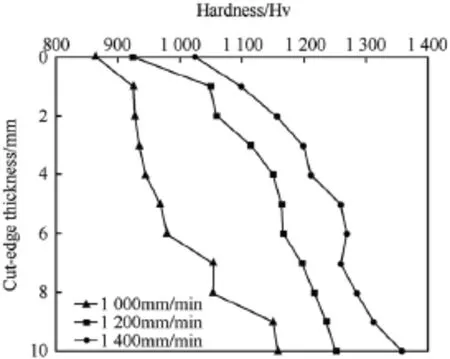
Fig.16.Transverse surface hardness profiles of laser cut-edges produced using the different process parameters.
3.5.Laser cut-edge microstructural properties
The microstructure and hardness of the steel was also observed to increase from the top to the bottom of the cut-edge. This is as a result of the interaction between the laser beam,the cutting gas properties and quenching from the laser bed.During this study the laser beam focuses on the surface of the steel, with the beam diverging throughout the workpiece thickness. As a result the cutting gas properties become very important. Here the pressure of the cutting gas and its properties pushes the molten steel through the kerf.Much of the heat is subsequently removed in the formation of the liquid metal.Some of this cooler material is deposited in the form of dross which becomes formed on the underside of the cut-edge.
As seen it has been seen,every step in the formation of the armour steel alloy,from casting and heat treatment,to rolling and annealing,contributes to the microstructure properties of the final product.Laser cutting also has an effect on altering the metallurgical microstructure of the steel.This is important due to the large number of holes that are cut within the workpiece. During the cutting process the workpiece heats up as a result of thermal absorption of the laser energy.The steel as a result starts off cool and increases in temperature as each subsequent hole is cut.
As the traverse cutting speed was increased to 1200 mm/min it was observed that there was a greater quantity of martensite in the region closest to the cut-edge surface as shown in Fig.17. At a 200 μm distance from the cut-edge there was still a component of martensite intermixed with wider regions of Bainitic phase found.
These results indicate that as the traverse cutting speed is increased,there is the susceptibility for the formation of a greater quantity of martensitic material and it is this factor that results in the increase of the surface hardness.These observations also align to the HAZ and hardness measurements of the cut-edge and indicate that precisely controlling the traverse cutting speed can also influence the intrinsic mechanical properties of the cut-edge surface region.

Fig.17.Micrograph of the microstructure in the HAZ regions generated at a traverse speed of 1200 mm/min.
A significant proportion of heat is concentrated in the melted material and removed from the kerf via the pressurized shielding gas.It was concluded that the temperature distribution is localised in the thin cut-edge surface layer and the energy coupling at the workpiece surface is important in terms of determining the cut-edge quality.Using a lower traverse cutting speed,as was in the case when cutting at a speed of 1000 mm/ min results in the beam being absorbed by the workpiece material,can cause undesirable solid-state heating,melting and vaporisation of the workpiece material as well as further problems such as workpiece distortion.
3.6.Edge formability properties
During the process of 90°edge bending at a sudden impact speed of 250 mm/s there was significant region where cut-edge cracks were observed.This was when the bottom regions of the laser cut-edges were placed under the highest degree of tension during the bending process.
Laser cracks were more predominant at lower traverse cutting speeds and after extensive analysis it was revealed that the cut-edge hardness was less critical and it was in fact the surface properties of the striation features that resulted in the formation of cracks.Fig.18 shows the cracks formed when the bottom of laser cut-edges were put under tension.The cut-edges produced at a traverse cutting speed of 1400 mm/min were harder than those produced at 1000 mm/min,although there were more cracks formed at a traverse cutting speed of 1000 mm/min.
When comparing the data,it is logical to suggest that formability fractures produced during the bending operation initiated from deeper striations,and that this is more significant to cracking than the cut-edge hardness properties.As it is shown in Fig.18 at a traverse cutting speed of 1000 mm/min,this resulted in the formation of deep striations that as a result opened up to form cracks during the bending process.
Although it could not be positively determined,the microstructure of the bottom region of the workpiece may also suggest that this was the region of crack initiation,which was determined to initiate from a corner region where hard martensite was formed during the cutting process.
The regions close to the cut-edge were found to transform back to the parent Martensitic–Bainitic microstructure in a gradual process consisting of different microstructural regions as shown in Fig.13.
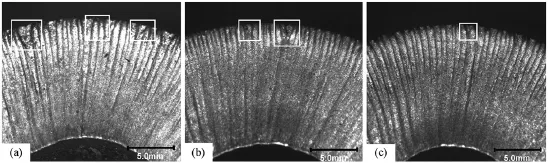
Fig.18.Cracks formed with the bottom of the laser cut-edge in tension at traverse cutting speeds of(a)1000 mm/min(b)1200 mm/min,and(c)1400 mm/min.
4.Conclusions
The formation of an Appliqué armour plate has been found to be suitable for manufacturing using laser cutting processes.The array of holes acts as a double-edged solution,in that they provide weight saving of 45%and,although it may seem like an atypical solution,introducing holes to vehicle armour provides a protective advantage.The perforated armour is a circular edge rather than a holeandwhenaprojectilehitsthisedge,itgetsdeflectedandturns froma sharp projectile into a bluntfragmentwhichmakesiteasier to stop by the vehicles existing armour superstructure.Furthermore,the perforated armour also absorbs energy from explosions across a greater surface area.These manufactured plates can be retrofitted to an armoured fighting vehicle to withstand munitions thatcanpenetratetheoriginalarmourofthevehicle.Anadvantage of appliqué armour is the possibility to tailor the vehicle’s protection level to a specific threat scenario.
Process parameters of laser cut-edges produced when using a traverse cutting speed of 1200 mm/min displayed the optimum intermediary properties.These parameters resulted in the generation of a surface with less stress rising features.This can result in a distribution of stress across the wider surface.It can,therefore,be concluded that the striation shape will significantly influence critical ballistic properties.
Provided that appropriate process parameters are used to generate laser cut edges,the hardness properties of the surface can be controlled.This is due to compressive residual stresses produced in the near edge region as a result of metallurgical transformations.This way the traverse cutting speed parameter can be adjusted to alter critical surface characteristics and microstructural properties in close proximity to the cut-edge.
Acknowledgment
The author wishes to thank the support of Swansea University during the pursuit of this research.
References
[1]Edwards MR,Mathewson A.The ballistic properties of tool steel as a potential improvised armour plate.Int J Impact Eng 1997;19(4):297–309.
[2]Demir T,Übeyli M,Yildirim RO.Investigation on the ballistic impact behaviour of various alloys against 7.62 mm armour piercing projectile. Mater Des 2008;29(10):2009–16.
[3]Gonçalves DP,de Melo FCL,Klein AN,Al-Qureshi HA.Analysis and investigation of ballistic impact on ceramic/metal composite armour.Int J Mach Tools Manuf 2004;44(2–3):307–16.
[4]Shokrieh MM,Javadpour GH.Penetration analysis of a projectile in ceramic composite armour.Compos Struct 2008;82(2):269–76.
[5]Karagoz S,Atapek SH,Yilmaz A.Microstructural and fractographical studiesonquenchedandtemperedarmoursteels.MaterTest 2010;52(5):316–22.
[6]Gama BA,Bogetti TA,Fink BK,Yu CJ,Claar D,Eifert HH,et al. Aluminium foam integral armour:a new dimension in armour design. Compos Struct 2001;52(3–4):381–95.
[7]Maweja K,Stumpf W.The design of advanced performance high strength low-carbon martensitic armour steels:part-1.Mechanical property considerations.Mater Sci Eng A Struct Mater 2008;485(1–2):140–53.
[8]Dikshit SN.Influence of hardness on perforation velocity in steel armour plates.Def Sci J 2000;50(1):95–9.
[9]Borvik T,Dey S,Clausen AH.Perforation resistance of five different high-strength steel plates subjected to small-arms projectiles.Int J Impact Eng 2009;36(7):948–64.
[10]Hu CJ,Lee PY,Chen JS.Ballistic performance and microstructure of modifiedrolledhomogeneousarmoursteel.JChinInstEng 2002;25(1):99–107.
[11]Sangoy L,Meunier Y,Pont G.Steels for ballistic protection.Israel J Technol 1988;24:319–26.
[12]Jena PK,Kumar KS,Krishna VR,Singh AK,Bhat TB.Studies on the role of microstructure on performance of a high-strength armour steel.Eng Fail Anal 2008;15:1088–96.
[13]Shipway PH,Wood SJ,Dent AH.The hardness and sliding wear behaviour of a bainitic steel.Wear 1997;203:196–205.
[14]Shah SM,Bahadur S,Verhoeven JD.Erosion behaviour of high silicon bainitic structures;Part II:high silicon steels.Wear 1986;113:279–99.
[15]Zhenming X,Qichuan J,Yuguang Z,Yanjun L,Zhenming H.A new type of wear resistant austenite bainite steel with granular carbides modified by boron and cerium rare earth.J Mater Sci Lett 1995;14:1410–11.
[16]Ping L,Bahadur S,Verhoeven JD.Friction and wear behaviour of high silicon bainitic structures in austempered cast iron and steel.Wear 1990;138:269–84.
[17]Meurling F,Melander A,Linder J,Larsson M,Trogen H.The influence of laser cutting on the fatigue properties of thin sheet steels.Swedish Institute for Metals Research Report IM-3691.1998.
[18]Hasçalık A,Ay M.CO2 laser cut quality of Inconel 718 nickel–based superalloy.Opt Laser Technol 2013;48:554–64.
[19]Eltawahni HA,Hagino M,Benyounis KY,Inoue T,Olabi AG.Effect of CO2 laser cutting process parameters on edge quality and operating cost of AISI316L.Opt Laser Technol 2012;44(4):1068–82.
[20]Schulz W,Becker D,Frankr J,Kemmerling R,Herziger G.Heat conduction losses in laser cutting of metals.J Phys D Appl Phys 1993;26:1357–63.
[21]Thomas DJ.The influence of the laser and plasma traverse cutting speed process parameter on the cut-edge characteristics and durability ofYellow Goods vehicle.J Manuf Process 2011;13:120–32.
[22]Chocron S,Anderson C Jr,Grosch D,Popelar C.Impact of the 7.62-mm APM2 projectile against the edge of a metallic target.Int J Impact Eng 2001;25:423–37.
[23]Radisavljevic I,Balos S,Nikacevic M,Sidjanin L.Optimization of geometrical characteristics of perforated plates.Mater Des 2013;49:81–9.
[24]Balos S,Radisavljevic I,Rajnovic D,Dramicanin M,Tabakovic S, Eric-Cekic O,et al.Geometry,mechanical and ballistic properties ofADI material perforated plates.Mater Des 2015;83:66–74.
Peer review under responsibility of China Ordnance Society.
.Tel.:+4401656737349.
E-mail address:D.J.Thomas@swansea.ac.uk(D.J.THOMAS).
5 June 2016;revised 27 June 2016;accepted 19 July 2016
杂志排行

Defence Technology的其它文章
- Theoretical analysis of the surface temperature regulation of an infrared false target subjected to periodical ambient conditions
- An inexpensive underwater mine countermeasures simulator with real-time 3D after action review
- Metallurgical analysis of a failed maraging steel shear screw used in the band separation system of a satellite launch vehicle
- Selective maintenance problem for series–parallel system under economic dependence
- An overview on importance,synthetic strategies and studies of 2,4,6,8,10,12-hexanitro-2,4,6,8,10,12-hexaazaisowurtzitane(HNIW)
- Misconceptions in global reactions and formula writing Stig R.JOHANSSON*