New design of a compact aero-robotic drilling end eff ector:An experimental analysis
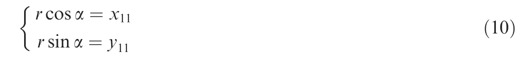
2016-11-24ShiZhenyunYunPeijingWngQishenChenDongdongWngTinmio
Shi Zhenyun,Yun Peijing,*,Wng Qishen,Chen Dongdong,Wng Tinmio
aSchool of Mechanical Engineering and Automation,Beihang University,Beijing 100083,China
bBeijing Institute of Aerospace Control Devices,Beijing 100854,China
New design of a compact aero-robotic drilling end eff ector:An experimental analysis
Shi Zhenyuna,Yuan Peijianga,*,Wang Qishenb,Chen Dongdonga,Wang Tianmiaoa
aSchool of Mechanical Engineering and Automation,Beihang University,Beijing 100083,China
bBeijing Institute of Aerospace Control Devices,Beijing 100854,China
This paper presents the development of a normal adjustment cell(NAC)in aero-robotic drilling to improve the quality of vertical drilling,by using an intelligent double-eccentric disk normal adjustment mechanism(2-EDNA),a spherical plain bearing and a floating compress module with sensors.After the surface normal vector is calculated based on the laser sensors’feedback,the 2-EDNA concept is conceived specifically to address the deviation of the spindle from the surface normal at the drilling point.Following the angle calculation,depending on the actual initial position,two precise eccentric disks(PEDs)with an identical eccentric radius are used to rotate with the appropriate angles using two high-resolution DC servomotors.The two PEDs will carry the spindle to coincide with the surface normal,keeping the vertex of the drill bit still to avoid repeated adjustment and position compensation.A series of experiments was conducted on an aeronautical drilling robot plat form with a precise NAC.The effect of normal adjustment on bore diameter,drilling force,burr size,drilling heat,and tool wear was analyzed.The results validate that using the NAC in robotic drilling results in greatly improved vertical drilling quality and is attainable in terms of intelligence and accuracy.
1.Introduction
A normal adjustment cell is highly desirable in robotic drilling if vertical drilling quality is to be improved.Drilling in a deflective direction from the surface normal will result in lower drilling quality in terms of verticality and bore diameter,which could be catastrophic for the safety of aircraft.In recent years,many aircraft crashes have been attributed to fatigue cracks at the connecting holes of aircraft structures.1Propagation of the cracks is directly related to the normal stresses perpendicular to the surface of the aircraft,2so the quality of vertical drilling largely determines the safety and fatigue life of the aircraft.3,4To enhance aircraft structural strength,improvefatigue life,and reduce the weight of the aircraft,many difficult-to-cut metals,such as titanium alloys,5,6super alloys,7and composite structures,8have been adopted in the design of the modern aircraft,which makes it not only difficult to drill with stability,but difficult to repair.In particular,carbon fiber rein forced plastics(CFRP)are susceptive to a non-uniform drilling force when subjected to drilling along a deflective direction9;this can result in interface delamination,which is considered to be among the major damage problems caused by drilling.10,11The traditional method to guide the drilling direction along the surface normal is to use a drilling template,12which cannot satisfy the requirements of accurate and automated robotic drilling.For these reasons,a normal adjustment cell(NAC) for use in robotic drilling is a desired and challenging technology in automated aircraft assembly.
With the development of robotic technology,the use of robotic drilling in aircraft digital assembly has been of interest.A robotic drilling system based on an industrial robot has been widely used in drilling for different aircraft parts.13–15Moreover,the crawling drilling robots,such as MTorres and the Fatronik system,are now available16–19and have become a hotspot of research,although the crawling designs have their own limitations and are not suited for all kinds of conditions.These designs require stiffness of the structure of the aircraft parts.To improve the drilling verticality,Electro Impact,in cooperation with Boeing,has developed theflex-track drilling robot.20This system can attach and con form to a curved surface,even with varying curvatures,to accurately drill and is considered to be a key technology.The system has gained wider attention because of a special probe mechanism and a variety of sensors that are used to create this functionality.21,22
To apply the verticality detection result into production,adjustment mechanism design of the surface normal is also another core technical feature.With regard to normal adjustment,there are mainly two approaches.23One is that each normal attitude of both the spindle and the work piece is adjusted,such as through the three-point bracket regulation algorithm.24This makes it difficult to meet the processing site’s demand of drilling for a large work piece and real-time attitude adjustment.The other approach is that only the spindle realizes attitude adjustment,and in this case thefour or five axes of the drilling apparatus are used to realizefine vertical adjustment of the spindle,25keeping the work piece still.However,this is not only expensive,but large in size,and the verticality of the spindle is adjusted by joint motions,26,27which are small in terms of volume but long in the adjustment path.Most current commercial end effector systems are designed based on these two approaches:as shown in Table 1,traditional mechanical structures require larger volumes or longer adjustment paths,and the unit weight for all commercial verticaldrilling end effectors is more than 100 kg.For all these reasons,the double eccentric disk normal-adjustment mechanism(2-EDNA)design was conceived to easily and accurately adjust the verticality of the spindle under the premise of keeping the vertex of the drill bit still and avoiding repeated adjustment,and thefeatures of the mechanism also ensure the compact of the volume.
Basically,to achieve high drilling quality,automatic detection and adjustment of the surface normal are hot topics in all types of drilling robots,and in this paper we provide a newly designed NAC for robotic drilling that can adjust the spindle to coincide with the surface normal,keeping the vertex of the drill bit still to avoid repeated adjustment and position compensation.In addition,a floating compress module is setto supply the surface normal vector detection.The rest of this paper is organized as follows:Section 2 introduces the working procedure of the major function modules in robotic drilling processing for aerostructures.Section 3 describes the innovative mechanism design of a drilling end effector,especially the NAC part.In Section 4,the adjustment algorithm applied by 2-EDNA is presented,followed by the experiment and results analysis in Section 5.Section 6 concludes the work.
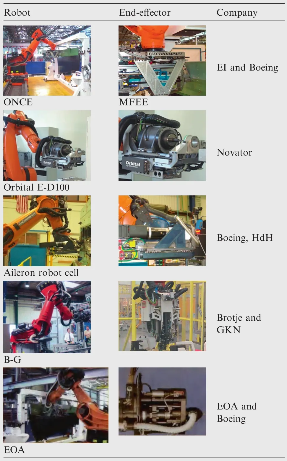
Table 1 Part of the commercial end effector systems.
2.System overview
Based on there quirements of aero-roboticdrilling for aerostructures,we present a newly designed end effector with an intelligent normal adjustment cell(NAC)that relies on a double-eccentric disk normal adjustment mechanism(2-EDNA)to accomplish surface normal adjustment,using a surface normal measuring module to achieve the rotation angle of the NAC.The whole process of normal adjustment can then be carried out automatically.Drilling efficiency is improved and drilling accuracy is ensured.The initial version of the NAC drilling system was constructed in 2013,28,29and its 2-EDNA design was the first of its kind.As with the earlier version,our updated system must still be optimized to solve several weaknesses(e.g.,the 2-EDNAs transmitting gear does not have close-looping control and gear clearance makes the adjustment angle less reliable;the normal measuring unit for the surface exhibits limited measurable curvature,a fact that makes it unsuitable under large-curvature conditions;and the connection between the spindle axis and spherical pair must be optimized to better suit live applications and provide stability).To solve all the weaknesses in the initial version some mechanisms were redesigned to provide better stability and wider applicability,and several additional sensors were added to provide greater accuracy.To improve the adjustment angle accuracy of the NAC system,two absolute encoders were fitted to the 2-EDNAs,and they interfaced with the tilt sensor to verify the spindle’s actual posture;a spherical plain bearing sits in the lower part of the NAC to constrain its motion,and multiple spherical supporters made of super wear-resistant materials have also been added.To achieve a reliable surface-normal vector on high-curvature surfaces,a floating-compress module has been added to the bottom of the end effector.After being fitted with the surface surrounding the drill point,three points of the compress module’s upper surface were measured using three laser-range sensors,and the testing values were translated into the surface-normal vector.Additionally,other sensors,including a linear encoder and linear–displacement transducer(LDT),were added to ensurefeeding distance and countersinking accuracy.
Be fore the drilling robot starts,the drilling point is marked.Once the system starts,the marker will be captured by a visual positioning system and its center will be positioned.According to the obtained coordinates,the end effector is driven to move so that the axis of the spindle passes through the drilling point.The surface normal vector of the drilling point is measured using three laser range sensors,as soon as the end effector stops moving.All these coordinates arefed back to the controller to calculate the unit’s surface normal vector at the drilling point(Fig.1).Using the unit’s surface normal vector,the rotation angles of the large and small precise eccentric disks(PEDs)can be calculated.Then the controller will issue instructions to drive two high-resolution DC servomotors(DC-SM),which can carry two PEDs,to rotate with respective angles in the form of a gear drive.Owing to the eccentricity of the two PEDs and the support from the ball joint,the spindle inset of the small PED is carried to anywhere within the adjustment area of ±5°.The motion of the two PEDs is closed-loop controlled with encoder feedback.Ultimately,the axis of the spindle coincides with the surface normal at the drilling point.
The deviation between the surface normal and the axis of the spindle was detected by the three laser sensors.If the deviation is less than 0.4°,the drilling begins;otherwise,the spindle is adjusted by the NAC to drill in the surface normal direction.The intelligent NAC is conducive to robotic drilling.
3.Innovative design of drilling end effector
To accurately adjust the spindle normally with a compact mechanism the NAC is designed to receive the servo circular-motion mechanism with two PEDs and a spherical plain bearing,as shown in Fig.2.With these constraints,the end of the spindle can arrive at every point on a certain area of spherical surface such that Ospis the center and D the diameter based on posture adjustments,which finely adjust the two rotating degrees of freedom(DOFs);Rxand Ry,in the axial direction.O0is the center of the large PED,point O1the center of the small PED,and point O2the normal adjustment position.θ is the adjustment angle.Meanwhile,the NAC provides the drill its axial feed.
The end effector is mounted on an industrial robot,KR210R2700 extra,while the NAC is placed inside theframe.All components,including the 2-EDNA,spindle motor,drill clamp,and drill bit are situated on a spherical surface of the spherical plain thrust bearing at the lower portion of the end effector.The center of the spherical plain thrust bearing coincides with vertex Ospof the drill bit to keep point Ospstill when adjusting,avoiding repeated measurement and adjustment,and there fore,no position compensation.
The drilling tail shaft at the rear end of the spindle,which is co-axial with the axis of the drill bit,passes through a linear ball bearing.There are two PEDs with an identical eccentric radius r.The small one,in which the self-lubricating spherical plain bearing is situated,is embedded in the large one and can rotatefreely.When these two PEDs rotate to an appropriate angle along a certain direction(clockwise or anticlockwise)from the initial position,constant angle adjustment of the spindle can be accomplished,keeping the vertex of the drill bit still.
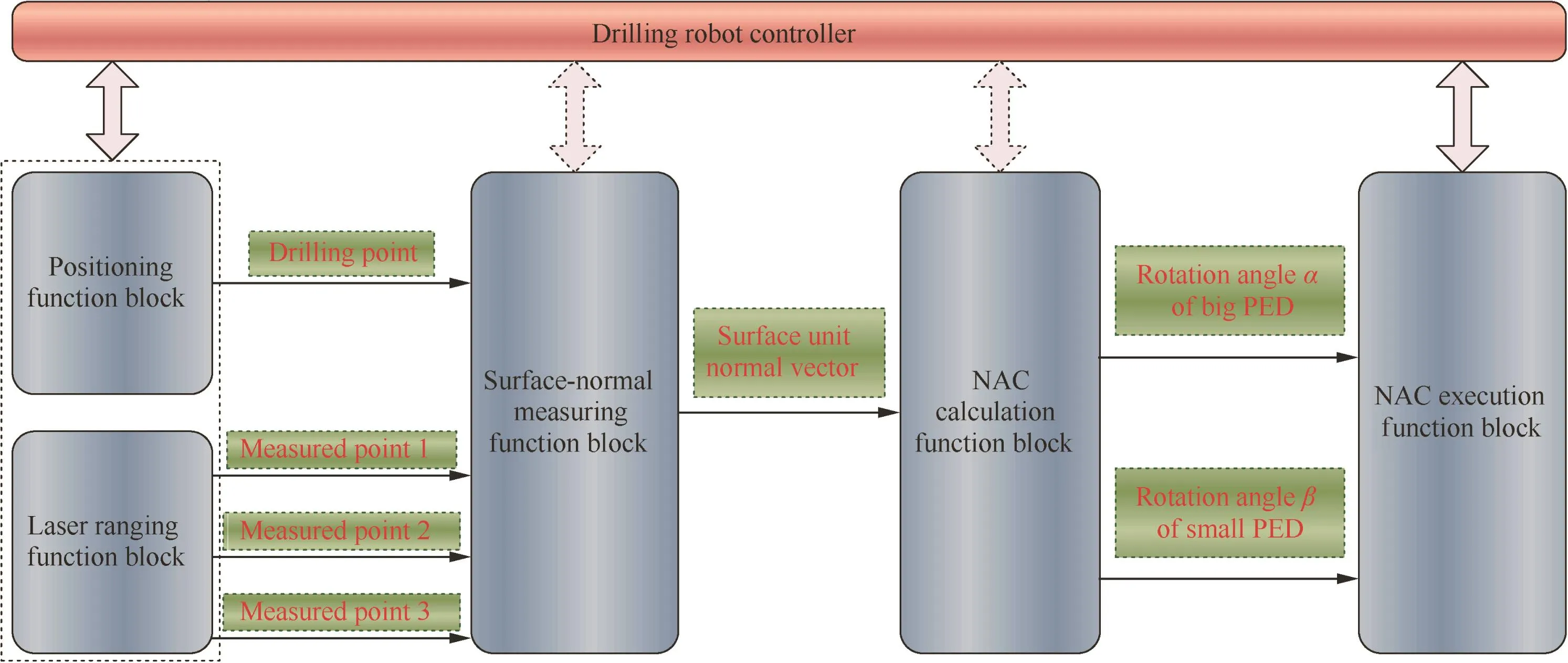
Fig.1 Working procedure of surface normal measurement and adjustment.
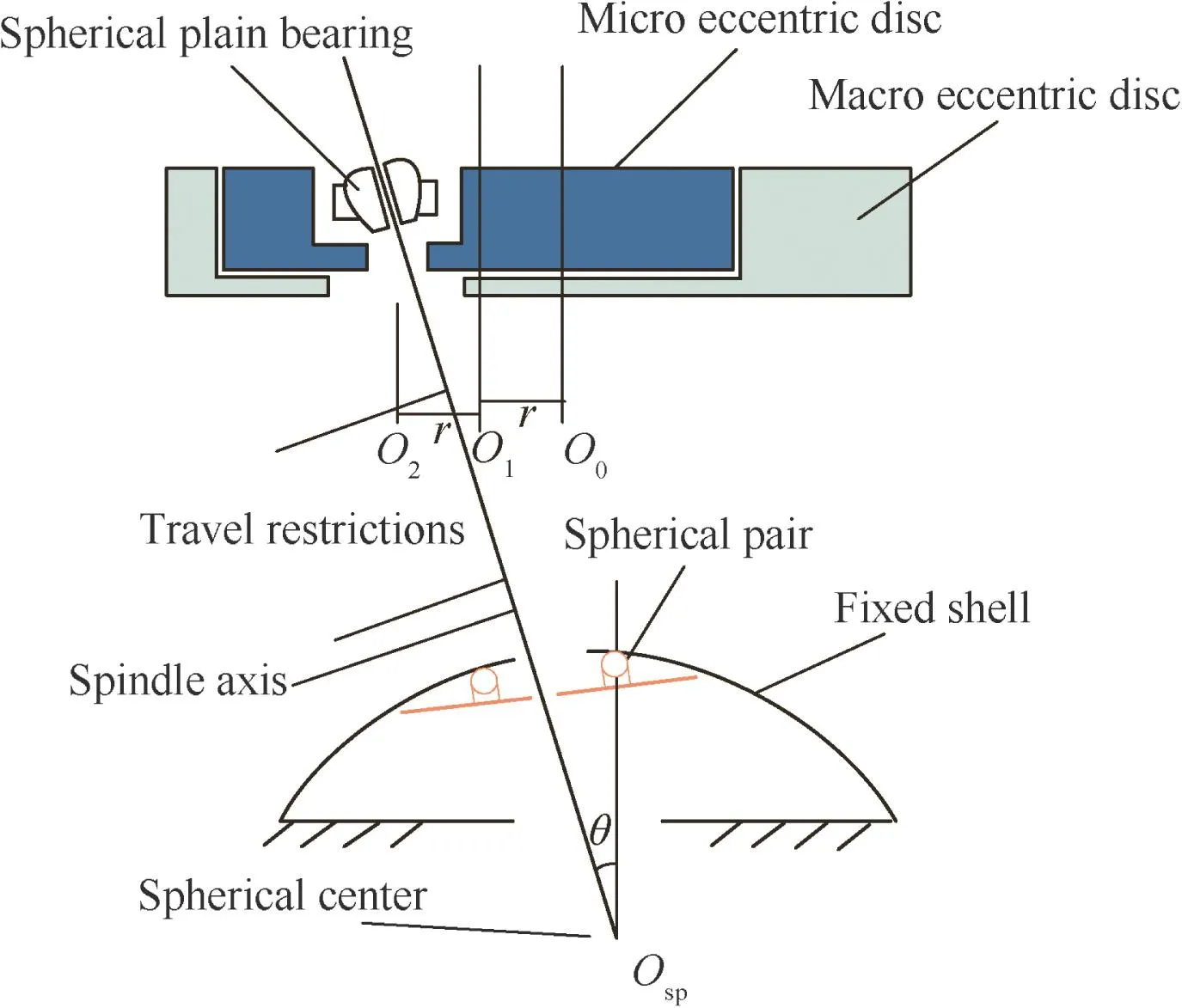
Fig.2 Schematic diagram of NAC system.
To keep the point Ospcoinciding with the drilling position as in the theoretical presentation,it is required to achieve the actual distance between the top of the drilling bit and the work piece surface.Also,during the compress processing,the cylinder extending distance varies with different work piece de formations.To accurately control the feeding distance of the spindle,an LDT is added to the compress module to calculate the pressing distance,and a linear encoder is used to test the real feeding distance of the feed motor(Fig.3).In addition to the feedback systems described above,a self-designed testing unit is used to measure the distance between the drill clamp bottoms and the top of the drilling bit after each reassembly of the drilling bit.Four motors are setting inside the end effector,including two adjustment motors,one spindle motor and onefeed motor.The parameters of the motors are listed in the Table 2.
4.Adjustment algorithm of NAC
As Fig.4 shows,the distance between the drill bit’s vertex and adjustment plane π for the two PEDs is expressed as D,which is 570 mm,based on motor selection,spindle design,feed distance requirements and several other design details.Based on the surface normal vector at the drilling point calculated by feedback from the three lasers,the normal adjustment position O2at plane π can be obtained.L is the distance between the drilling point P and the point O2.
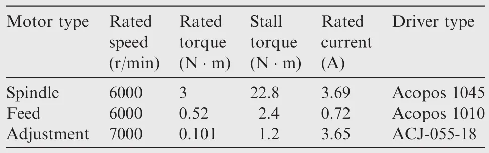
Table 2 Data for motors parameter.

Fig.4 Schematic diagram of normal adjustment.
To analyze the relationship between the normal adjustment angle and the rotation angle of the two PEDs,we simplified the normal adjustment schematic diagram into the two PEDs model(see Fig.5).

Fig.5 Schematic of two PEDs’model.
The two PEDs have an identical eccentric radius r(Fig.5).The small PED is mounted within the eccentric circle of the large PED,around whose center the small PED can rotate freely.The drilling tail shaft of the spindle passes through the eccentric circle of the small PED.When adjusting,the spindle will be carried to normal adjustment position O2.
In the initial state,point O2coincides with center O0of the large PED,and point O1is on the x axis.When points O0,O1,and O2are collinear,the maximum adjustment distance is reached,namely,radius Rmax=2r.In the 2-EDNA cell,distance D is 570 mm,so the maximum adjustment angle φ can be obtained as
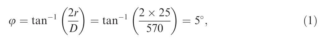
where r=25 mm.Hence,the maximum adjustment area of 2-EDNA is ±5°.The two disks’external diameters are 200 mm and 94 mm,respectively,whose measurements are based on mechanism-space requirements and the NAC motor’s external dimensions.
To know how many angles the two PEDs rotate,one must determine angles α and β.Without loss of generality,suppose that point O2in Fig.5 is the normal adjustment position.The coordinate of point O2can then be written as

After the angles α and β are obtained,the two PEDs are driven by the DC-SM to achieve the respective target angles,and the spindle can be adjusted to drill along the surface normal direction toward the drilling point.However,to increase the efficiency,it is necessary to apply the attitude adjustment continuously and without return to the initial position,and the algorithm of attitude adjustment should take the current posture as the zero position.
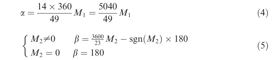
Be fore the adjustment,the on-time posture of the PEDs is achieved by the calculation based on the two absolute encoders.Each of the PEDs has three gears and the gear numbers are Z1=28,Z2=32,Z3=98 for the big PED,and Z′1=20,Z′=26,=46 for the small PED.The angle differences of the two PEDs from the zero position to the on-time position are M1and M2,based on the gear relationship,the angles α and β can be achieved
Putting α and β obtained from Eqs.(4)and(5)into Eq.(2),the on-time coordinate point position can be achieved and treated as the original position.Both eccentric disks have two directions,clockwise and counterclockwise.For the same target position,the PEDs always have two paths to arrive at the posture.As shown in Fig.6,O2is the current position of the spherical plain bearing,and O′2is the target position.For O′2,both path 1 and path 2 shown by the solid line and dotted line,can reach the target.For the same reason,the mathematical equation of the corresponding rotation angle also has multiple solutions.In our case,determining the optimal rotation angles of the two PEDs for higher efficiency is the target.
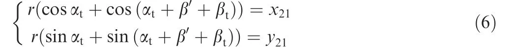
Based on the simplified model of Fig.6,we try to establish the plane coordinate system of the double eccentric disks in the current posture to achieve the optimal rotation angles αtand βtof the two PEDs.As shown in Fig.7,the x1Oy1coordinate system represents the state of the original position of the PEDs,the x2Oy2coordinate system represents the state of the target position of the PEDs,αtand βtdescribe the relative state of the OO1–O1O2compared with the state of the OO′1–O′1O′2and β′is the rotation angle from x1to x2.
The position of O2(x21,y21)can be described as follows:
By solving the inverse trigonometric function,the solution of αtcan be achieved as
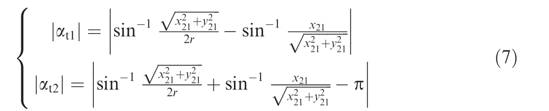
From the function,we can always get two absolute values of the solution;to improve the efficiency,the lower value of αtis the preferred solution,in which αt=min(|αt1|,|αt2|).After that,we used a simple method to solve the value of βt.As shown in Fig.7,the rotation angle βtis the intersection angle between two vectors O1O2and x2axis,which can be achieved by the standard equation
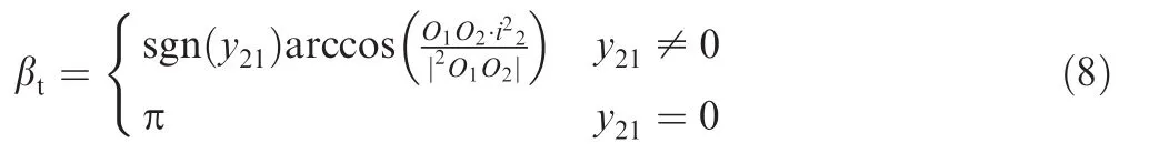

Fig.6 Multiple solutions to one target posture.

Fig.7 Current coordinate system of double eccentric disks.
in which2O1O2represents the O1O2vector in the x2Oy2coordinate system,and i2the unit vector along the 2 axis.The2O1O2can be obtained by:in which R12represents the rotation trans formation matrix from the x1Oy1coordinate system to the x2Oy2coordinate system.And according to Fig.7,the coordinates of O1in the x1Oy1coordinate system are
Substituting the two αtvalues obtained from Eq.(7)into Eqs.(8)–(10)can achieve two corresponding βtvalues.Two group solutions are further substituted into Eq.(6)to verify the optimized solution by comparing the consistency of the result and the target coordinate.αtand βtrepresent the optimal rotation angles of the big PED and small PED separately.
5.Experimental results and analysis
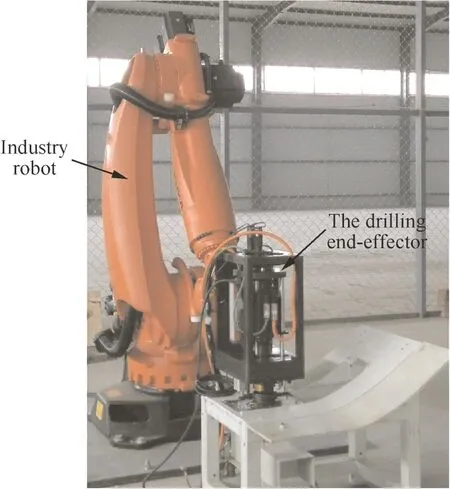
Fig.8 Flex-track drilling robot plat form.
A drilling experiment,which takes the NAC of the spindle into account,was conducted on an industrial drilling robot plat form(see Fig.8).The experiment was conducted by drilling aircraft skin made of different materials,such as aluminum alloy(Al),CFRP,and titanium alloy(Ti)using the NAC.After the experiment,the effect of the NAC on drilling quality,drilling force,thermal damage and drilling tools was analyzed separately.
5.1.Drilling experiment using NAC
High-quality and automated drilling is the ultimate purpose of the NAC.Al,Ti and CFRP were selected as the drilling materials to be drilled by the aero-drilling robot using the NAC.Based on the three laser’s distance feedback results(d1,d2,d3),the surface normal vector can be calculated,and three sets of normal adjustment data for Al,Ti,and CFRP were determined,as listed in Table 3.The controller then issued commands to drive two DC-SMs,which rotated the two PEDs to their respective angles.As a result,the spindle realizes three-dimensional space motion,which is a coning motion.Ultimately,the axis of the spindle coincides with the surface normal,keeping the vertex of the drill bit still and avoiding repeated adjustments.
Depending on different materials,different drilling parameters need to be set as follows and then the robot accomplishes drilling.
(1)Drilling for aluminumA combined carbide drill and countersink tool was used to drill the Al,whose thickness is 6 mm.The diameter of the drilling part is 6 mm,the taper angle of the countersinking part is 100°and the countersinking depth is 2 mm.
(2)Drilling for CFRPThe thickness of the CFRP is 8 mm and the ultimate diameter is 12 mm.We present two processes—drilling and reaming.The spindle speed was set at 6000 r/min in drilling,but 1000 r/min for reaming.For both drilling and reaming,the feed speed is 25 mm/r.
(3)Drilling for titanium Similar to drilling for CFRP,the thickness of the Ti is 8 mm and the ultimate diameteris12 mm.Wealso present the same processes as those for CFRP—drilling and reaming.For drilling,the spindle speed was set as 800 r/min and the feed speed is 10 mm/min.When reaming,the spindle speed is 1000 r/min and thefeed speed is 25 mm/min.
The drilling results are shown in Fig.9.All holes were within ‘H8”,which demonstrates that the NAC is feasible and accurate.The differences between drilling with or without NAC were compared in thefollowing text,and the bore diameter tolerance,the drilling force,the drilling heat,the burr height and the drill bit service life were chosen as the main features.
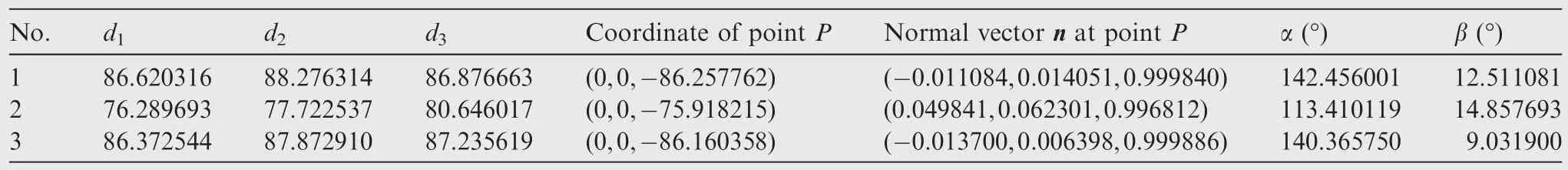
Table 3 Data for normal adjustment.

Fig.9 Robot drilling effect for Al,CFRP and Ti using NAC.
5.2.Effect of normal adjustment on bore diameter
The deviation of the spindle can result in an elliptical hole,which will affect the aircraft assembly.Fig.10 shows the diameters of the holes drilled by robotic drilling with the NAC and without the NAC,and for ease of comparison,Ti and CFRP are chosen for the same bore diameter.By using the NAC,the maximal bore diameter is 12.014 mm and the minimal value is 12.008 mm for CFRP,concluding that the tolerance is 0.006 mm; for Ti,the maximal bore diameter is 12.019 mm and the minimal value is 12.012 mm,concluding that the tolerance is 0.007 mm.All of these were applied within ‘Ø12H8”and with improved circularity of the drilling.Without the NAC,the tolerance was increased to 0.042 mm for CFRP and the tolerance is 0.028 mm for Ti,which is not acceptable.The Al presents a similar situation,without the NAC the tolerance was increased from 0.008 mm to 0.024 mm.
5.3.Effect of normal adjustment on cutting force
The deviation of the spindle could extremely affect the drilling force,which has a significant influence on drilling quality factors,such as flank wear,surface roughness,bore diameter and the height of burr.In the test of the 6 mm thick Al for 6 mm drilling diameter(Fig.11(a)),without the normal adjustment,the maximal axial force Fzduring the ordinary drilling process achieves 39 N.However,due to the deviation of the axis of the drill bit,the radial force Fxand the tangential force Fyalso increase,which inevitably leads to bending de formation of the drill bit and an influence on the drilled bore diameter.
As shown in Fig.11(b),the robotic drilling using the NAC reduces the radial force Fxand the tangential force Fyto 8 N and 10 N,respectively.And the maximal axial force Fzis reduced to 32 N.In addition,within the approaching process of stage ‘ab’and the retracting process of stage ‘bc’,shown in Fig.11(b),the force values become smoother.All these prove the superiority of the normal adjustment.Further experiments will be applied to more materials with different thicknesses.
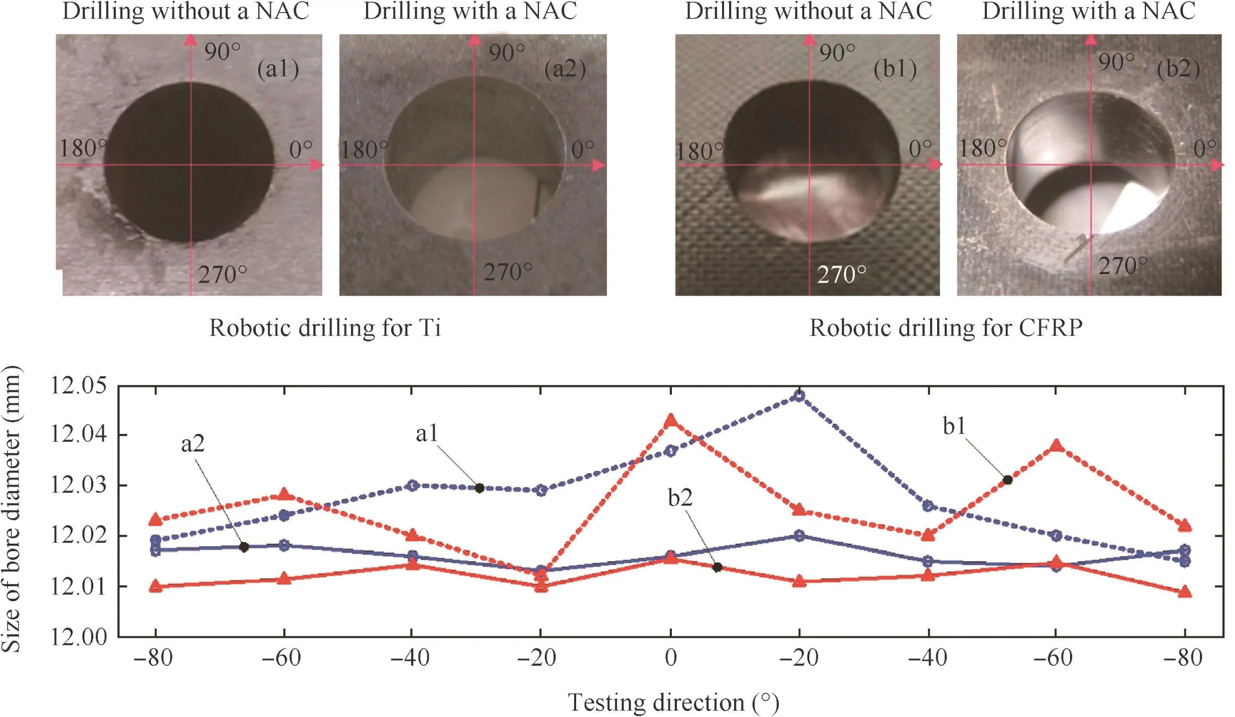
Fig.10 Bore diameter analysis of CFRP and Ti drilled after attitude adjustment using a NAC.

Fig.11 Comparison of drilling force.
5.4.Effect of normal adjustment on drilling heat
We chose the Al with 6 mm thickness to analyze the drilling heat effect of the hole wall.Fig.12 shows the drilling heat images for ordinary drilling and robotic drilling with attitude adjustment.Both Fig.12(a)and Fig.12(b)show that the images amplified 100 times(left)and 500 times(right).From the images in Fig.12(a),we see that there is a cycle of black trace burns on the hole wall in the ordinary drilling process without the NAC,which is because there is much drilling heat that leads to severe surface thermal damage of the holes.However,there is little drilling heat in robotic drilling with the NAC.So,robotic drilling with the NAC can decrease the drilling temperature and improve the surface quality of the holes.In addition,the decrease in drilling heat can significantly improve the stress distribution on the surface of the holes,helping to avoid tiny cracks and increase thefatigue strength of the holes.More images will be taken to prove this conclusion on more materials.
5.5.Effect of normal adjustment on height of burr
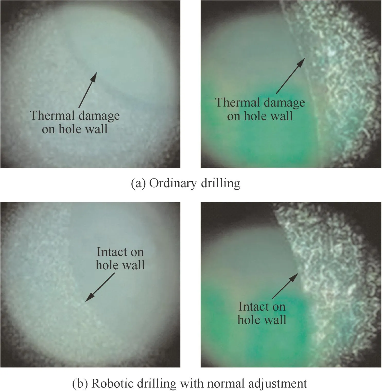
Fig.12 Drilling heat images under microscope.
While drilling,the deviation of the spindle will cause uncertain- force values at the hole’s exit,generating an uneven burr height around the exit.In fatigue testing,the burr is always one source of cracks and a shorter burr can improve thefatigue life and achieve better connection quality.The illustrations of the burr around the exit with and without NAC adjustment are shown in Fig.13(a),in the test of the 6 mm thick Al with 6 mm drilling diameter.As shown in Fig.13(b),the burr at the half-side pressed greatly was high(round dot)and the highest burr is 274 μm.However,at the halfside pressed little,the shortest burr is 105 μm.If the spindle is adjusted through the NAC be fore drilling,the height of the burr will be remarkably decreased,as the diamond markers,and the average height of the burr is only 103 μm,which also proves the essentiality of the normal adjustment.The same test in further experiments will be applied to more materials with different sizes.Similar testing results appeared with the 8 mm thick Tifor 12 mm drilling diameter,where the burr height was between 100 and 180 μm with the NAC system and decreased more than half.
Fig.13 Effect of normal-adjustment using NAC on exit burr height.
5.6.Effect of normal adjustment on drilling tool
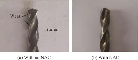
Fig.14 Surface quality of drill bit with and without NAC.
We used the same two drill bits to drill 8 mm thickness Ti 10 times;the spindle-rotation speed is 1000 r/min.We then compared the two drill bits and found that the surface of the drill bit in Fig.14(a)was burned severely and a slight smoking and penetrating smell could be noticed during the drilling process using ordinary drilling.However,the surface of the drill bit in Fig.14(b),which was used in the robotic drilling with the NAC,remained in good condition except for some coating flakes.Obviously,the robotic drilling with the NAC can prolong the service life of the drill bit and decrease the processing costs.
6.Conclusions
This paper presents a newly designed aero-robotic drilling end effector with an intelligent normal adjustment cell.The major components of the NAC system include an intelligent doubleeccentric disk normal adjustment mechanism(2-EDNA),a spherical plain bearing to constrain the adjustment motion,and a floating compress module with three laser sensors to detect the surface normal vector.In addition,five other sensors are used to monitor thefeeding distance for all the postures.
After the floating compress module was fitted to the drilling surface,the surface normal vector was calculated based on the three laser’s feedback.Based on the units surface’s normal vector,the rotation angle α and β of two PEDs of the 2-EDNA can be obtained,although the angle calculation is dependent on the actual initial position.Once the two high-resolution DC servomotors drive the two PEDs to rotate with appropriate angles,the spindle will be considered as coinciding with the surface normal,keeping the vertex of the drill bit still to avoid repeated adjustment and position compensation.2-EDNA is responsible for the normal adjustment of the spindle,which can realize an adjustment of ±5°around the spindle.Two absolute encoders and one tilt sensor are used to achieve closed-loop control for accuracy.
Three groups of experiments were applied to proving that the NAC system can improve the drilling quality by decreasing the drilling force,and Al,Ti,and CFRP were selected as the commonly used aeromaterials.The processing parameters,including the bore diameter and thicknesses were chosen for application requirements.The results show that the tolerance of the bore diameter for all three conditions decreased significantly with the NAC optimization.In the drilling force analysis,we took 6 mm thick Al as a sample,and the result showed that the radial force Fx,the tangential force Fyand the maximal axial force Fzappeared significant reduction for the robotic drilling using the NAC,and the force during the whole process also became smoother.Further microstructure images of the Al drilling hole wall with and without the NAC proved that the heating effect is less with the NAC technology.The average height of the exit burr for Al and Ti was also tested,and it was halftime shorter when adjusted.With less force and a lower temperature,better surface quality of the drill bit was maintained with the NAC.All the experiment analyses indicate that the NAC policies presented in this paper showed obvious superiority compared with the ordinary methodology,and better safety and fatigue life can be achieved with the connecting holes.
Compared with the first version of the drilling system,the new spherical plain-bearing design,which allows for motion adjustments and is optimized for the spindle’s structure,provides better drilling stability during drilling processes especially after long periods of use.Moreover,the floating compressmodule design made the laser-feedback data more reliable for large-curvature objects,thereby increasing the number of possible applications.
With this compact and dexterous NAC system,the whole end effector becomes light,weighing only 60 kg,and becomes stable and accurate at the same time.More test is required and the next step in the research is to prove the properties of more materials with different diameters and thicknesses,including the laminated materials processing parameters.Also,the service life of the equipment needs a longer duration of use to prove the results.
Acknowledgments
This research is partially supported by the National Natural Science Foundation of China(No.61375085),the Postdoctoral Science Foundation of China(No.2014M560872),and the Fundamental Research Funds for the Central Universities(No.YWF-14-JXXY-009).
1.Bakuckas JG,Bigelow CA,Tan PW.Characterization of fatigue behaviour of aircraft fuselage structure.Proceedings of the 22nd symposium of the international committee on aeronautical fatigue;2003 May 5–9,Lucern,Switzerland;2003.p.5–9.
2.Proppe C.Probabilistic analysis of multi-site damage in aircraft fuselages.Comput Mech 2003;30(4):323–9.
3.Rahme´P,Landon Y,Lachaud F.Analytical models of composite material drilling.Int J Adv Manuf Technol 2011;52(5):609–17.
4.Kyle AJ.Enhanced robotic automated fiber placement with accurate robot technology and modular fiber placement head.SAE Int J Aerosp 2013;6(2):774–9.
5.Brewer WD,Bird RK,Wallace TA.Titanium alloys and processing for high speed aircraft.Mater Sci Eng 1998;243(1–2):299–304.
6.Pecat O,Brinksmeier E.Low damage drilling of CFRP/titanium compound materials for fastening.Procedia CIRP 2014;13:1–7.
7.Bi SS,Liang J.Robotic drilling system for titanium structures.Int J Adv Manuf Technol 2011;54(5):767–74.
8.Henderson AJ,Bunget C,Kurfess TR.Cutting force modeling when milling nickel-base superalloys.Proceedings of ASME international conference on manufacturing science and engineering;2010 October 12–15,Pennsylvania,USA;2010.p.193–202.
9.Turki Y,Habak M,Velasco R,Abourab Z,Khellilb K,Vantommea P.Experimental investigation of drilling damage and stitching effects on the mechanical behavior of carbon/epoxy composites.Int J Mach Tools Manuf 2014;87:61–72.
10.Eneyew ED,Ramulu M.Experimental study of surface quality and damage when drilling unidirectional CFRP composites.J Mater Res Technol 2014;3(4):354–62.
11.Liu DF,Tang YJ,Cong WL.A review of mechanical drilling for composite laminates.Compos Struct 2012;94(4):1265–79.
12.Stone R,Krishnamurthy K.A neural network thrust force controller to minimize delamination during drilling of graphite epoxy laminates.Int J Mach Tools Manuf 1996;36(9):985–1003.
13.Day A,Stanley BD,inventor;The Boeing Company,assignee.Apparatus and method for drilling holes and optionally inserting fasteners,United States patent US 20030221306.2003 Dec 4.
14.DeVlieg R,Sitton K,Feikert E,Inman J.ONCE(ONe-sided cell end effector)robotic drilling system.SAE paper:2002-01-26262.
15.Atkinson J,Hartmann J,Jones S,Gleeson P.Robotic drilling system for 737 aileron.SAE paper:2007-01-3821.
16.DeVlieg R.Robotic trailing edgeflap drilling system.SAE paper:2009-01-3244.
17.Collado V,Arana J and Saenz A.A crawling portable robot for drilling operations in large air frame components.SAE paper:2005-01-3337.
18.White TS,Alexander R,Callow G,Cooke A,Harris S,Sargent J.A mobile climbing robot for high precision manufacture and inspection of aerostructures.Int J Rob Res 2005;24(7):589–98.
19.Marguet B,Wiegert F,Lebahar O,Bretagnol B,Okcu F,Ingvar E.Advanced portable orbital-drilling unit for airbus final assembly lines.SAE paper:2007-01-3849.
20.Wright RS,Erickson CJ,Jimenez JJ,inventor.Burrless flexible track drilling system and method having counterweight tool balancing system.United States Patent US 20080181733.2008 July 31.
21.Boyl-davis TM,Buttrick JJN,Gage RA,Jones DD,Papanikolaou KD,inventor;The Boeing Company,assignee.Flexible track drilling machine.United States Patent US 684328.2005 Jan 18.
22.Oberoi H,Draper A,Thompson P.Production implementation of a multi spindleflexible drilling system for circumferential splice drilling applications on the 777 airplane.SAE paper:2009-01-3090.
23.Zhang LX,Wang XS.Dynamic control of a flexible drilling robot end-effector.The 24th Chinese control and decision conference;2012 May 23–25;Taiyuan,China.Piscataway,NJ:IEEE Press;2012.p.2199–204.
24.Shan YC,He N,Li L,Yang YF.Realization of spindle prompt normal posture alignment for assembly hole making on large suspended panel.International conference of measuring technology and mechatronics automation,2011 January 6–7;2011.p.950–956.
25.Qin XS,Wang WD,Lou AL.Three-point bracket regulation algorithm for drilling and riveting of aerof oil.Acta Aeronaut Astronaut Sin 2007;28(6):1455–60[Chinese].
26.Speller TH,Davern JW,Weaver JP,Andrews MJ,inventor;Gemcor Engineering Corp.,assignee.Five axis riveter and system.United States patent US 5248074;1993 Sep 28.
27.Yamazaki K,Tomono M,Tsubouchi T.Pose planning for a mobile manipulator based on joint motions for posture adjustment to end-effector error.Adv Rob 2008;22(4):411–31.
28.Alam M,Guo CLS,Whetro TR,inventor;The Boeing Company,assignee.Adjustable drilling apparatus and associated method.United States Patent US 7083365B2.2006 Jan 8.
29.Yuan PJ,Gong M,Wang TM,Ma FC,Wang QS,Guo J.Intelligent double-eccentric disc normal adjustment cell in robotic drilling.Found Appl Intell Syst 2014;213:457–68.
Shi Zhenyun is a Lecturer in the School of Mechanical Engineering and Automation at Beihang University.Her main research interests are industrial robot and automatic assembly.
16 June 2015;revised 27 July 2015;accepted 11 August 2015
Available online 23 December 2015
Drilling robot;
Eccentric disk;
Normal adaptive;
Normal adjustment cell;Surface normals
©2015 The Authors.Production and hosting by Elsevier Ltd.on behalf of Chinese Society of Aeronautics and Astronautics.This is an open access article under the CC BY-NC-ND license(http://creativecommons.org/licenses/by-nc-nd/4.0/).
*Corresponding author.Tel.:+86 10 82339432.
E-mail address:itr@buaa.edu.cn(P.Yuan).
Peer review under responsibility of Editorial Committee of CJA.
Production and hosting by Elsevier
http://dx.doi.org/10.1016/j.cja.2015.11.001
1000-9361©2015 The Authors.Production and hosting by Elsevier Ltd.on behalf of Chinese Society of Aeronautics and Astronautics.
This is an open access article under the CC BY-NC-ND license(http://creativecommons.org/licenses/by-nc-nd/4.0/).
杂志排行
CHINESE JOURNAL OF AERONAUTICS的其它文章
- E ff ect of sodium tartrate concentrations on morphology and characteristics of anodic oxidefilm on titanium alloy Ti–10V–2Fe–3Al
- Eff ect of temperature on corrosion behavior of 3003 aluminum alloy in ethylene glycol–water solution
- Coupling behavior between adhesive and abrasive wear mechanism of aero-hydraulic spool valves
- Cathode design investigation based on iterative correction of predicted profile errors in electrochemical machining of compressor blades
- Eff ect of tube-electrode inner diameter on electrochemical discharge machining of nickel-based superalloy
- Effects of process parameters on mechanical properties of abrasive-assisted electroforming nickel