Coupling behavior between adhesive and abrasive wear mechanism of aero-hydraulic spool valves
2016-11-24ChenYunxiaGongWenjunKangRui
Chen Yunxia,Gong Wenjun,Kang Rui
School of Reliability and Systems Engineering,Beihang University,Beijing 100083,China
Received 8 September 2015;revised 9 October 2015;accepted 26 November 2015 Available online 14 January 2016
Coupling behavior between adhesive and abrasive wear mechanism of aero-hydraulic spool valves
Chen Yunxia,Gong Wenjun*,Kang Rui
School of Reliability and Systems Engineering,Beihang University,Beijing 100083,China
Received 8 September 2015;revised 9 October 2015;accepted 26 November 2015 Available online 14 January 2016
Leakage due to wear is one of the main failure modes of aero-hydraulic spool valves.This paper established a practical coupling wear model for aero-hydraulic spool valves based on dynamic system modelling theory.Firstly,the experiment for wear mechanism verification proved that adhesive wear and abrasive wear did coexist during the working process of spool valves.Secondly coupling behavior of each wear mechanism was characterized by analyzing actual timevariation of model parameters during wear evolution process.Meanwhile,Archard model and three-body abrasive wear model were utilized for adhesive wear and abrasive wear,respectively.Furthermore,their coupling wear model was established by calculating the actual wear volume.Finally,from the result of formal test,all the required parameters for our model were obtained.The relative error between model prediction and data of pre-test was also presented to verify the accuracy of model,which demonstrated that our model was useful for providing accurate prediction of spool valve’s wear life.
1.Introduction
Aero-hydraulic spool valves are units of the aircraft hydraulic subsystem which plays a critical role in controlling system to work at a normal pressure.They have been the indispensable precision equipment in modern aircraft applications,and their advantages are prominent such as high accuracy for controlling,fast dynamic response,and long service life.1Failures originated by spool valves can impose a direct effect on the performance of hydraulic subsystem.Thus,researchers have been doing a lot of studies on dynamic performance or failure analysis about spool valves during recent years.2,3According to statistics,failures resulted from the spool valve wear account for more than 22%of the total failures of control valves.The repair time takes up more than 20%of the total repair time.4,5There fore,it is necessary for these spool valves to have an accurate wear model to support wear resistance research for a longer running time.
Previous studies reveal that oil leakage due to the wear process is one of the main failure modes of aero-hydraulic spool valves.However,most of them simply consider establishing the loss function due to hydraulic clamping and pollution clamping regardless of original reasons for this failure phenomenon.6,7With this problem,some papers are presented to truly focus on the particle erosion wear which is the main failure cause of electrohydraulic servo valves(EHSV).8In addition,researchers have qualitatively analyzed the contribution of erosion wear to the performance degradation of sliding spool.Meanwhile,a lot of erosion wear models are established to predict an accurate wear life for EHSV.9,10However,it is only practical for just a single kind of erosion wear mechanism.Actually,different spool valve material,working stress or lubrication condition can induce other different wear mechanisms to cause hydraulic spool valve failures that need us to reveal,such as adhesive wear,abrasive wear,or their combination.
From analysis of working condition and dynamic characteristic about spool valves,we can see that sliding wear behavior is the main dynamic characteristic of aero-hydraulic spool valve.So the wear evolution process may be determined by several wear mechanisms(i.e.fatigue,abrasive,adhesive,corrosive).11And these involvements and their interactions and competitions produce a complex wear evolution progress which varies significantly with respect to the topographical and tribological changes of surface.Thus,a dynamic wear model is needed to reflect continuous two-way feedback between contact mechanism and dynamic mechanics processes over the spool valve’s lifetime.
Dynamic wear modelling for the wear evolution process has been proved to be effective for many complicate time-variation systems.12The initial dynamic method about wear was utilized in rolling wear area.El-Thalji and Jantunen13concluded its drawbacks about previous work in their paper and developed another effective dynamic modelling method of wear evolution in rolling bearings;it can explain different wear mechanisms among the wear evolution stages.And Ma et al.14considered the friction coefficient evolution during sliding wear.Besides,some other combinations of different wear behaviors were studied.15–17But most work just focused on the actual evolution process,failing to consider the wear prediction for engineer practices.However,traditional wear prediction models for sliding wear behavior can only be developed for a single wear mechanism,just like Archard model,18three body abrasive wear model19and so on.Thus,it is necessary to propose a new model which can be just suitable for coupling wear mechanisms.Based on the analysis of most wear models,Meng and Ludema20concludedthatagoodwearmodelshouldavoidtheperpetuationof erroneous and subjective expressions for the mechanisms of wear.Thus,inthispaper,ourmodelisproposedbasedonactual wear process and their effects on contact surface.
The aim of this paper is to establish a practical coupling wear model for aero-hydraulic spool valve.According to the experiment for wear mechanism verification,adhesive wear and abrasive wear mechanisms do coexist during the working process of spool valve.Then,Archard model and three-body abrasive wear model are utilized for describing adhesive wear and abrasive wear mechanisms.Besides,the coupling mechanism relationship is determined by analyzing each mechanism characteristic.And a coupling wear model is established by calculating the actual wear volume.Finally,from the result of spool valve tests,all the required parameters for our model are obtained.To verify the accuracy of model,the relative error between model prediction and actual test is presented,which demonstrates that our model is useful for providing accurate prediction of spool valve’s wear life.
2.Experiment for wear mechanism verification
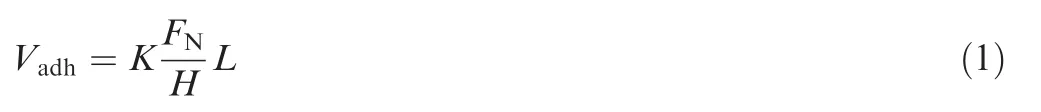
A specific aero-hydraulic spool valve was selected to verify the contact between the spool and the valve sleeve and to ensure the compatibility of the results with the real working application.Besides,actual conversion-sliding tests were used to investigate the wear mechanism during actual working process.The aero-hydraulic spool valve observed is presented in Fig.1.
The tests of spool valve were implemented on the test plat form(Fig.2).Ten samples satisfy our requests.One is used for pre-test,and the other nine samples are used for model parameters identification which will be introduced in Section 5.
The initial state of the spool shoulder surface by the observation of scanning electron microscope(SEM)is smooth(Fig.3).After 10000 conversions,the SEM is utilized to observe the same place of the spool shoulder.We can figure out that different wear behaviors happened between two contact surfaces.In Fig.4,shearing and trans formation of material can be seen due to the shear fracture of adhesion points.It can work as a proof of the adhesion wear mechanism between spool and valve sleeve.Meanwhile,furrow on the surface of the spool shoulder can be also observed in Fig.5,which is caused by pressure and relative sliding of three-body abrasives.In summary,according to the SEM observation results of spool valve shoulder,adhesive wear and abrasive wear coexist in the wear evolution process of aero-hydraulic spool valves.
3.Wear model description
3.1.Adhesive wear model
The spool and valve sleeve of aero-hydraulic valve are made of the same material.High contact pressure on the contact point causes the adhesion of metals.Furthermore,it can lead to the adhesive wear between spool and valve sleeve.There fore,it is necessary to consider adhesive wear model.Archard wear model is widely applied in the calculation of adhesive wear under dry sliding condition.It takes the form18
where Vadhrepresents the adhesive wear volume,K the wear coefficient,FNthe normal load,H the material hardness,and L the wear stroke distance.In fact,the normal load between spool and valve sleeve is the asperity load due to the coordinate intervals.So we replace FNwith the asperity load Wa.Besides,the spool valve works in a mixed lubrication condition,while adhesive wear can only take place in metal-tometal contact points.Thus,a fractional film defect index β is introduced into Archard wear model,which is represented by21
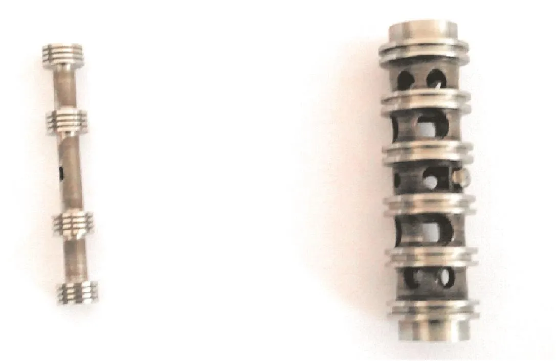
Fig.1 Aero-hydraulic spool valve.

Fig.2 Test plat form for spool valves.
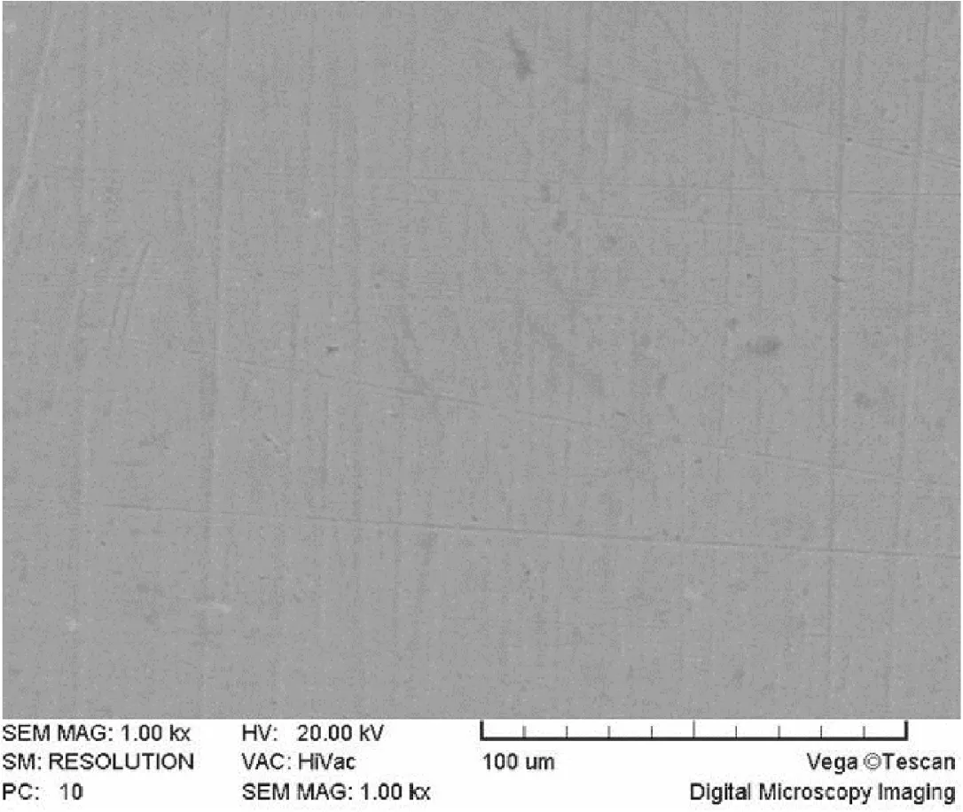
Fig.3 Initial state of spool shoulder surfacefrom SEM results.
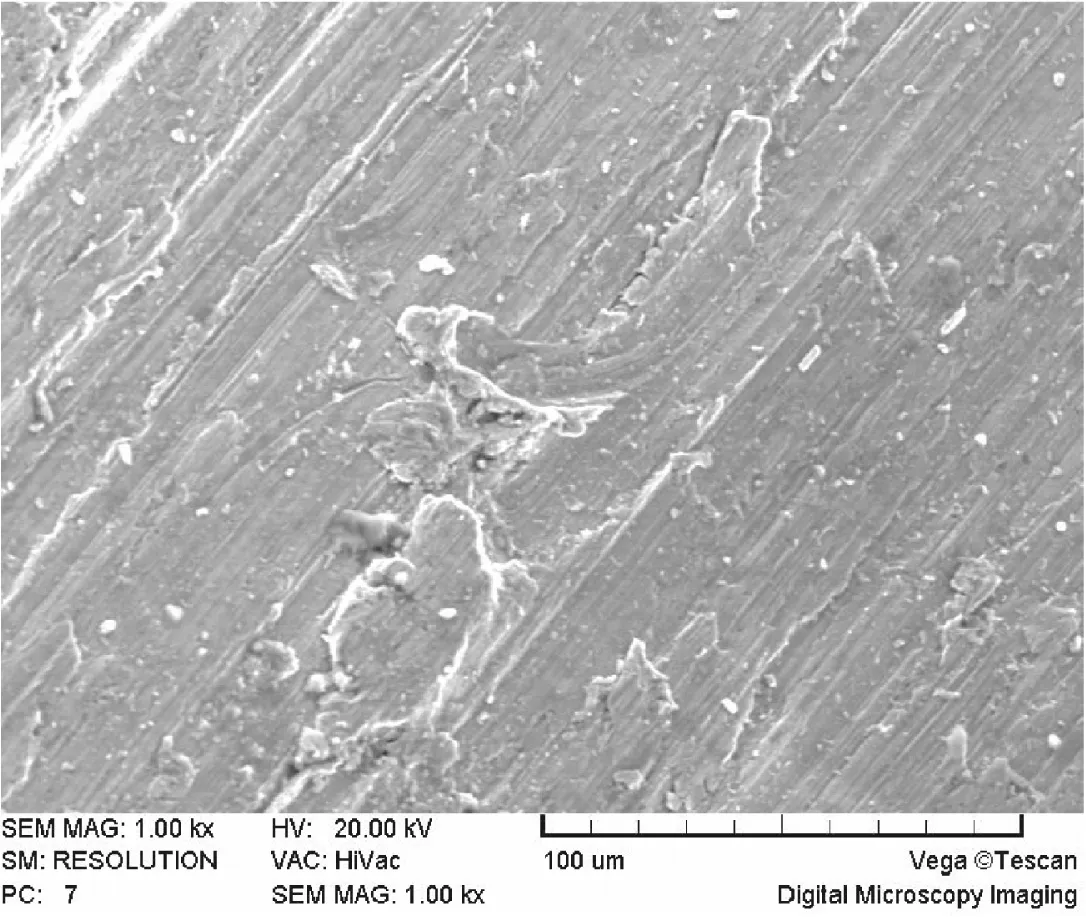
Fig.4 Adhesive wear featurefrom SEM.

Fig.5 Abrasive wear featurefrom SEM.

From Eq.(2),we can get that wear is the process in which material overcomes the mechanical engagement and the molecular attraction of surface asperities.There fore,friction is a sum of the mechanical engagement force and the molecular attraction force,which will be discussed later.
3.2.Abrasive wear model
Three body abrasive wear is a typical wear mechanism about relative movement of abrasive particle between two contact surfaces.From Ref.21,we can see that two terms are included:the cutting mechanism and plastic mechanism(Fig.6).Based on the result of Ref.22,the micro cutting mechanism accounts for a tiny little ratio in the whole wear process.Thus,it is suitable to choose an abrasive wear model which is based on plastic theory.23
And the three-body abrasive wear model can be represented by
where Vabris the abrasive wear volume and W the normal load on three-body abrasive.Based on the load analysis of spool valve,abrasive particles generate a settlement effect under its own gravity.Thus,most of the abrasives happen in the bottom of the contact area between the spool and valve sleeve.Generally,the value of W can be determined by the gravity of spool that equals to mxg where mxis the mass of valve sleeve,and g the acceleration of gravity which generally equals to 9.8 N/kg.In most cases,the lubrication fluid dynamic effect can be neglected if the impact on the normal load is very little.Hmis the hardness of contact surface.Kabris the abrasive wear coefficient.It can be calculated with the consideration of contact and wear evolution process,and some details would be presented in Section 3.3,which precisely reflects the surface changing or lubrication oil feature.
3.3.Material and parameter identification
In this section,the procedure for identifying the parameters of aforementioned adhesive wear model and abrasive wear model is presented.
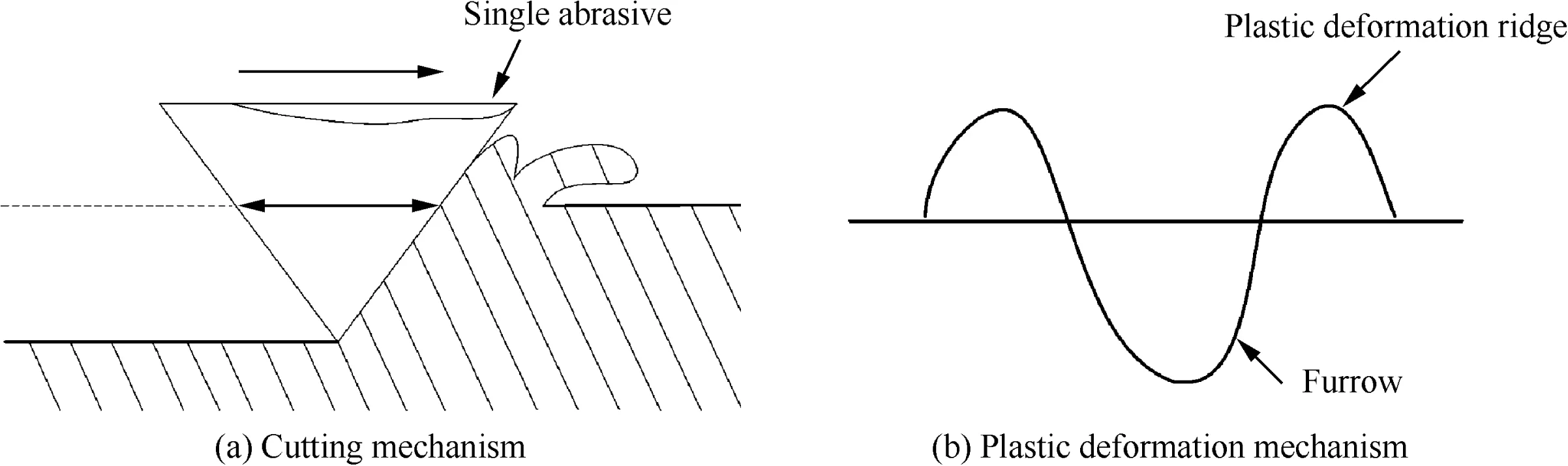
Fig.6 Different mechanism about abrasive wear.
3.3.1.Asperity load Wa
Be fore calculating the asperity load,we need to figure out surface roughness degree.Commonly,surface textures can be described in terms of distribution function of the profile height.The surface morphology includes the part of fixed period variety and the part of probability variety.A probability density function for asperity heights φ(z)is proposed to describe the probability of locating a point on the surface at height z.The most commonly used probability distribution function(PDF)is Gaussian distribution which is given as24
where σ is the variance of z,i.e.,the root mean square(RMS)roughness.Based on Eq.(4),both PDFs of valve sleeve and spool surfaces can be obtained,which are represented by φx(z)and φt(z),respectively.
Besides,the contact of two randomly rough surfaces of spool and valve sleeve can be equivalently trans formed into the contact of a rigid smooth surface and a composite elastoplastic rough surface(Fig.7).It can be described as25

where σxrepresents RMS roughness of valve sleeve surface and σtRMS roughness of spool surface.Then PDF of the equivalent composite elastoplastic surface can also been calculated,which is represented by φs(z).
From Fig.7,we can see that only if z≥h,contact between two surface can happen.h is assumed to be the distance between the profile centerlines of two mating surfaces.Based on the GW contact model,26we assume that each rough asperity has the same radius of curvature.Each de formation of asperities assumes to be s-independent.Thus,the plasticde formation only happen when the asperity height z obeys21
where R is the radius of asperity of equivalent rough surface,δpthe value of critical normal de formation as the plastic de formation of micro convex body appears,and E′the elastic modulus of equivalent rough surface.Considering that materials of spool and valve sleeve are the same,E′can be obtained by26
where Ex,Etare elastic moduli of valve sleeve and spool respectively,and μx,μtpoisson ratios of valve sleeve surface and spool suface respectively.
Assume that each unit area of equivalent rough surface has n asperities.If h<z<h+δp,asperities take an elastic de formation;or else if z≥h+δp,asperities take a plastic de formation.Thus,the asperity load Waconsists of two parts:one is the load Wein the elastic de formation stage;the other is the load Wpin the plastic de formation stage.It can be represented by21
3.3.2.Fractional film defect index β
Generally,β is determined by the adsorption and desorption capacity of oil molecules on the surface of friction pair during the relative motion process.From Ref.28,we can see that it can be defined by Am/Ar.By this way,Aris the contour contact area(including oil film contact area and mental to metal contact area),and Amis the metal to metal contact area.During the relative motion process of friction pair,the main factors that affect lubrication are oil temperature and relative motion velocity v of friction pair.It is described in Fig.8,where Q represents the upper surface,and S the lower surface.
Stolarski27has presented the calculation formula if fractional film defect index β is under single lubricant condition
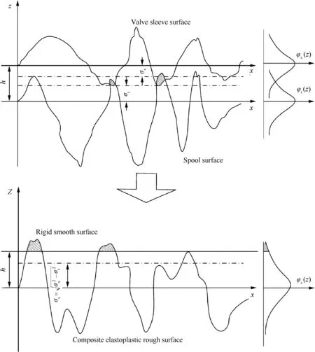
Fig.7 Equivalent trans formation of two surfaces.

Fig.8 Influence of relative motion velocity on β.
where tzis the time consumed by the asperity slides through the equivalent distance of oil molecular diameter,and trthe average adsorption time of an oil molecular on a certain point of the contact surface.The time tzcan be calculated by


where T is oil temperature,t0the oscillation period of an adsorbed oil molecular on the contact surface,Ecthe adsorption energy of oil molecular,and Rsthe gas constant.Combining Eqs.(9)-(11),thefractional film defect index β can be expressed as

where d1and d2are parameters to be estimated in Section 5.
3.3.3.Adhesive wear coefficient Kadh
The empirical relationship between adhesive coefficient Kadhand friction coefficient f can be described as21

Thus,the main work will focus on derivation of friction coefficient f.Wear is the process in which material overcomes the mechanical engagement and the molecular attraction of surface asperities.There fore,friction Fμis sum of both parts above.And we can get its expression as21

The friction coefficient can be obtained by Coulomb’s law

where Sfis tangential resistance of molecular effect,Bfthe influence coefficient of surface roughness,Bjcoefficient of normal load effect,and γ proportionality constant.Through simplification,we can get that τ0/pr+ βmis the molecular component,where τ0represents the friction force generated by the molecular interaction on the unit area and βmthe molecular bond enhancement factor.αpris the mechanical component,where α equals to γBj/1+ γ and prequals to Wa/Am.Amis the value of real contact area,and it can be obtained as Eq.(16)shows.
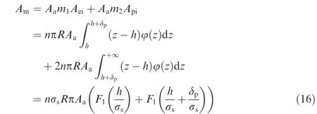
where Aeiis the contact area of single asperity at elastic de formation state which equals to πR(z-h),and the number is assumed to be m1that equals to n∫h+δphφ(z)dz.Similarly,Apirepresents the contact area of single asperity at plastic de formation state which equals to 2πR(z-h),and the number is assumed to be m2that equals to n∫+∞h+δpφ(z)dz.
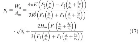
Thus,based on Eqs.(8)and(16),the expression of prcan be represented by
Combining Eqs.(13),(15)and(17),we can obtain the following equation
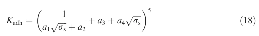
where a1,a2,a3,a4are the positive coefficients,and they are related to material physical and chemical properties and lubrication condition about spool valve.The calculation forms about these four coefficients can be deduced by the above formulas.
3.3.4.Abrasive wear coefficient Kabr
From the three-body abrasive wear model,we can see that it is a situation where only the plastic de formation is considered.Thus,based on this assumption,we can get the expression of Kabras30
where E is the elastic modulus of spool valve that equals to Exor Et;θ is the abrasive cone semi angle,and the value is determined by the sharpness of abrasives.Based on the experimental analysis from other scholars30,if the abrasive material is SiO2,θ equals to 80°,and in this case,the main part is SiO2in the hydraulic oil pollution of the spool valve during the working state,thus,tanθ equals to 5.67.K0represents the abrasive rate coefficient of relative movement.Similarly,based on the result of experiment from other scholars,30if the friction pair in the low speed movement condition(the sliding speed v≤ 0.3 m/s),the value of K0can equal to 3.3tanθ,which just satisfies our case. So it can be determined by K0=3.3tanθ=18.71.K1is the abrasive sliding scale factor,and considering that the spool and vale sleeve are made of the same material which is alloy steel,the value of K1is 0.5 from Ref.30.K2is the abrasive concentration coefficient,and it depends on the number of abrasive that participates in wear process.If the contact surface is filled with the abrasive grains,K2equals to 1;if there is no abrasive between two contact surfaces,K2equals to 0.In our case,most of abrasive grains are gathered at the bottom position of friction pairs,which is the situation of high contact.Thus,the value of K2is assumed to be 0.33 from Ref.30.K3is the abrasive grain size coefficient,and it can be calculated by K3=da/dc(0 < K3≤ 1),where dais the height of abrasive grain,and dcis the critical abrasive height.If da>dc,K3equals to 1.Based on the experimental result of Misra and Finnie,31the value of dcequals to 0.16×10⁻³mm.The minimum permissible clearance that can enter into the contact gap of spool valve is 0.001 mm.Thus,in our case,K3equals to 1.K4is the abrasive relative hardness coefficient.If Ha/Hm≤2,and material of surface is steel,K4can be determined by K4=1/[5.5- (Ha/Hm)2.2].The material of spool valve in our case is alloy steel,and main part of abrasive is SiO2.The hardness of abrasive grain Hais HV 1000,and the hardness of spool valve Hmis HV 589;thus,we can get that K4equals to 0.42.K5is the lubrication coefficient,and the interval of K5is (0,1].In our case,the lubrication mode is oil lubrication.Based on the result of experiment from Wang YL and Wang ZS,30the value of K5is assumed to be 0.75.
4.Coupling behavior analysis of double wear mechanisms
In this paper,the relationship between these two models and actual wear process should be discussed.Through analysis of the variation of wear mechanism,coupling characteristic can be defined as the parameters and functions which can be described in the wear models.
During the wear evolution process of the spool valve,variation process can be separated into two terms:furrow process and truncation process.These two processes both have an impact on surface roughness.The analysis is described in Fig.9.
From Fig.9,we can see that truncation process can induce the cutting action of single asperity on the surface during contact and sliding process.Furrow process is the result of three body abrasives sliding on the contact surface.Their impacts on surface roughness and wear volume should be quantified as a fixed function.Thus,in this section,the dynamic wear model can be described as

where V is the total wear volume.Similarly,the comprehensive RMS roughness rate of surface is a sum of roughness rates caused by truncation process and furrow process.It can be determined as
where σs(tp)is RMS roughness during truncation process,and σs(pp)RMS roughness during furrow process.The following work will focus on the calculation about their variations on surface roughness.
4.1.Variation of surface roughness σs(tp)in truncation process
Based on the assumption that contact of two random rough surfaces is equivalently trans formed into a rigid smooth surface and a composite elastoplastic rough surface,peaks of asperities will be cut of f during the truncation process and the distribution function of the surface profile height will continuously change with time.
We suppose that probability density function of profile height z of rough surface at time t is φ(z,t),where φ(z,0)is known as the initial state.w(z-h)is the asperity wear ratefunction.It means the reduction of profile height z per unit time,or asperities having a embed depth of (z-h).According to Ref.25,we can get that
RMS roughness σs(tp)of equivalent rough surface can be described as
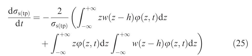
Taking derivative with respect to time t on both sides of Eq.(23),we can obtain

Besides,it is proved by Misra and Finnie,31when z→∞,φ(z,t)is the higher-order infinitesimal of 1/(z2w(z-h)).Combing the definition of wear ratefunction which is dz/dt=-w(z-h),Eq.(24)can be simplified to
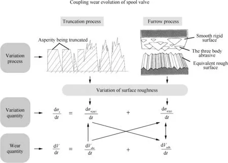
Fig.9 Coupling behavior analysis of wear mechanisms.
We suppose that the wear rate function can be shown as32
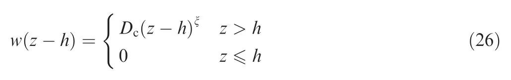
where ξ is an exponent characterizing the degree of asperity de formation,and Dca coefficient associated with wear rate of thefriction pair,and we can obtain

where the coefficient C>0,and x is the wear depth.The relationship between the volume wear rate and line wear rate can be indicated as
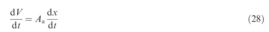
Substituting Eq.(28)into Eq.(27),we can obtain

And Eq.(25)equals to

If we take ξ=1,which means that asperity wear velocity and the embed depth of asperity follow a linear relationship,we can obtain

where b1,b2,b3(b1< 0,b2< 0,b3> 0)are unknown parameters that need to be estimated.From Eq.(32),we can see that the variation of surface roughness caused by the truncation process obeys exponential type.The RMS of surface will decrease with time and finally reach a stable value of -b2.
4.2.Variation of surface roughness σs(pp)in furrow process
Thefurrow process caused by three-body abrasive will result in the variation of the surface roughness.Similarly,we suppose that contact of two random rough surfaces is equivalently trans formed into the contact of a rigid smooth surface and a composite elastoplastic rough surface.Abrasives are assumed to be rigid cones,which cannot be crushed during the wear process and are distributed evenly in the contact area.The three-body abrasives can move in the gap of spool valve with the lowest energy state.Thus,the moving distance during single working period for the three-body abrasive is not identical with the wear distance of the smooth rigid spool surface.
We suppose that profile height functions of abrasive and rough surface at time t are Za(t)and Zs(t),respectively(Fig.10).
The profile height function at time t+Δt during the three body wear process can be obtained by

The distribution function of profile height FZs(t+Δt)(z)at t+Δt is
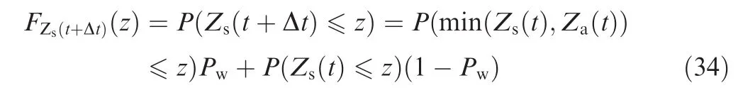
where Pwis the probability that abrasive wear happens,and it equals to the value of K1in this case.Based on the independency between Za(t)and Zs(t),we can obtain
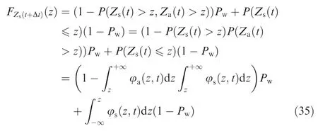
where φa(z,t)and φs(z,t)are probability density functions of abrasive profile height and rough surface profile height at time t.Besides,abrasives cannot be crushed during the wear process;thus, φa(z,t)will not change with time,and Eq.(35)becomes


Fig.10 Variety of profile height caused by furrow process.
The probability density function of profile height φs(t+Δt)(z)at t+Δt is showed as

The profile height of equivalent rough surface obeys a Gaussian distribution at the situation that t=0,and we have3
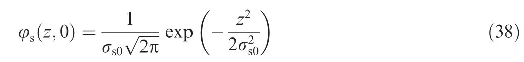
where σs0is the initial RMS roughness of equivalent rough surface.The particle size distribution of abrasive in oil obeys a fold normal distribution as
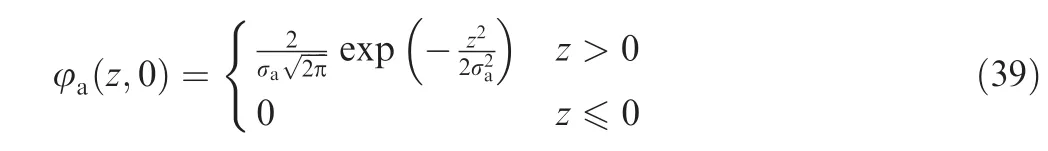
where σais the RMS roughness of abrasive.According to the definition of RMS roughness,σs(t+Δt)can be determined as
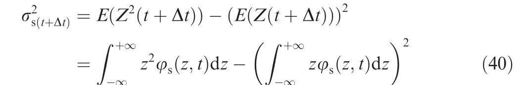
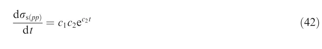
With Eqs.(37)-(40),numerical solution for σscan be obtained at any time under the given initial condition.We can see that furrow process makes the value of σsdecrease with time t smoothly,just as the exponential model shows,thus,it can be described as

where c1,c2(c1> 0,c2< 0)are parameters that need to be estimated.And Eq.(41)can be trans formed into
4.3.Determination of coupling wear model
Based on the whole result of derivation process,we can obtain the semi-empirical formulation for wear prediction.As Eq.(20)shows,the total spool wear rate is a sum of adhesive wear rate and three-body abrasive wear rate.Combining Eqs.(2),(8),(12),(17),the revised adhesive wear rate based on Archard model can be described as
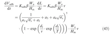
Similarly,combining Eqs.(3)and(19),the three-body abrasive wear rate based on the plastic de formation theory is presented as

In summary,the coupling wear model in our paper is the first order bivariate dynamic wear model.The whole wear volume prediction can be calculated as

According to Eqs.(21),(32)and(42),it can be speculated that the variation of the comprehensive RMS roughness σsobeys an exponential type.Thus, for simplification,the equation can be assumed to be

where q1,q2(q1> 0,q2< 0)are parameters to be estimated in Section 5.
5.Model parameters identification and validation
In this section,we need to figure out the accurate wear model to predict wear volume of spool valve.It includes two parts:model parameter identification and validation.The spool valve tests are divided into pre-test and formal test.The data of the formal test are used to identify model parameters,while the data of the pre-test are used to validate the wear model.Details about experiment can befound in Section 5.1.
5.1.Experimental parameters determination
The aero-hydraulic spool valves for pre-test and formal test are the same,which is the key component of aileron control actuator.The working stresses of spool valve that we can control are conversion rate v and oil temperature T.Conversion rate v represents the rotary sliding speed between spool and valve sleeve which can be determined by input oil pressure p.Actually,the relationship between conversation rate and oil pressure cannot be described as an existing function with fixed variables.Thus,in this case,the value of conversion rate v can only be calculated by v=s/t,through measuring the actual rotary sliding distance s and the corresponding time t when the oil pressure is fixed.Considering the limited test ability of test plat form,we choose three monitoring points with different values of oil pressure(Table 1).
The sample size for the whole test is ten spool valves.One is for the pre-test;the other nine are for the formal test.The pretest is a constant stress test,and the working stress level is T=323 K,p=21 MPa.Because a single conversion time of the spool valve is settled,the actual test time can be trans formed by recoding the number of conversion,and the detecting points for pre-test include 0,100,500,1000,2000,2500,3000,3500,4000,4500 and 5000.Meanwhile,the stress levelsof the formal test are divided into nine groups.Each group has the same detecting point(Table 2).

Table 1 Relationship between oil pressure and conversion rate.

Table 2 Stress level and detecting point arrangement of formal test.

Table 3 Experimental parameters provided be fore and after tests.
In Section 5,a practical wear prediction model for the aerohydraulic spool valve needs to be established based on the data of formal test.Thus,we need to acquire the actual wear volume V and RMS surface roughness σsat different stress levels and corresponding time points.The testing method of wear is the weighing method,33which is applicable for engineering systems.Some details about this method can befound from Ref.33.The RMS surface roughness σscan be measured by the surfagauge.Some other experimental parameters are provided be fore and after tests(Table 3).
5.2.Coupling dynamic wear model parameters determination
To guarantee that the proposed calculation model can be practical,we need to confirm each model parameter with the speci-fic features of the aero-hydraulic spool valve.The main parameters of our coupling wear model in Eq.(45)are shown in Table 4.
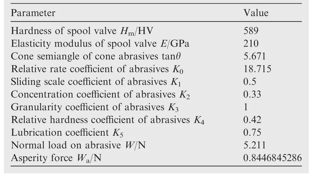
Table 4 Main parameters of aero-hydraulic spool valve wear model.

Table 5 Results of parameter estimation for coupling wear model.
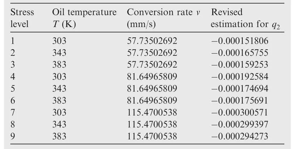
Table 7 Revised estimation results for parameter q2at each stress level.
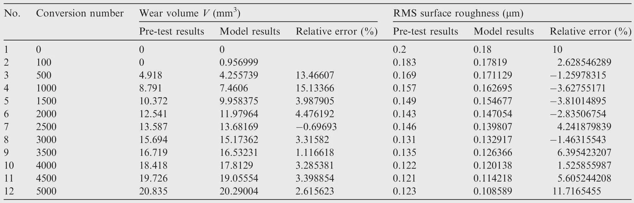
Table 8 Comparisons between pre-test results and coupling wear model results.
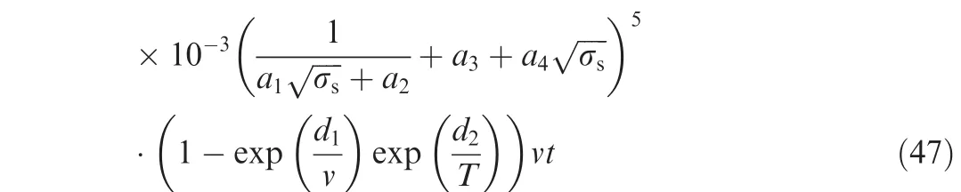
Combining Eq.(45),the remaining work will focus on the estimation of parameters including a1,a2,a3,a4,d1,d2,q1,q2as shown in Eqs.(46)and(47).V=2.58943×10⁻⁶vt+1.53579
Based on the data of formal test,the wear volume V,conversion rate v,test time t,RMS surface roughness σsand oil temperature T can be obtained as the input data for parameter estimation.The main results of nonlinear fitting work are presented in Table 5.The fitted relation coefficient for this fitting result equals to 0.898,which proves that we achieve a reasonable accuracy.
Besides,the estimation values for parameters q1and q2at each stress level can also be obtained(Table 6).
Now that q1is a constant which is irrelevant to stress level,it can be assumed to be the average of these nine estimation values in Table 7.Thus,the value of q1can be obtained as Eq.(48)shows,while q2is a function of conversion rate v and oil temperature T that should be re-estimated.

Then,taking the new value of q1into Eq.(46)and combining with the value of σsat each stress level,we can calculate a new estimation result for q2(Table 7).
Based on the data of Table 8,in this case,a power law model is considered to be the fitting function for the estimation as Eq.(49)shows.

The estimated results are^l1=-4.61 × 10⁻⁶,^l2=-0.12,=1.02.Thefitted relation coefficient for this fitting result equals to 0.919,which demonstrates that we achieve a reasonable accuracy.
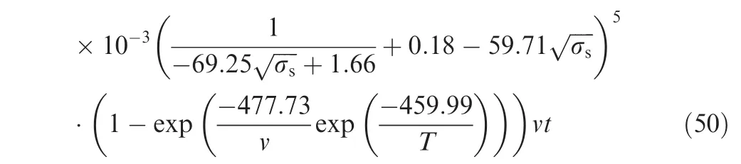
Finally,eight different parameters are provided to obtain the expressions of the coupling wear model.The formulations of wear volume can be described as
V=2.58943×10⁻⁶vt+1.53579
The RMS roughness of contactsurfaceσscanbedescribedas

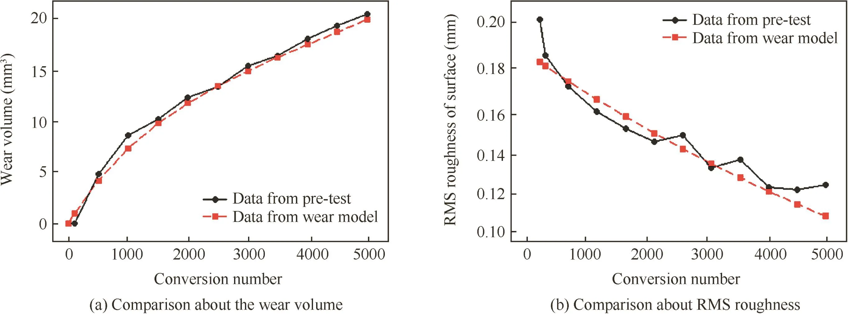
Fig.11 Comparsion between pre-test results and wear model prediction.
From Eqs.(50)and(51),the wear volume with different oil temperature T and conversion rate v can be calculated to predict actual wear process of spool valve.
To con firm the validity of the proposed wear prediction model,pre-test has been per formed which is working at different stress level.Compared to the data of spool valve wear process in pre-test,the difference between them has been presented with relative errors(Table 8).Thereafter,we record the guidefitting curves to make it clear(Fig.11).
From Fig.11(a),we can see that the rate of wear of the aero-hydraulic spool valve in the first 1000 conversion times increases faster than that in the following phase.Moreover,the measured and predicted results based on Eqs.(50)and(51)have the same change trend and similar magnitude of change;thus,the established wear prediction model can correctly describe the change in the coupling wear evolution process of the aero-hydraulic spool valve under loading.
6.Conclusions
In this paper,a coupling wear model is established to analyze coupling relationship between adhesive wear and three-body abrasive wear for the aero-hydraulic spool valve.The research achievements gained in this paper are as follows:
(1)The pre-test data strongly verify that wear mechanisms during the life period of aero-hydraulic spool valve consist of adhesive wear and abrasive wear,which provides the evidence support for coupling wear study.
(2)The coupling behavior analysis of these two wear mechanisms has been presented to describe the actual wear evolution process between surfaces of spool and valve sleeve.The roughness parameters are utilized to convey the interaction between truncation process and furrow process,which can be the input parameters for the wear model.
(3)A practical coupling wear model for aero-hydraulic spool valve is established.Meanwhile,the data of pretest also demonstrate that our model has a practical foreground for engineering.
Our paper provides a new direction for the mechanism coupling modelling and promotes the research on the mechanism coupling study.Coupling modelling is complex,and different mechanisms have their own unique coupling relations.Actually,there is not a universal method to take the whole failure mechanism into consideration.Thus,many other mechanism relationships need to be revealed for engineering practice.
1.Dasgupta K,Murrenhof f H.Modelling and dynamics of a servovalve controlled hydraulic motor by bondgraph.Mech Mach Theory 2011;46(7):1016–35.
2.El-Araby M,El-Kafrawy A,Fahmy A.Dynamic performance of a nonlinear non-dimensional two stage electrohydraulic servovalve model.Int J Mech Mater Des 2011;7(2):99–110.
3.Shujiro D,Tetsuya A,Yusuke M,Hisashi M,Zhang Y.Development of small-sized digital servo valve for wearable pneumatic actuator.Proc Eng 2012;41:97–104.
4.Xu Y.The reason and countermeasures of hydraulic spool valve clamping phenomenon.Lifting Transp Mach2008;10:101–3[Chinese].
5.Chen YX,Jing HL,Liao X,Kang R.Research on the wear mechanism coupling modeling of spool valve.RAMS 2015:Proceedings of 61st annual reliability and maintainability symposium;2015 Jan 23–26.New York,USA;2015.p.1–8.
6.Chen KS,Zhou WJ,Guo Y,Fu SG,Zhang HW,Jiang J.Analysis for clamping force of hydraulic slide-valve spool based on fluent.Mach Tool Hydraul 2011;39(15):113–5[Chinese].
7.Zhang JJ,Liu G,Wang JY.Research on the clamping force of hydraulic slide valve.Mach Tool Hydraul 2014;42(13):71–3 Chinese.
8.Fang X,Yao JY,Yin XZ,Chen X,Zhang CH.Physics-of -failure models of erosion wear in electrohydraulic servovalve and erosion wear life prediction method.Mechatronics 2013;23(8):1202–14.
9.Vaughan ND,Pomeroy PE,Tilley DG.The contribution of erosive wear to the performance degradation of sliding spool servovalves.P I Mech Eng J-J Eng 1998;212(6):437–51.
10.Huang XB,Yao JY,Li Y.Research to the wear and geometric error relations of electro hydraulic servo valve.Proc Eng 2011;15(1):891–6.
11.Bayer RG.Fundamentals of wear failures.In:Becker WT,Shipley RJ,editors.ASM handbook Volume 11.Failure analysis and prevention.Ohio:ASM;2002.p.901–5.
12.Peter WT,Mathew J,Wong K,Lam R,Ko CN,editors.Proceedings of the 8th world congress on engineering asset management,2013Oct30–Nov1,HongKong,China.New York:Springer;2013.
13.El-Thalji I,Jantunen E.Dynamic modelling of wear evolution in rolling bearings.Tribol Int 2015;84:90–9.
14.Ma GJ,Wang LL,Gao HX,Zhang J,Reddyhoff T.The friction coefficient evolution of a TiN coated contact during sliding wear.Appl Surf Sci 2015;345:109–15.
15.Nelias D,Boucly V,Brunet M.Elastic-plastic contact between rough surfaces:proposal for a wear or running-in model.J Tribol-T ASME 2006;128(2):236–44.
16.Morioka Y,Tsuchiya Y,Shioya M.Correlations between the abrasive wear,fatigue,and tensile properties of filler-dispersed polyamide 6.Wear 2015;338–339:297–306.
17.Chand N,Dwivedi UK.Effect of coupling agent on abrasive wear behaviour of chopped jutefibre-rein forced polypropylene composites.Wear 2006;261(10):1057–63.
18.Archard JF.Contact and rubbing of flat surfaces.J Appl Phys 1953;24(8):981–8.
19.Xie XP,Xie YB.Analysis of three-body abrasive wear with fatigue theory.Tribotest 1998;4(3):289–95.
20.Meng HC,Ludema KC.Wear models and predictive equations:their form and content.Wear 1995;181–183:443–57.
21.When SZ,Huang P.Tribology principle.3rd ed.Beijing:Tsinghua University Press;2011.p.155–200[Chinese].
22.Kragelsky IV,Mikhail ND,Viacheslav SK.Friction and wear:calculation methods.2nd ed.Amsterdam:Elsevier;2013.p.88–9.
23.Stilwell NA,Tabor D.Elastic recovery of conical in dentations.Proc Phys Soc 1961;78(2):169.
24.Ghosh A,Sadeghi F.A novel approach to model effects of surface roughness parameters on wear.Wear 2015;338–339:73–94.
25.Golden JM.The evolution of asperity height distributions of a surface subjected to wear.Wear 1976;39(1):25–44.
26.Popov V.Contact mechanics and friction:physical principles and applications.1st ed.Berlin:Springer Scienceamp;Business Media;2010.p.5–10.
27.Stolarski TA.A system for wear prediction in lubricated sliding contacts.Lubr Sci 1996;8(4):315–51.
28.Sun JS.Wear of metal.1st ed.Beijing:Metallurgical Industry Press;1992.p.163–5[Chinese].
29.Hornig DF.Molecular vibrations:the theory of infrared and Raman vibrational spectra.1st ed.New York:Dover Publications;2012.p.45–6.
30.Wang YL,Wang ZS.Analysis and calculation of three-body abrasive wear.J Shanghai Jiao Tong Univ 1986;20(3):40–51[Chinese].
31.Misra A,Finnie I.On the size effect in abrasive and erosive wear.Wear 1981;65(3):359–73.
32.Zhang B,Xie YB.Two-body micro cutting wear model part I:two-dimensional roughness model.Wear 1989;129(1):37–48.
33.Liu YB,Wang HJ,Chen JL,Li X,Xu LC.Research into testing method of wear online.Lubr Eng 2005;3:72–3[Chinese].
the B.S.and Ph.D.degrees in School of Reliability and Systems Engineering from Beihang University(BUAA),Beijing,China in 1999 and 2004,respectively.She is a professor in School of Reliability and Systems Engineering,Beihang University.Her main research interests include reliability design and experiment technology based on physics of failure,integrating design for performance and reliability.
Gong Wenjun is a Ph.D student in School of Reliability and Systems Engineering,Beihang University,Beijing,China.His current research interests include degradation modeling,imperfect maintenance policy and reliability assessment.
Kang Rui received the B.S.and M.S.degrees in School of Automation Science and Electrical Engineering from Beihang University(BUAA),Beijing,China in 1987 and 1990,respectively.He is a chair prof essor in School of Reliability and Systems Engineering,Beihang University.He is a Yangtze River Scholar of China.He has developed six courses and published five books and more than 100 research papers.He is an expert in reliability in technology and industry of China.His main research interests include reliability design and experiment technology based on physics of failure,prognostics and health management(PHM)and network reliability.He received several types of award from the Chinese government for his outstanding scientific research.
Abrasive wear;
Adhesive wear;
Aero-hydraulic spool valves;
Coupling effects;
Dynamic model
©2016 The Authors.Production and hosting by Elsevier Ltd.on behalf of Chinese Society of Aeronautics and Astronautics.This is an open access article under the CC BY-NC-ND license(http://creativecommons.org/licenses/by-nc-nd/4.0/).
*Corresponding author.Tel.:+86 10 82338909.
E-mail address:gongwenjun@buaa.edu.cn(G.Wenjun).
Peer review under responsibility of Editorial Committee of CJA.
Production and hosting by Elsevier
http://dx.doi.org/10.1016/j.cja.2016.01.001
1000-9361©2016 The Authors.Production and hosting by Elsevier Ltd.on behalf of Chinese Society of Aeronautics and Astronautics.This is an open access article under the CC BY-NC-ND license(http://creativecommons.org/licenses/by-nc-nd/4.0/).
杂志排行
CHINESE JOURNAL OF AERONAUTICS的其它文章
- E ff ect of sodium tartrate concentrations on morphology and characteristics of anodic oxidefilm on titanium alloy Ti–10V–2Fe–3Al
- Eff ect of temperature on corrosion behavior of 3003 aluminum alloy in ethylene glycol–water solution
- New design of a compact aero-robotic drilling end eff ector:An experimental analysis
- Cathode design investigation based on iterative correction of predicted profile errors in electrochemical machining of compressor blades
- Eff ect of tube-electrode inner diameter on electrochemical discharge machining of nickel-based superalloy
- Effects of process parameters on mechanical properties of abrasive-assisted electroforming nickel