Convex shaping process simulation during counter-rotating electrochemical machining by using the finite element method
2016-11-23WngDengyongZhuZengweiWngHongruiZhuDi
Wng Dengyong,Zhu Zengwei,*,Wng Hongrui,b,Zhu Di
aNanjing University of Aeronautics and Astronautics,Nanjing 210016,China
bNanjing Institute of Technology,Nanjing 211167,ChinaReceived 10 April 2015;revised 1 June 2015;accepted 6 June 2015
Convex shaping process simulation during counter-rotating electrochemical machining by using the finite element method
Wang Dengyonga,Zhu Zengweia,*,Wang Hongruia,b,Zhu Dia
aNanjing University of Aeronautics and Astronautics,Nanjing 210016,China
bNanjing Institute of Technology,Nanjing 211167,ChinaReceived 10 April 2015;revised 1 June 2015;accepted 6 June 2015
Counter-rotating;Convex shaping process;Electrochemical machining;Finite element method;Inter-electrode gap
In counter-rotating electrochemical machining(CRECM),a revolving cathode tool with hollow windows of various shapes is used to fabricate convex structures on a revolving part.During this process,the anode workpiece and the cathode tool rotate relative to each other at the same rotation speed.In contrast to the conventional schemes of ECM machining with linear motion of a block tool electrode,this scheme of ECM is unique,and has not been adequately studied yet.In this paper,the finite element method(FEM)is used to simulate the anode shaping process during CRECM,and the simulation process which involves a meshing model,a moving boundary,and a simulation algorithm is described.The simulated anode profiles of the convex structure at different processing times show that the CRECM process can be used to fabricate convex structures of various shapes with different heights.Besides,the variation of the inter-electrode gap indicates that this process can also reach a relative equilibrium state like that in conventional ECM.A rectangular convex and a circular convex are successfully fabricated on revolving parts.The experimental results indicate relatively good agreement with the simulation results.The proposed simulation process is valid for convex shaping prediction and feasibility studies as well.
1.Introduction
With the rapid developments in the aerospace industry,there is an increasing requirement for processing technology of highstrength,low-weight,metallic,and intermetallic materials such astitaniumalloysandnickel-basedsuperalloys.1,2Unliketraditional machining methods,the electrochemical machining(ECM)processisananodicelectrochemicaldissolutionprocess,which can effectively remove difficult-to-cut materials without tool wear,machining stress,and plastic deformation.3,4
In recent years,many industrial applications have been successfully yielded by using ECM.A high-efficiency ECM method of blade integrated disk(blisk)channels was proposed.5By controlling the space trajectories of three stainless steel tubes,three blisk channels could be produced at the same time with good quality.ECM also achieved good performance in inner surface polishing ofgun barrelchambers.6Micro-dimple arrays on cylindrical inner surfaces have been fabricated during electrochemical micromachining using a dry-film photoresist.7In addition,ECM has been used to machine titanium work samples for biomedical applications.8
There are many revolving parts in the aerospace industry such as rocket engine parts and jet engine rings.3These revolving parts are usually thin-walled and have many convex structures with various shapes on the surface.In conventional sinking ECM,multiple working stations are needed to obtain a required surface profile.According to the different shapes of the convex structures,more than one tool electrodes have to be prepared.For example,as reported in the ECM of aero-engine casing,eight block tool electrodes were used to complete the machining in as many as fifteen working stations.9Besides,a secondary processing is sometimes needed to remove the rib-like remnants on the anode surface which are caused by tool replacements and inlets of the electrolyte.This results in a time-consuming and high-cost machining process.Counterrotating electrochemical machining(CRECM)was proposed to fabricate convex structures on a revolving part.10During this process,a revolving cathode tool with insulated windows rotates relative to the anode workpiece at the same rotation speed,and moves toward the anode workpiece at a constant feed rate.All the convex structures on the anode workpiece can be machined at the same time by using a single tool electrode.There is no need to change tool electrodes and working stations during CRECM.This can significantly improve the machining efficiency.
Due to the unique structures and movements of the electrodes,the CRECM process is quite different from conventional sinking ECM.Thus,it is necessary to make feasibility studies on this ECM process.Computer simulation is an effective and low-cost method to predict the anode shaping process,and it has been successfully used in other studies.Numerical methods in computer simulation include the finite difference method,the finite element method(FEM),the boundary element method(BEM),and the finite volume method(FVM).In a computer numerical controlled ECM process,simulation was introduced to solve process planning,parameter optimization,and control problems.11Software for computer-aided engineering was developed to solve the direct and inverse problems of shaping by electrochemical generating machining(ECGM).12The use of the BEM in modeling of simple milling and turning features has been described,13and the threedimensional ECM of the letter ‘‘E” was described elaborately.14The FVM has been developed for simulations of flow in complex geometries.15Furthermore,the FEM was selected to predict the anodic dissolution process and identify the etching behavioral trends under different parameters during the through-mask electrochemicalmicromachining process.16The eroded size during the fabrication of gas turbine blade turbulated cooling hole in ECM was determined using the FEM,and the results showed good agreements between the predicted and experimental results.17
Because of the more complex movements than those in the linear feed ECM process,the numerical simulation of the CRECM process is more complicated.In this paper,the simulation process is on the basis of the FEM.A mathematical model is established and the detailed simulation algorithm is developed according to electric field theories and the kinematic equations of the electrodes.An experiment is conducted to verify the validity of the simulation process.It is shown that the proposed simulation process is valid for convex shaping prediction and feasibility studies of the CRECM process as well.
2.Mathematical model
In this paper,analysis of the physical model is simplified,and the following assumptions are made:(1)the electrodes are defined as equipotential surfaces;(2)the current density distribution on the anode surface is dominated by ohmic effects;(3)the concentration of the electrolyte is assumed to be uniform during the whole process;and(4)the electrolyte flow within the inter-electrode gap is assumed to be ideal,with the electrical conductivity κ being approximately equal to a constant value.To reduce computation during the simulation,a portion of the arc segment of the anode workpiece that contains a convex structure is selected for study,as shown in Fig.1.PointsOandO1represent the centers of the anode workpiece and the cathode tool,respectively,andOxyrepresents the workpiece coordinate,which is set absolute during the simulation process.
The distribution of the electric potential φ in the electrolyte domain Ω satisfies the Laplace equation:18

As the whole process takes place in a reactor that is made of a PVC material,boundaries Γ13–Γ16are electrically insulated from the electrolyte.Furthermore,the additional anode and cathode surfaces are set to be insulated in order to correspond with the actual process.The interior walls of the cathode window are also insulated to decrease the influence of stray current attack during processing.Therefore,the boundary conditions are as follows:
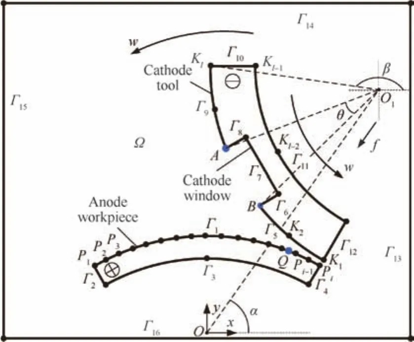
Fig.1 Simplified physical model of the electric potential domain.

whereUrepresents the potential difference between the anode workpiece and the cathode tool.
The current densityjcan be described by Ohm’s law:

3.Simulation process
3.1.Meshing model
The current density distribution based on Eqs.(1)–(5)is calculated using the FEM.As shown in Fig.2,the analytical model is divided into a series of small triangular elements,and the grids of the narrow inter-electrode gap are refined to obtain higher simulation accuracy.To avoid a distorted mesh during simulation,a remesh process for the analytical domain is adopted in each cycle.
3.2.Moving boundary
The simulation of the process is a moving boundary problem becausetheshapeand position oftheelectrodesare time-dependent.The electrodes have much more complex movements than the simple linear motion of a cathode tool in conventional sinking ECM.As shown in Fig.1,two sets of control points,{Pi}and{Kl},are created to construct the boundaries of the anode workpiece and the cathode tool.To reflect the continuously changing anode surface profile with reasonable accuracy during simulation,hundreds of points{Pi}are usually necessary.For the convenience of research on the anode shaping process during CRECM,the anode workpiece is assumed to be motionless,and the cathode tool can be considered to move in rotation and revolution at a constant rotation speed(see Fig.1).

Fig.2 Meshing model in the FEM.
3.2.1.Movement of cathode points
Based on the above assumption,the control pointKl(xk,yk)of thecathodeboundary satisfiesthefollowing kinematic equations:
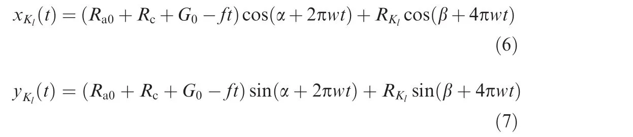
whereRa0is the initial radius of the anode workpiece,mm,Rcis the radius of the cathode tool,mm,G0is the initial minimum inter-electrode gap,mm,fis the cathode feed velocity,mm·min-1,tis the processing time,min,wis the rotation speed,r/min,α is the initial polar angle of the cathode tool,rad,RKlis the polar radius of pointKl,mm,and β is the initial polar angle of pointKl,rad.
3.2.2.Nodal displacement on the anode surface
The changes of the anode shape are determined by the material removal rate on the surface.At each time step,the current density is calculated by solving the Laplace equation using the FEM.Fig.3 shows the initial electric field distribution,where the magenta arrows represent the directions of the current flow,and their lengths represent the intensities of the current density.V,Vx,andVyare the anode shape change rates of control pointPialong normal,x,andydirections.Based on Faraday’s law,the anode shape change rateVcan then be derived from:
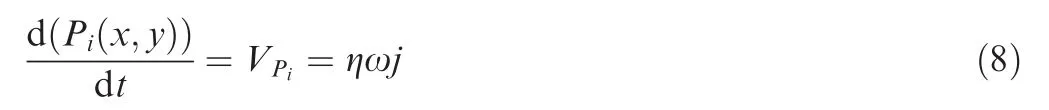
where η represents the current efficiency and ω represents the volume electrochemical equivalent which is determined by the metal composition of the anode workpiece.
3.2.3.Time discretization

Fig.3 Initial electric field distribution within the electrolyte domain.
During the non-stationary anode shaping process,the whole process can be divided intoMcircles,according to the revolu-tions of the electrodes.In each circle,the processing time is discretized intoNshort time periods.The whole processing time is assumed to beT,and the time step Δtcan be calculated as:

Fig.4 shows a schematic diagram of the moving boundaries at different time periods in themth circle.The coordinates of the cathode pointKl(xk,yk)in themth circle andnth time period are:


nth and(n+1)th cycle,whilevxandvyare the values of the removal rate.
3.3.Simulation algorithm
Fig.5 is a flowchart illustrating the simulation algorithm of the anode shaping process.It can be seen that two loops are involved in the simulation algorithm.In the external loop,the count of revolutionsmranges from 1 toM,and in the internal loop,the processing time is divided intoNshort time periods.Thus,there areM×Ncomputational cycles required
where in total.The control points and the electrolyte domain Ω are changed after each computational cycle time.
4.Results and discussion
4.1.Simulation results
To predict the convex shaping process during CRECM,the anode profiles at different processing times are recorded during simulation.The relative parameters are listed in Table 1.
In order to take the current efficiency into account,the currentefficienciesatdifferentcurrentdensitiesofthe nickel-based alloy Inconel 718 in 106 g/L NaNO3solution have been measured.19
4.1.1.Convex structure formation
For a rectangular convex structure,the anode profiles in different cross sections stay the same.As the current densities in the corresponding areas of the cathode window are much lower than those in other sections,the removal amounts are much less,according to Faraday’s law.The convex structure forms gradually with variation of the motion trails.Fig.6 shows the convex profiles at different processing times.It can be seen that the convex profiles are in accord with the motion trails of the edge pointsAandBof the cathode window(see Fig.1).Based on the kinematic Eqs.(6)and(7),the motion trails are determined by the radius of the cathode toolRcand the angle of the cathode window θ.The cathode design problem in CRECM is different from the design of the block tool electrode in conventional ECM.20The convex of different heights can be fabricated by controlling the processing time.When the processing timetextends to 500 min,the height of the convex profile reaches to about 10 mm,indicating that the proposed CRECM process is a feasible technology in fabricating high convex structures on revolving parts.Furthermore,it is found that the corner of the simulated convex profile is sloped and that stray corrosion also exists on the top surface of the convex structure.This can be attributed to expansion of the side gap during rotation of the electrodes,and the non-machined convex structure will inevitably suffer stray current attack.For Inconel 718,stray corrosion may become even more serious due to its high current efficiency at low current density.21

Fig.4 Schematic diagram of the moving boundaries in the mth circle during simulation.

Fig.5 Flowchart of the simulation algorithm.
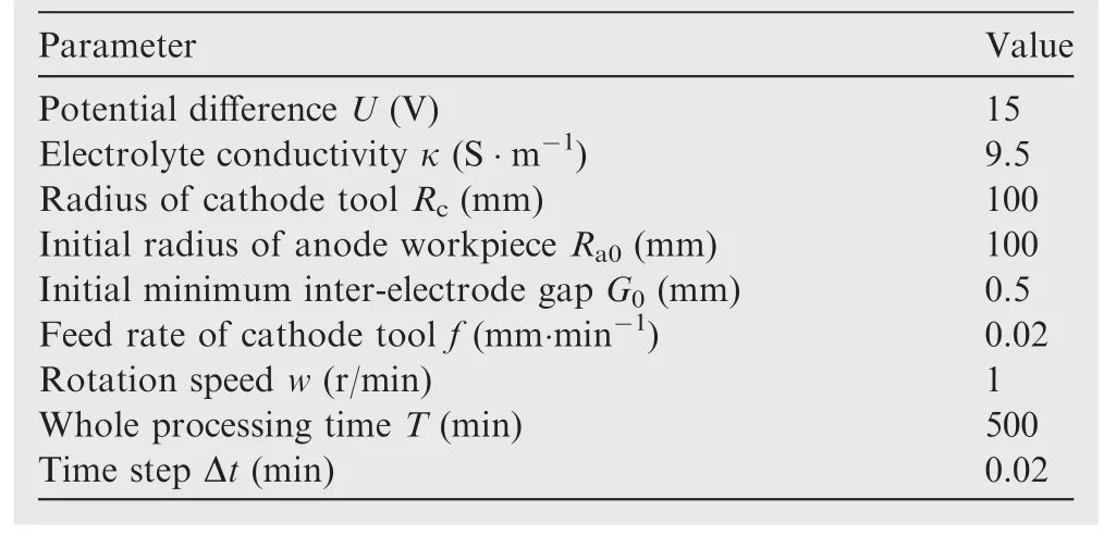
Table 1 Parameters used in the simulation process.

Fig.7 Simulated anode profiles for a circular convex structure at 100 min.
For a complex convex,the anode profiles vary along different cross sections.Here,a cathode tool with a circular window of 20 mm in diameter is chosen for study.Fig.7 shows the simulated convex profiles in different cross sections when the processing time is 100 min.By combining these convex profiles with the surface modeling software Pro/Engineer,the threedimensional shape of the circular convex can be approximately predicted.

Fig.6 Anode profiles of the convex structure with different heights.

Fig.8 Variation of the inter-electrode gap at different processing times.

Fig.9 Current density variation of point Q during the rotating process.
4.1.2.Inter-electrode gap
In contrast to the traditional schemes of machining with linear motion of a tool electrode,the time dependence of the interelectrode gap for cylindrical electrodes needs to be studied.Despite the changes of the convex profiles,the radius of the cylindrical anode surface decreases with the cathode feed.The inter-electrode gaps at different processing times are calculated during the simulation(see Fig.8).It can be seen that the inter-electrode gapGdecreases with increasing processing time,and finally remains at a stable value of 0.16 mm at a time of approximately 90 min.This indicates that the CRECM process can also reach a relative equilibrium state like that of conventionalsinking ECM.According to the simulated balanceable inter-electrode gap,the corrosion depth of the anode workpiece can be controlled by adjusting the feed amount of the cathode tool.
Compared with the actual processing time of 500 min,the numerical simulation process for the convex profiles takes only about 85 min.It is effective and low-cost for the feasible prediction of the CRECM process.
4.1.3.Current density variation
In conventional linear-feed ECM,the spark is likely to happen due to the accumulation of electrolytic products.As the electrodes are rotating during CRECM,the machining gap for pointQon the cylindrical anode surface(see Fig.1)varies continually.This results in a current density variation of pointQduring the rotating process.The current densities of pointQat different rotation angles are obtained numerically.As shown in Fig.9,a cyclic variation of the current density of pointQis found.The change periodT1depends on the rotation speedw.During each cycle,the machining of pointQoccupies only a small portion of the processing time.This kind of pulse processing can be beneficial for the timely removal of electrolytic products and the improvement of machining quality.
4.2.Experimental verification
Previous simulation results have shown that the CRECM process is feasible in the fabrication of convex structures on revolv-ing parts.An experimental system is developed and an experiment is conducted to verify the validity of the simulation.

Fig.10 Schematic diagram of the experimental system.
As shown in Fig.10,the experimental set-up consists of an electrode rotation and movement system,an electrolyte circulation system,a power supply system,and a current direction system.The cylindrical anode workpiece and the cathode tool are mounted on two shafts,which can rotate relative to each other at the same rotation speedw.Moreover,the cathode tool can move alongXdirection and the anode workpiece can move alongZdirection during the experiment.To apply a potential difference to the rotating electrodes,conducting rings are installed on the shafts.The machining current is acquired using a Hall current sensor and recorded using a real-time acquisition system.
In this paper,a rectangular convex and a circular convex are successfully fabricated at the same time,and the processing time lasts for 100 min.The rectangular convex structure is divided along its cross section,and the cross-sectional profile is shown in Fig.11(a).To compare the top face contour of the circular convex structure,the points that are on the same arc radius are chosen from the simulated anode profile in each cross section(see Fig.8).By connecting these points using splines,the simulated top face contour of the circular convex structure on a certain arc radius can be plotted(see Fig.11(b)).From the comparison,it can be observed that both the cross-sectional profile of the rectangular convex structure and the top face contour of the circular convex structure display good agreements with the simulated results.
The current signal acquired by the Hall current sensor during the experiment is shown in Fig.12.The fluctuations of the measured current are mainly caused by errors of the machine tool and the cylindricity of the electrodes.It can be seen that the current increases with increasing processing time.The increasing current can be attributed to the decrease of the inter-electrode gap.As the process continues,the current value tends to remain constant,which indicates that the interelectrode gap reaches a relative equilibrium state.This is in accord with the variation of the simulated inter-electrode gap(see Fig.8).

Fig.11 Comparison of simulation and experimental results.
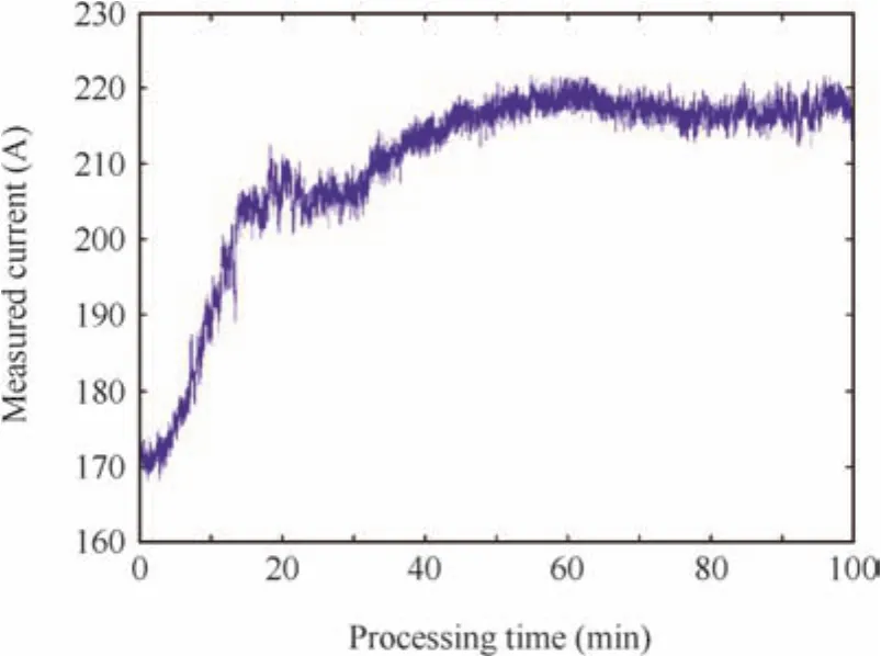
Fig.12 Current signal acquisition during the experiment.
5.Conclusions
This paper has presented a convex shaping process on revolving parts using a revolving cathode tool during CRECM.The conclusions can be summarized as follows:
(1)The finite element method has been used for the feasibility prediction on the convex shaping process.A mathematical model and a simulation algorithm have been extensively described.
(2)The simulated anode profiles at different processing times have shown that the proposed ECM process is feasible to fabricate convex structures with different heights.The variation of the inter-electrode gap indicates that the CRECM process can also reach a relative equilibrium state like that of conventional sinking ECM.Besides,the current density variation of a point on the cylindrical anode surface has presented a pulse effect during CRECM.
(3)A rectangular convex and a circular convex have been successfully fabricated at the same time.The experimental results indicate relatively good agreement with the simulation results.The proposed simulation process is valid for convex shaping prediction and feasibility studies as well.
Acknowledgement
This work was supported by the Program for New Century Excellent Talents in University of China(NCET-10-0074).
1.MountAR,EleyKL,CliftonD.Theoreticalanalysisof chronoamperometric transients in electrochemical machining and characterization of titanium 6/4 and inconel 718 alloys.J Appl Electrochem2000;30(4):447–55.
2.Qu NS,Fang XL,Li W,Zeng YB,Zhu D.Wire electrochemical machining with axial electrolyte flushing for titanium alloy.Chin J Aeronaut2013;26(1):224–9.
3.Rajurkar KP,Zhu D,McGeough JA,Kozak J,DeSilva A.New developments in electro-chemical machining.CIRP Ann1999;42:231–4.
4.Venkata Rao R,Kalyankar VD.Optimization of modern machining processes using advanced optimization techniques:a review.Int J Adv Manuf Technol2014;73(5–8):1159–88.
5.Xu ZY,Xu Q,Zhu D,Gong T.A high efficiency electrochemical machining method ofblisk channels.CIRPAnn2013;62(1):187–90.
6.Mahdavinejad R,Hatami M.On the application of electrochemical machining for inner surface polishing of gun barrel chamber.J Mater Process Technol2008;202(1–3):307–15.
7.Qu NS,Chen XL,Li HS,Zeng YB.Electrochemical micromachining of micro-dimple arrays on cylindrical inner surfaces using a dry-film photoresist.Chin J Aeronaut2014;27(4):1030–6.
8.Dhobe SD,Doloi B,Bhattacharyya B.Surface characteristics of ECMed titanium work samples for biomedical applications.Int J Adv Manuf Technol2011;55(1–4):177–88.
9.Sheng W,Xu B.Technological test of electrolytic machining of aero-engine casing.Electromach Mould2010;2:52–9 Chinese.
10.Zhu H,Zhu ZW,Wang HR,Zhu D.Simulation and experiment research of rotate-print ECM.Electromach Mould2012;1:29–32 Chinese.
11.Kozak J,Budzynski AF,Domanowski P.Computer simulation electrochemical shaping(ECM-CNC)using a universal tool electrode.J Mater Process Technol1998;76(1–3):161–4.
12.Domanowski P,Kozak J.Inverse problem of shaping by electrochemical generating machining.J Mater Process Technol2001;109(3):347–53.
13.Pattavanitch J,Hinduja S,Atkinson J.Modelling of the electrochemical machining process by the boundary element method.CIRP Ann2010;59(1):243–6.
14.Purcar M,Bortel L,Bossche BV,Deconinck J.3D electrochemical machiningcomputersimulations.JMaterProcessTechnol2004;149(1–3):472–8.
15.Kim J,Kim D,Choi H.An immersed-boundary finite-volume method for simulations of flow in complex geometries.J Comput Phys2001;171:132–50.
16.Wang L,Wang QD,Hao XQ,Ding YC,Lu BH.Finite element simulation and experimental study on the through-mask electrochemical micromachining(EMM)process.Int J Adv Manuf Technol2010;51(1–4):155–62.
17.Wang MH,Zhu D.Simulation of fabrication for gas turbine blade turbulated cooling hole in ECM based on FEM.J Mater Process Technol2009;209(4):1747–51.
18.Sun CH,Zhu D,Li ZY,Wang L.Application of FEM to tool design for electrochemical machining freedom surface.Finite Elem Anal Des2006;43:168–72.
19.Wang DY,Zhu ZW,Wang NF,Zhu D,Wang HR.Investigation of the electrochemical dissolution behavior of Inconel 718 and 304 stainlesssteelatlow currentdensityin NaNO3solution.Electrochim Acta2015;156:301–7.
20.Zhu ZW,Wang DY,Bao J,Wang NF,Zhu D.Cathode design and experimentalstudyon therotate-printelectrochemical machining of revolving parts.Int J Adv Manuf Technol2015;80(9):1957–63.
21.Wang DY,Zhu ZW,Bao J,Zhu D.Reduction of stray corrosion by using iron coating in NaNO3solution during electrochemical machining.Int J Adv Manuf Technol2015;76(5–8):1365–70.
10 April 2015;revised 1 June 2015;accepted 6 June 2015
Available online 1 September 2015
ⓒ2015 The Authors.Production and hosting by Elsevier Ltd.on behalf of CSAA&BUAA.This is an open access article under the CC BY-NC-ND license(http://creativecommons.org/licenses/by-nc-nd/4.0/).
*Corresponding author.Tel.:+86 25 84896605.
E-mail address:zhuzw@nuaa.edu.cn(Z.Zhu).
Peer review under responsibility of Editorial Committee of CJA.
Zhu Zengweiis a professor and Ph.D.advisor in the College of Mechanical and Electrical Engineering at Nanjing University of Aeronautics and Astronautics in China.He received his Ph.D.degree from the same university.His current research interests are electrochemical machining and electroforming.
杂志排行

CHINESE JOURNAL OF AERONAUTICS的其它文章
- Hypersonic starting flow at high angle of attack
- Advances and trends in plastic forming technologies for welded tubes
- Instability and sensitivity analysis of flows using OpenFOAM®
- Numerical simulations of high enthalpy flows around entry bodies
- Modeling and simulation of a time-varying inertia aircraft in aerial refueling
- Experimental investigations for parametric effects of dual synthetic jets on delaying stall of a thick airfoil