Experimental investigations for parametric effects of dual synthetic jets on delaying stall of a thick airfoil
2016-11-23ZhoGuoqingZhoQijunGuYunsongChenXi
Zho Guoqing,Zho Qijun,*,Gu Yunsong,Chen Xi
aNational Key Laboratory of Science and Technology on Rotorcraft Aeromechanics,Nanjing University of Aeronautics and Astronautics,Nanjing 210016,China
bCollege of Aerospace Engineering,Nanjing University of Aeronautics and Astronautics,Nanjing 210016,China
Experimental investigations for parametric effects of dual synthetic jets on delaying stall of a thick airfoil
Zhao Guoqinga,Zhao Qijuna,*,Gu Yunsongb,Chen Xia
aNational Key Laboratory of Science and Technology on Rotorcraft Aeromechanics,Nanjing University of Aeronautics and Astronautics,Nanjing 210016,China
bCollege of Aerospace Engineering,Nanjing University of Aeronautics and Astronautics,Nanjing 210016,China
Active flow control;Airfoil;Dual synthetic jet arrays;Flow separation;Stall
A promising strategy of synthetic jet arrays(SJA)control for NACA0021 airfoil in preventing flow separation and delaying stall is investigated.Through aerodynamic forces,flowfield and velocity profiles measurements,it indicates that the synthetic jet(SJ)could enlarge the mixing of the shear layer and then enhance the stability of boundary layer,resulting in scope reduction of the flow separation zone.Furthermore,the control effects of dual jet arrays positioned at 15%c(Actuator 1)and 40%c(Actuator 2)respectively are systematically investigated with different jet parameters,such as two typical relative phase angles and various incline angles of the jet.The jet closer to the leading edge of airfoil is more advantageous in delaying the stall of airfoil,and overall,the flow control performances of jet arrays are better than those of single actuator.At the angle of attack(AoA)just approaching and larger than the stall AoA,jet array with 180°phase difference could increase the lift coefficient more significantly and prevent flow separation.When momentum coefficient of the jet arrays is small,a larger jet angle of Actuator 2 is more effective in improving the maximum lift coefficient of airfoil.With a larger momentum coefficient of jet array,a smaller jet angle of Actuator 2 is more effective.
1.Introduction
The flow separation and stall lead to lift decrease of airfoil,and thus,limit flight speed envelope and improvement of aerodynamic performance of aircraft.1Active flow control(AFC)has been one of the most promising methods for improving aerodynamic characteristics of airfoil,and further expanding operating envelope of aircraft.2–5As a novel AFC method,synthetic jet has been confirmed to be an efficient technologyto control flow separation and stall of airfoil at different status.6–9Though synthetic jet introduces zero net-mass-flux into fluid flows,it provides effective unsteady momentum addition in the form of vortex pairs or vortex rings without the bulk and cost of the steady sources.10
In order to disclosure control mechanism of synthetic jet on delaying flow separation and stall of airfoil,Seifert et al.conducted active control experiments on NACA0015 airfoil,and the capability of synthetic jet on delaying stall of airfoil was verified.11Several experimental results have indicated that synthetic jet localized near the location where flow separation forms can significantly enhance aerodynamic characteristics of airfoil,includingincrementofmaximumliftandstallangle.12–17
According to the investigations about control effects of jet location on airfoil performance,jet arrays containing two or more actuators placed at different chord positions were designed to further delay stall of airfoil.Hassan carried out numerically investigation on stall control of airfoil via jet array with two actuators,18and the simulated results preliminarily indicated that jet array helps to further improve aerodynamic characteristics of airfoil.Regrettably,the two jet actuators with one pulsed suction jet and the other pulsed blowing jet turned on alternately;as a result,the interactions of the two jets were not taken into account.Additionally,experimental investigations on airfoil stall and flow separation control using synthetic jet arrays were carried out to further analyze the characteristics of jet arrays.19,20The experimental results preliminarily showed that the synthetic jet arrays(SJA)had potential in delaying flow separation and improving aerodynamic performance of airfoil than single jet.However,the investigations of these references focused on the control effects of jet arrays with fixed few parameters and the aerodynamic interaction between jet actuators was ignored.At the same time,there is still a lack of research on the influence of control effects due to varied parameters of jet array.
In order to better understand parametric effects of jet array,Lee et al.experimentally investigated separation control for an inclined flat plate by jet arrays with varied parameters.21The results indicated that the location and phase of a synthetic jet array may be essential for flow separation control effects.Unfortunately,the investigations on airfoil stall control via jet array were not carried out,so Lee pointed out that control effects of dual jet array on airfoil should be further investigated to understand the separation control mechanism of jet arrays.
Until now,the control mechanisms of the interaction between different actuators of jet array are not clear yet,there is still a lack of parametric analyses of jet array control on airfoil stall and flow separation in particular.22,23
In this paper,to further explore the physical understanding of flow control effects on airfoil via jet arrays,comprehensive experimental investigations have been conducted on synthetic jet array control of NACA0021 airfoil.The tests include aerodynamic force and flowfield measurements in wind tunnel.Furthermore,in emphasis,parametric analyses of jet arrays on stall and flow separation control effects are carried out,especially two typical jet phase difference and a series of relative jet angles between different jet actuators,and some valuable conclusions are obtained,which help to better understand the regularity of jet array control on stall of airfoil and provide foundations for further parametric optimization design of jet array.
2.Experiment platform and procedure
2.1.Airfoil model and synthetic jet array
In the present experiments,the 1-inch full range speaker units are designed as jet actuators,and three typical jet directions are achieved using different covers with varied jet angles,see Fig.1.The actuators are placed at 15%c(Actuator 1,A1)and 40%c(Actuator 2,A2)of airfoil respectively.
Considering the size of actuators,and the installation of the actuatorarraysin airfoilmodel,NACA0021airfoilis employed in the experiment.The parameters of experimental airfoil(wing)model and jet actuators are shown in Table 1.
Fig.2 shows that the root mean square(RMS)velocity varies with the excitation frequencyfat the centerline of jet orifice of an isolated actuator according to different excitation voltages.As shown in the figure,the RMS velocity of jet increases with a larger excitation voltageUjet,and there is a peak RMS velocity when the excitation frequency is about 200 Hz(which is adopted in the whole test).In addition,the differences among jet velocity with different jet angles θjetare very small;for unity,the variation of the jet velocity with the excitation voltage is taken the average of the three cases.
2.2.Measuring equipment

Fig.1 Jet actuators and their installation in airfoil(wing)model.

Table 1 Parameters of airfoil model and jet actuators.
The tests of synthetic jet array control for large flow separation of airfoil in stall are conducted in low-speed return flow windtunnel(with a circular experimental section)of Nanjing University of Aeronautics and Astronautics.The experiments include aerodynamic force measurements of airfoil,flow velocity measurements over airfoil by particle image velocimetry(PIV)technology and evaluation of velocity profiles in boundary layer.System for measurement of aerodynamic force includes six-component balance,regulated power supply,signal amplifier,16 bit data acquisition card,computer and special testing software.The PIV system contains double pulse laser source,optical element,CCD camera,synchronizing device,insight 3G processing programs and traditional solid particles device.The main parameters of PIV system are given in Table 2.Fig.3 illustrates the model experimental equipment and PIV measuring scene.The diameter of the particle is about 5 μm,and error of PIV measurement is about 2%.

Fig.2 RMS velocity of jet actuator with respect to relative excitation frequency and voltage.
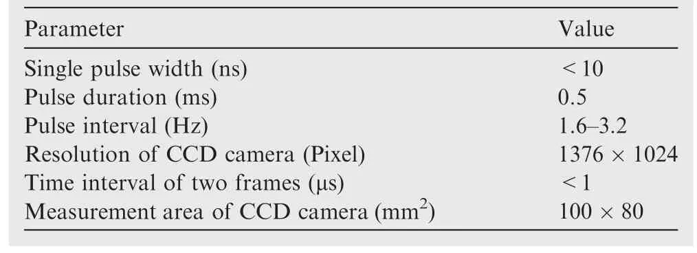
Table 2 Main parameters of PIV system.
2.3.Experimental content and method
In order to analyze the control effects of the synthetic jet array on flow separation of airfoil,comprehensive experiments have been conducted at free stream velocities ranging from 5 to 25 m/s,and the maximum Reynolds number based on the chord of airfoil is about 3.0×10⁵.The turbulence intensity of the wind tunnel is about 1.2%measured by the hot wire anemometer.Considering the similarity of turbulence intensity and Reynolds number,24the free-stream turbulence intensity is significant on both the airfoil boundary layer and the separated shear layer,and large turbulence intensity could enlarge the maximum lift coefficient and stall angle of attack(AoA)of airfoil.To measure the stall angle of airfoil under jet array control,the range of AoA is set from-6°to 30°with excitation voltage of jet actuator ranging from 0 to 5 V(0 V is the baseline case without jet control).
Fig.4 shows the schematics of the measurements of model aerodynamic force and velocity-field by the PIV method.In order to improve the accuracy of the CCD camera in capturing detail information of local flowfield over airfoil,three valid zones of PIV measurement are distributed to comprehensively cover the suction surface of airfoil.Distributions of PIV measurement zones are also shown in Fig.4.

Fig.3 Experimental equipment and PIV measuring scene.
3.Results and discussion
3.1.Synthetic jet array control effects over airfoil stall
To verify the control effects of synthetic jet on lift coefficientCLand stall of airfoil,the jet control tests are carried out with the actuator at 15%cof airfoil(A1)turned on.Fig.5 shows a comparison of the variation of lift coefficients under different excitation voltagesUjetwith 30°jet angle and free stream velocity 15 m/s.As shown in the figure,there are abrupt discontinuities when angle of attack exceeds the stall angle with maximum lift.With synthetic jet array control,the maximum lift coefficient and stall angle of airfoil increase signif icantly.Additionally,as the excitation voltage increases,the jet has better control effects on improving the aerodynamic characteristics of airfoil.There is about 15.36%increment of maximum lift coefficient of airfoil and about 4°angle of attack α delay of airfoil stall at 5 V voltage compared to the baseline case.
Fig.6 illustrates the streamlines over airfoil at 17°AoA with different excitation voltages measured by the PIV tests.At this AoA before stall,the velocity vector of flow is deflected to the surface of airfoil by jet array control.Additionally,as the excitation voltage(momentum coef ficient)increases,the flow is more attached over the suction surface of airfoil,resulting in the increment of lift coef ficient of airfoil.

Fig.4 Schematic of experiment and distributions of PIV measurement zones.

Fig.5 Lift coefficient of airfoil under synthetic jet array control.
As can be seen from the contour of velocityVshown in Fig.7,when airfoil stall occurs at α =21°,synthetic jet array can effectively make the flow attach to the surface of airfoil,and then decrease the large flow separation starting from the leading edge of airfoil.The in fluences of the periodic synthetic jet(SJ)are that jet array can directly introduce flow energy into the boundary layer of separated flow with low energy over the airfoil,and the blow and suction motion of jet can enlarge the mixing of flow between the outer and inner layer,which lead to the stability of the boundary layer.
The effects of the momentum adding into the cross- flow of airfoils by synthetic jet have two different ways to affect the flow characteristics of airfoil.18On one hand,the additional momentum parallel to the stream-wise flow can bring directly benefit by energizing the boundary layer flow.On the other hand,the component of the jet normal to the surface of airfoil can introduce high-momentum outer fluid into the lowmomentum inner boundary layer flow in recirculation regions,resulting in the boundary layer stability.

Fig.6 Streamlines over upper surface of airfoil at α =17°.
Fig.8 shows the comparisons of streamlines of Zone II and Zone III over airfoil at α =21°with different excitation voltage.Obviously,the flow of the baseline case is completely separated near the trailing edge of airfoil and Zone III is a recirculation zone.With the control of periodic synthetic jet,the reverse flow turns to be reattached to the surface of airfoil,thus the stall of airfoil is signi ficantly postponed.Furthermore,flow velocity can be better regained with a larger control voltage.
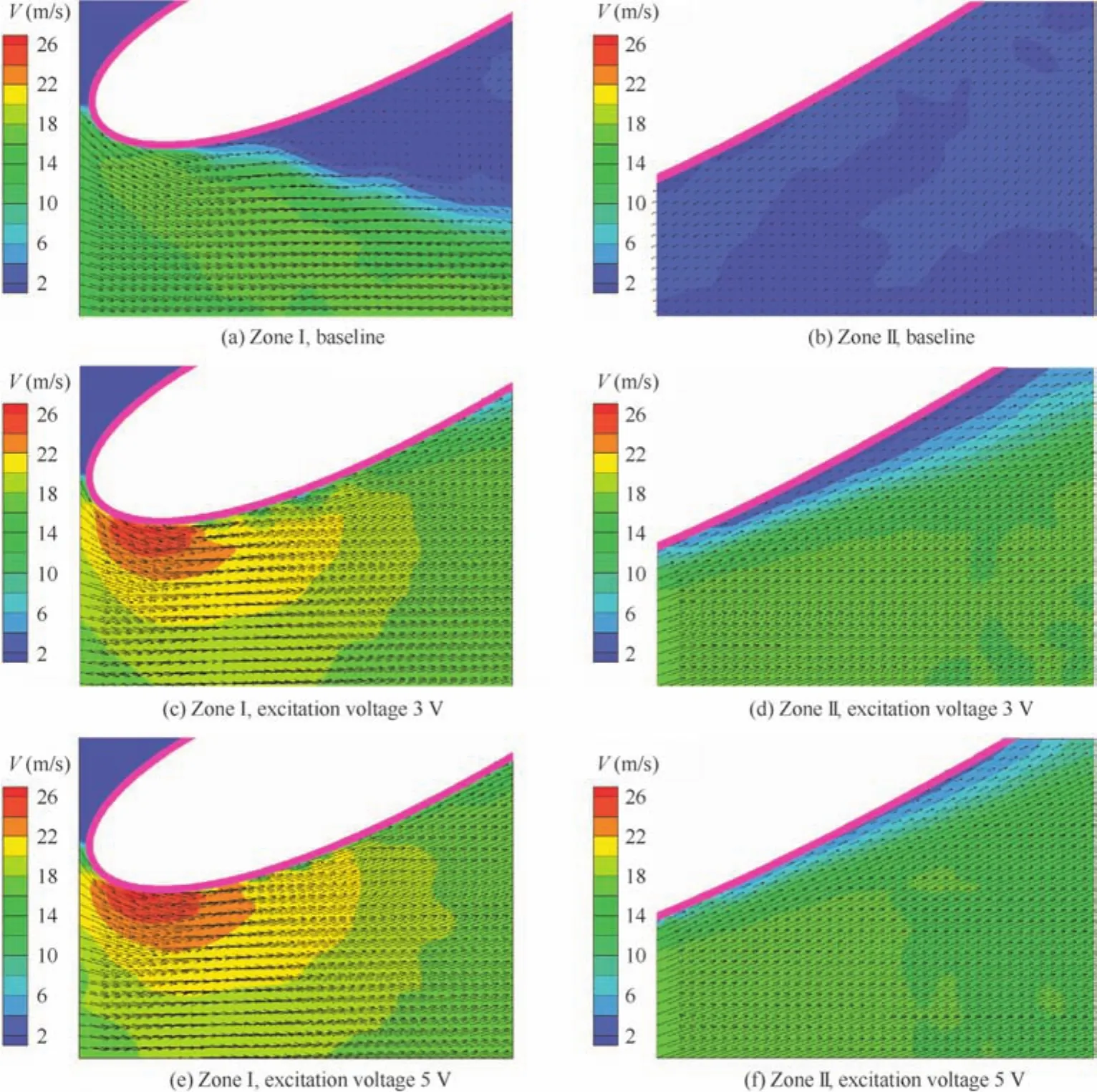
Fig.7 Velocity contours and streamlines over airfoil at α=21°.
When the angle of attack is much larger than the stall angle of airfoil,the control effect of synthetic jet may decrease significantly(see Fig.9).

Fig.8 Comparisons of streamlines over airfoil with and without SJ control with different excitation voltage at α =21°.
In order to investigate the control effects of synthetic jet on boundary layer of a post-stalled airfoil(AoA larger than 25°),the velocity profiles(η denotes the normal distance away from the airfoil)of boundary layer at 20%cand 40%care measured by boundary layer probe when AoA of airfoil is 22°.Fig.10 shows the velocity profile with different excitation voltages and the jet angle is 90°.It is necessary to point out that there is no positive component velocity along the free inflow at 40%cof airfoil due to large recirculation phenomenon.δ1and δ2are boundary layer displacement and momentum thickness respectively,and δ1/δ2is the form factor of velocity profile.As can be seen,without jet control,the positions of 20%cand 40%care in large recirculation zone,especially at 40%c.When jet control is turned on,the boundary layer exhibits typical turbulent characteristics,and the recirculation zone is effectively inhibited,resulting in the reattachment of the flow over the airfoil.With the RMS velocity increases,the interaction between synthetic jet and separated flow becomes more intense,and the mixing influence of the jet is more effective,which can better overcome the adverse pressure gradient and further lead to the reattachment of the flow over the airfoil.
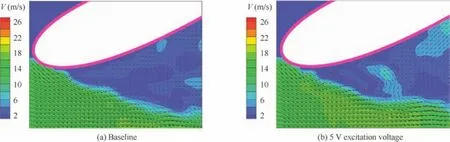
Fig.9 Velocity contours and velocity vector over airfoil at α =25°.
3.2.Effects of synthetic jet location
The different control effects of the jet on lift coefficient of airfoil due to the location of the actuator orifice are investigated by turning on the two actuators at 15%cand 40%cof airfoil respectively.The comparisons of the control effects of synthetic jet on flow separation by the two actuators respectively at different free stream speedsV∞and under different jet control conditions are illustrated in Fig.11.As can be seen,the ΔCLis relative small at AoAs of airfoil before stall.Otherwise,when stall occurs,the lift coefficient of clear airfoil deceases dramatically,and synthetic jet can maintain the lift of airfoil in stall at a high level,resulting in large ΔCLof airfoil in the post stall region.When AoA of airfoil is large enough,the control effects of jet reduce,leading to decreases of ΔCLof airfoil.
It can be seen immediately that A1 is generally more efficient on delaying stall of airfoil than A2.The main reason is that the large flow separation leads to a shear layer near the leading edge of airfoil when stall occurs,andA1 is closer to the unstable shear layer,and thus it can directly inject momentum(energy)into the boundary flow with low momentum(energy).10At the same time,the periodic blowing and suction motions of synthetic jet can enhance the mixing of the flow by introducing high momentum outer flow into the near-wall boundary layer,and thus it can prevent the formation of the shear layer and further decrease flow separation over airfoil,resulting in the improvements of airfoil aerodynamic characteristics.
In addition,the momentum excitation voltage and jet angle play important roles in the control effects of airfoil stall.As excitation voltage increases,the maximum lift coefficient and the stall AoA of airfoil show significant increments also.Considering the influence of jet angle coupling with the free stream speed and the RMS velocity of synthetic jet,the momentum coefficient of jet is introduced and is defined as


Fig.10 Test results of boundary layer velocity profiles.
wherehis the width of the actuator orifice,cthe chord length of airfoil,Vjetthe RMS velocity of the jet.At a certain excitation voltage of jet,with the increase of the free stream velocity,the momentum coefficient decreases obviously,whileCμincreases when the RMS velocity increases with a fixed inflow.
For single A1,when momentum coefficient is large enough,a nearly tangential jet can dramatically enhance the control effects(increment of stall AoA of airfoil)as shown in Fig.11(a)and(b).On the other hand,as momentum coefficient decreases,the differences of control effects due to different jet angles become small,and even the jet with large jet angle 60°is more effective than the jet with jet angle 30°,as shown in Fig.11(d).
Additionally,for single A2,when jet momentum coefficient is small,for example in Fig.11(c),jet control of A2 leads to the decrease of lift coefficient near the airfoil stall AoA,and with the increase of jet angle,the decrease of lift coef ficient intensifies.Differently,as momentum coef ficient of A2 increases,jet control of A2 leads to the increase of lift coef ficient near the stall AoA of airfoil.Furthermore,jet angle of A2 shows a similar role to A1.For example,when jet momentum coefficient is large,a 30°jet is more effective in increasing the lift coefficient of airfoil(see Fig.11(b)).At the same time,a jet with 30°jet angle is more effective when momentum coefficient of A2 is relatively small(see Fig.11(a)).The results are somewhat with good agreement with the numerical investigations of Ref.25.

Fig.11 Comparisons of control effects for different actuators on lift coefficient of airfoil.

Fig.12 Comparisons of lift coefficients with varied jet momentum coefficients at different AoAs.
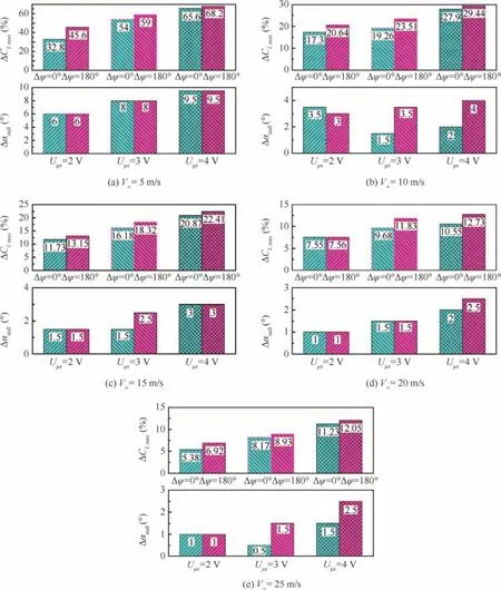
Fig.13 Effects of phase differences of jet array on airfoil stall control.
3.3.Effects of relative phase angles
In order to investigate the role of relative phase angles in synthetic jet array control on airfoil stall,and considering the difficulties in setting the relative phase difference of jet array,two typical and easy-achieving phase angle differences(0°and 180°)between A1 and A2 are employed in the present experiments.
Fig.12 shows a comparison of lift coefficient varying with momentum coefficient under different synthetic jet array controls and with different AoAs of airfoils.The inflow velocity is 15–30 m/s,and the jet angles of the two actuators are both 30°.
Under jet arrays control,in general,single A2 is more effective than A1 in increasing the lift coefficient of airfoil under all the three inflow conditions with small AoA of airfoil(see Fig.12(a)).It is because that little flow separation occurs near A2 at the AoA of airfoil without the onset of stall,and jet induced by A2 could inject momentum to the separated flow over airfoil more directly.As the AoA increases,the flow separation point moves towards the leading edge of airfoil,then,A1 shows its superiority to the control of leading-edge flow separation,resulting in enhancement of airfoil aerodynamic characteristics.
Fig.12 shows that jet arrays have better performance in increasing lift coefficient of airfoil than single actuators from the overall perspective.Besides,at lower AoAs as shown in Fig.12(a),the airfoil lift coefficient under control of jet array with the same phase angle is almost larger than that of jet array with 180°phase difference Δψ as a whole.Differently,with AoA just being approaching and larger than stall AoA,jet array with 180°phase difference is the most significant method to increase lift coefficient of airfoil among the four control modes(two single actuator control;jet arrays with two different relative phase angles).
To get more details of different control effects of the two typical jet arrays at 0°and 180°relative phase angles between A1 and A2,the comparisons of the increments of stall AoA Δαstalland maximum lift coefficients ΔCLmaxof airfoil under different conditions(with free stream velocities ranging from 5 to 25 m/s,and the excitation voltage of both jet actuators ranging from 2 to 4 V)are illustrated in Fig.13.
As can be seen from the figure,both of the jet arrays can remarkably enhance the flow control effects on a stalled airfoil with large momentum coefficient(at 5 m/s free stream velocity),and the jet array with 180°relative phase angle has better performance in increasing the maximum lift coefficient of airfoil compared with the other case.At a certain free stream velocity,the increase of excitation voltage results in a larger momentum coefficient of jet actuator and it leads to better control effects on both delaying stall and enlarging the maximum lift coefficient of airfoil.The increase of free stream velocity leads to a decrease of momentum coefficient of synthetic jet,which significantly reduces the beneficial control effects.In any cases,the maximum airfoil lift coefficients under the control of jet array with 180°phase angle difference are larger than that with the same phase angle.In general,the delay of stall AoAs of airfoil has the same trend.
Furthermore,as the free stream velocity increases,the increment percentage of lift coefficient decreases.For example,when the excitation voltage of jet array with 180°relative phase angle is 4 V,there are 68.2%and 9.5°increments of lift coefficient and stall AoA of airfoil respectively at the 5 m/s inflow condition,while the increment of lift coefficient and stall AoA of airfoil reduce to 12.05%and 2.5°at the 25 m/s inflow condition respectively.
Figs.14 and 15 show the maximum lift coefficientsCLmaxand stall AoAs αstallof airfoil versus momentum coefficient under control of different jet arrays respectively.The jet angles of the two jet actuators are both 30°.The maximum lift coefficient of a jet array controlled airfoil increases due to the increment of the momentum coef ficient of jet actuator and the stall AoA shows the same trend from an overall perspective.The relative phase angle between the two actuators of jet array is essential for lift control of a stalled airfoil,and the jet arrays with 180°phase angle difference are more effective.Additionally,the stall AoA of airfoil is less affected by the phase difference under jet array control with different momentum coefficients as a whole.
3.4.Effects of jet array at different jet angles
Since jet angle plays an important role of synthetic jet control in stall and flow separation of airfoil,the different contributions of jet arrays with varied relative jet angles are investigated by changing the cover of jet actuators.Combinations of jet arrays with different relative jet angles are shown in Table 3.
Fig.16 shows the increments of stall AoA and maximum lift coefficient with different jet array combinations.The control effects due to relative jet angles are very complicated as shown in the figure.Overall,when jet angle of A1 is 30°,the control effects on airfoil stall of dual jet actuators are better than those of a single actuator.Jet angle of A2 plays an important role in improving aerodynamic characteristics of airfoil.For example,when momentum coefficient of the jet is small(shown in Fig.16(c)),a larger jet angle(almost 90°)of A2 is more effective on improving the maximum lift coefficient of airfoil.With a larger momentum coefficient of jet,a smaller jet angle of A2(60°in Fig.16(b)and(d)and 30°in Fig.16(a))is more effective.The varied trend of stall AoA increment is similar to that of maximum lift coefficient when jet angle of A1 is 30°.
When jet angle of A1 is 60°,the jet arrays control effects are almost the same as those of A1 with jet angle of 30°.There are exceptions as shown in the test results,for example,the control effects of jet arrays of No.6 and No.8 are somewhat less than those of single jet A1.

Fig.14 Effects of phase differences of jet array on maximum lift coefficient of airfoil.

Fig.15 Effects of phase differences of jet array on stall angle of attack for airfoil.

Table 3 Number of jet array combinations at different relative jet angles.
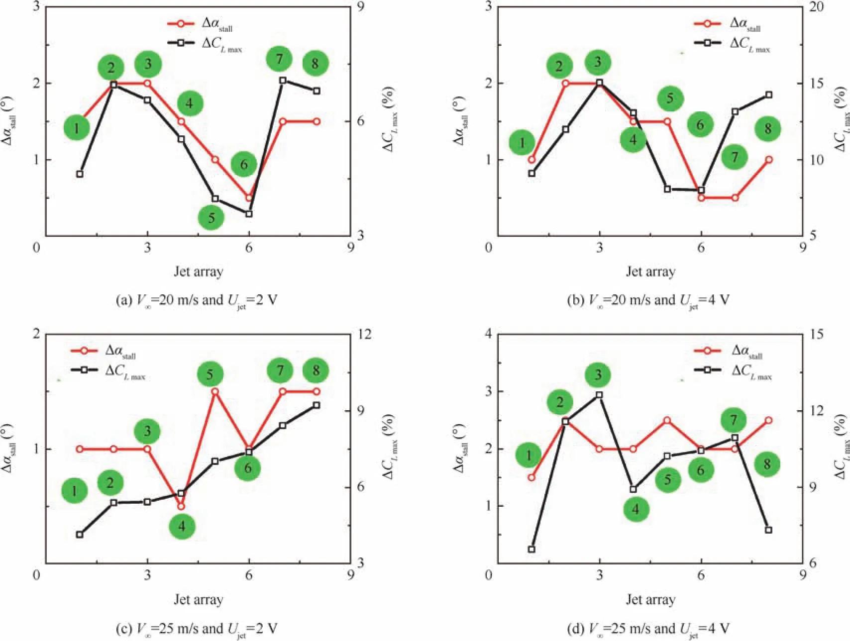
Fig.16 Increment of stall AoA and maximum lift coefficients due to different combinations of jet array.
Figs.17 and 18 show the maximum lift coefficient and stall AoA of airfoil under different jet arrays control with various relative jet angles.
As can be seen in Fig.17(a),a larger momentum coefficient of jet arrays is more effective on enhancing the lift characteristics of airfoil.Additionally,jet arrays with jet angle of A1 being 30°have the capability to increase the maximum coeff icient of airfoil more effectively than those with single jet actuator.Furthermore,the best jet angle of A2 on increasing the maximum lift coefficient of airfoil varies with the momentum coefficient of jet arrays:at a smallCμ,A2 with 30°incline angle is most effective,while asCμincreases,a larger jet angle of A2 is required to maximize lift coefficient of airfoil(60°whenCμ=0.00512 and 90°whenCμ=0.008).The airfoil stall AoA shows almost the same trend as the maximum lift coeff icient of airfoil.
For the cases when jet angle of A1 is 60°which is different from jet arrays Nos.1–4,jet arrays Nos.5–8 have different performances in delaying stall of airfoil.In some cases,the control effects of jet arrays on lift coefficient of airfoil are less effective than those of single actuator.The more effective jet array(with different jet angles of A2)on the lift control of airfoil varies with the different momentum coefficients of jet array.Different from control effects on lift coefficient of airfoil,the stall angle of attack shows an incremental trend using jet arrays control rather than using a single jet.
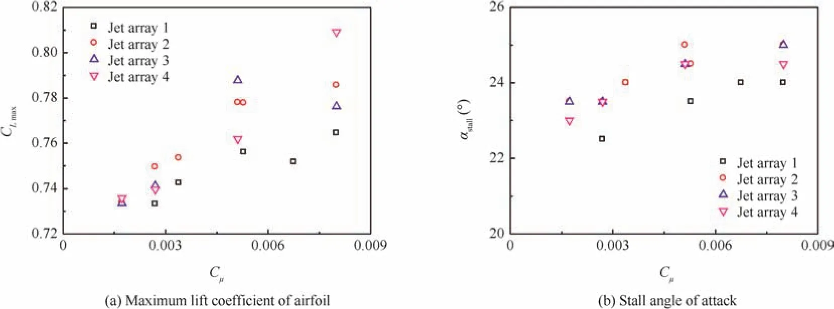
Fig.17 Effects of relative jet angle of jet array on stall control of airfoil for jet array Nos.1–4.
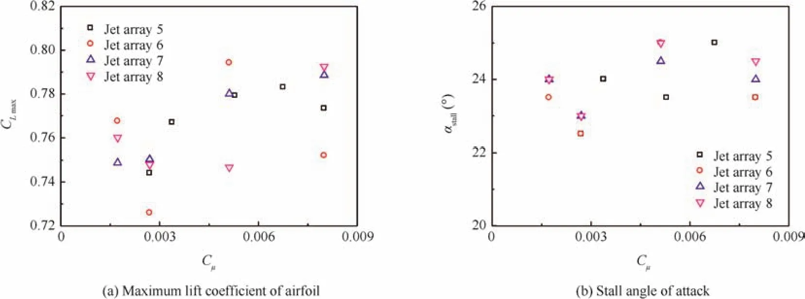
Fig.18 Effects of relative jet angle of jet array on stall control of airfoil for jet array Nos.5–8.
4.Conclusions
Comprehensive tests have been conducted to investigate the control effects of synthetic jet arrays on preventing flow separation and postponing stall of airfoil.As an emphasis,jet arrays with two typical phase angle differences and a series of relative jet angles are designed to analyze their control effects on increments of stall AoA and maximum lift coeff icient of airfoil.Based on the presented experimental data,some meaningful conclusions are obtained as follows.
(1)The systematic wind tunnel tests are effective in analyzing the stall control effects of airfoil by employing dual synthetic jet arrays,and the capabilities of jet arrays in delaying flow separation and delaying stall of airfoil are well verified.
(2)Jet actuator near the leading edge of airfoil can dramatically increase the maximum lift coefficient and stall AoA of airfoil.In addition,the most effective jet angle varies according to the momentum coefficient of jet:a nearly tangential jet is required with a large momentum coefficient,while a large jet angle is more effective with a small momentum coefficient.
(3)Overall,jet arrays have better performances than single actuators,and the lift coefficient of airfoil under jet arrays control with the same phase angle is almost larger than that of jet array with 180°relative phase angle when AoA of airfoil is small.With angle of attack just being approaching and larger than stall AoA,jet array with 180°phase angle difference is more effective than jet array with same phase angle on increasing lift coeff icient of airfoil.
(4)Jet angle of A2 plays an important role in improving stall characteristics of airfoil.When momentum coeff icient of jet array is small,a larger jet angle of A2 is more effective in improving the maximum lift coefficient of airfoil.With a larger momentum coefficient of jet,a smaller jet angle of A2 is more effective.
Acknowledgment
This research has benefited greatly from the support of the NationalNaturalScience Foundation ofChina (No.11272150).
1.Han ZH,Zhang KS,Song WP,Qiao ZD.Optimization of active flow control over an airfoil using a surrogate-management framework.J Aircr2010;47(2):603–12.
2.Kalogirou S,Lloyd S,Ward J.Modeling,optimization and performance evaluation of a parabolic trough solar collector steam generation system.Sol Energy1997;60(1):49–59.
3.Liipfert E,Pottler K,Ulmer S.Parabolic trough optical performance analysis techniques.J Sol Energy-T ASME2007;147(2):147–52.
4.Ma XY,Guo HT,Fan ZL,Zhang L.Investigating of simulation methods for synthetic jet.Proc Eng2012;31:416–21.
5.Xia QF,Zhong S.Enhancement of laminar flow mixing using a pair of staggered lateral synthetic jets.Sensors Actuators A:Phys2014;207:75–83.
6.Smith BL,Glezer A.The formation and evolution of synthetic jets.Phys Fluids1998;10(9):2281–97.
7.Durrani D,Haider BA.Study of stall delay over a generic airfoil using synthetic jet actuator.Reston:AIAA;2011.Report No.:AIAA-2011-0943.
8.Zhang ZH,Li D,Ming X.Active control of flow over backward facing step by synthetic jets.Reston:AIAA;2014.Report No.:AIAA-2014-2979.
9.Sandra U.Experimental analysis and analytical modeling of synthetic jet cross flow interactions[dissertation].Maryland:University of Maryland;2007.
10.Hassan AA.Oscillatory and pulsed jets for improved airfoil aerodynamics–A numerical simulation42nd AIAA aerospace sciences meeting and exhibit.Reston:AIAA;2004.
11.Seifert A,Darabi A,Wygnanski I.Delay of airfoil stall by periodic excitation.AIAA J1999;33(4):691–707.
12.Greenblatt D,Wygnanski IJ.The control of flow separation by period excitation.Prog Aerosp Sci2000;36(7):487–545.
13.Gilarranz JL,Traub LW,Rediniotis OK.Characterization of a compact,high-power synthetic jet actuator for flow separation control.Reston:AIAA;2002.Report No.:AIAA-2002-0127.
14.Gilarranz JL,Train LW,Rediniotis OK.A new class of synthetic jet actuators,Part II:Application to flow separation control.J Fluids Eng2005;127(2):377–87.
15.Zhang PF,Yan B,Dai CF.Lift enhancement method by synthetic jet circulation control.Sci China Technol Sci2012;55(9):2585–92.
16.Monir EH,Tadjfar M,Bakhtian A.Tangential synthetic jets for separation control.J Fluids Struct2014;45:50–65.
17.Wang JJ,Feng LH,Xu CJ.Experimental investigations on separation control and flow structure around a circular cylinder with synthetic jet.Sci China Technol Sci2007;50(5):550–9.
18.Hassan AA.A two-point active flow control strategy for improved airfoil stall/post stall aerodynamics.Reston:AIAA;2006.Report No.:AIAA-2006-0099.
19.Tang H,Salunkhe P,Zheng Y,Du J,Wu Y.On the use of synthetic jet actuator arrays for active flow separation control.Exp Therm Fluid Sci2014;57(9):1–10.
20.Hao LS,Qiao ZD,Song WP.Experimental research on active control of separation flow over airfoil.J Aerosp Power2009;24(8):1759–65.
21.Lee B,Kim M,Lee J,Kim C.Separation control characteristics of synthetic jets with circular exit array.Reston:AIAA;2012.Report No.:AIAA-2012-3050.
22.He YY,Cary AW,Peters DA.Parametric and dynamic modeling for synthetic jet control of a post-stall airfoil.Reston:AIAA;2001.Report No.:AIAA-2001-0733.
23.Hasnain Z,Flatau AB,Hubbard JE.Experimental analysis of the effect of interaction parameters on synthetic jet actuator arrays.Reston:AIAA;2013.Report No.:AIAA-2013-2475.
24.Wang S,Mi JC.Effect of large turbulence intensity on airfoil load and flow.Acta Aeronaut Astronaut Sin2011;32(1):41–8[Chinese].
25.Zhao GQ,Zhao QJ.Parametric analyses for synthetic jet control on separation and stall over rotor airfoil.Chin J Aeronaut2014;27(5):1051–61.
12 February 2015;revised 6 July 2015;accepted 20 November 2015
Available online 24 February 2016
ⓒ2016 Chinese Society of Aeronautics and Astronautics.Published by Elsevier Ltd.This is an open access article under the CC BY-NC-ND license(http://creativecommons.org/licenses/by-nc-nd/4.0/).
*Corresponding author.Tel.:+86 25 84893753.
E-mail addresses:zgq198495@nuaa.edu.cn(G.Zhao),zhaoqijun@nuaa.edu.cn(Q.Zhao).
Peer review under responsibility of Editorial Committee of CJA.
Zhao Guoqingis a Ph.D.candidate in aircraft design at Nanjing University of Aeronautics and Astronautics and his research interests are active flow control of rotor,helicopter CFD and helicopter aerodynamics.
Zhao Qijunis a professor and Ph.D.supervisor in the College of Aerospace Engineering at Nanjing University of Aeronautics and Astronautics,where he received his Ph.D.degree in aircraft design.His main research interests are helicopter CFD,helicopter aerodynamics,aerodynamic shape design of rotor blade,active flow control of rotor,and rotor aeroacoustics.
杂志排行
CHINESE JOURNAL OF AERONAUTICS的其它文章
- Hypersonic starting flow at high angle of attack
- Advances and trends in plastic forming technologies for welded tubes
- Instability and sensitivity analysis of flows using OpenFOAM®
- Numerical simulations of high enthalpy flows around entry bodies
- Modeling and simulation of a time-varying inertia aircraft in aerial refueling
- Experiments on unsteady vortex flowfield of typical rotor airfoils under dynamic stall conditions