Experiments on unsteady vortex flowfield of typical rotor airfoils under dynamic stall conditions
2016-11-23WangQingZhaoQijun
Wang Qing,Zhao Qijun
National Key Laboratory of Science and Technology on Rotorcraft Aeromechanics,Nanjing University of Aeronautics and Astronautics,Nanjing 210016,China
Experiments on unsteady vortex flowfield of typical rotor airfoils under dynamic stall conditions
Wang Qing,Zhao Qijun*
National Key Laboratory of Science and Technology on Rotorcraft Aeromechanics,Nanjing University of Aeronautics and Astronautics,Nanjing 210016,China
Convection velocity;Dynamic stall;Leading edge vortex;PIV;Rotor airfoil
A new experiment for airfoil dynamic stall is conducted by employing the advanced particle image velocimetry(PIV)technology in an open-return wind tunnel.The aim of this experimental investigation is to demonstrate the influences of different motion parameters on the convection velocity,position and strength of leading edge vortex(LEV)of airfoil under different dynamic stall conditions.Two different typical rotor airfoils,OA209 and SC1095,are measured at different free stream velocities,oscillation frequencies,and angles of attack.It is demonstrated by the measured data that the airfoil with larger leading edge radius could notably decrease the strength of LEV.The angle of attack(AoA)of airfoil can obviously influence the dynamic stall characteristics of airfoil,and the LEV would be effectively inhibited by decreasing the mean pitch angle.In addition,the convection velocity of LEV is estimated in this measurement,and the results demonstrate that the influence of airfoil shape on convection velocity of LEV is limited,but the convection velocity of LEV would be increased by enlarging the oscillation frequency.Meanwhile,the convection velocity of LEV is a time variant value,and this value would increase as the LEV convects to the trailing edge of airfoil.
1.Introduction
The dynamic stall characteristics of rotor airfoil have signif icant influences on aerodynamic characteristics of helicopter.Tosatisfy the operational requirements ofhelicopter,the movements of rotor blades include pitching motion,flapping motion,lag motion,rotary motion and so on.Therefore,the rotor blades work at extraordinarily serious unsteady environment compared with fixed wing aircraft.As a result,the aerodynamic characteristics of rotor airfoil are more complex,and the aerodynamic characteristic curves of rotor airfoil during dynamic stall are presented as a hysteresis loops which are different from the steady states obviously.Therefore,a lot of bad influences,such as stall flutter,noise enlarging,vibration increasing and so on,are aroused by these unsteady characteristics.1,2Because the unsteady aerodynamics is not understood completely,the researchers are still perplexed by the dynamic stallphenomenon.Therefore,the dynamic stall characteristics of rotor airfoil are important issue in the field of unsteady helicopter aerodynamics,and the investigations on dynamic stall of rotor airfoil have received considerable attentions in recent years.3–5
Nowadays,the investigations on dynamic stall mainly focus on the sophisticated physical essence.In fact,the numerical method,computational fluid dynamics(CFD),have great developments since the performance of computer develops rapidly in recent years,and they are successfully employed to simulate and analyze the aerodynamic characteristics of airfoil dynamic stall6–11because these methods could effectively reduce the cost and research time.Unfortunately,the results calculated by CFD methods are still unconvinced by theoretical researchers,because the turbulence models used to simulate the viscosity of flowfield would not accurately reflect the true characteristics of unsteady flowfield.Therefore,the experimental methods are the indispensable approaches for investigating the dynamic stall characteristics of airfoil,since these methods could provide reliable data and intuitional physical phenomenon of the dynamic stall.In the last 40 years,many researchers12–15have measured the airloads of airfoil under dynamic stall condition.The measurement of velocity distribution around airfoil is a difficult task,especially for the dynamic stall conditions,because the airflow is induced by the unsteady vortex which convects from the leading edge of airfoil to the trailing edge of airfoil.With the developments of the computer,laser and related technologies,the 2D and 3D particle image velocimetry(PIV)technology is successfully employed to measure the flowfield velocity around airfoil,16–18and a lot of useful information is obtained by this method.
The convection velocity of leading edge vortex(LEV)is an important parameter to establish the empirical models for dynamic stall of rotor airfoil,such as Leishman–Beddoes model.19,20However,fewer experiments consider this information and some disputes still exist,i.e.,the convection velocity of the LEV does not have a generally accepted value.Meanwhile,it is indicated by numerically simulated results that the leading edge radius has significant influence on the dynamic stall characteristics of airfoil,but fewer experiments focus on this information.As a result,it is necessary to measure and analyze the characteristics of LEV of different airfoils under the dynamic stall conditions.
In order to research the physical essence of the airfoil dynamic stall more deeply,an experiment about rotor airfoil dynamic stall was conducted at National Key Laboratory of Science and Technology on Rotorcraft Aeromechanics,Nanjing University of Aeronautics and Astronautics.In this experiment,the advanced PIV technology was adopted to measure the unsteady flowfield around typical rotor airfoils under dynamic stall conditions.In order to test and analyze the characteristics of the LEV of airfoil,the experimental states of dynamic stall include different free stream velocitiesV∞(5 m/s,10 m/s and 15 m/s),oscillation frequenciesf(1.6 Hz and 2.4 Hz),angles of attack α (5°and 10°)and airfoils(OA209 and SC1095).

Fig.1 Comparison of OA209 airfoil with SC1095 airfoil.

Fig.2 Schematic of experiment.

Table 1 Test states of experiment.
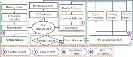
Fig.3 Flowchart of experiment.

Fig.4 Velocity distribution of separated flow around SC1095 airfoil(α=18°).
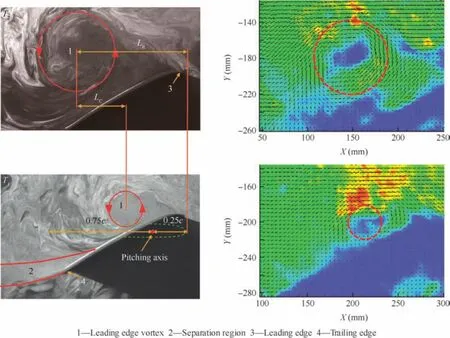
Fig.5 Calculation of convective velocity of LEV.
2.Experimental setup and procedure
2.1.Experimental equipment
Two typical helicopter rotor airfoils,OA209 airfoil and SC1095 airfoil,are selected to compose the blade sections in this experiment.As shown in Fig.1,it can be noticed that the SC1095 airfoil has a larger leading edge radiusrLEcompared with the OA209 airfoil.The schematic of the experiment is shown in Fig.2.It is illustrated that the main equipment of this dynamical stall experiment includes wind tunnel system,rotor blade models,PIV system and other auxiliary equipment.The wind tunnel is an open-return design with 2.4 m×3.4 m×5.0 m test section,and the maximum free stream velocity is 50 m/s.The span length and chord length of the blade models are 0.5 m and 0.2 m,respectively.The effective pixels of the CCD camera employed in this experiment is 1600×1200 and the measurement area of the CCD camera is 0.338 m×0.450 m.

Fig.6 Comparisons of flowfield under light dynamic stall condition at low oscillating frequency(V∞=5 m/s).

Fig.7 Comparisons of flowfield under light dynamic stall condition at low oscillating frequency(V∞=10 m/s).

Fig.8 Comparisons of flowfield under light dynamic stall condition at low oscillating frequency(V∞=15 m/s).
2.2.Experimental conditionsThe main target of this experiment is to measure the characteristics of LEV of airfoil.In order to satisfy the feasibility of this dynamic stall experiment,the moving manner of the rotor blade is reasonably simplified.As a result,the important pitching motion remains and the subordinate flapping motion is ignored.The experiment of rotor airfoil dynamic stall was conducted atdifferentfree stream velocities,oscillating frequencies and angles of attack,and the test states of the experiment are provided in Table 1.
The flowchart of this experiment is shown in Fig.3.The sinusoidal vibration of rotor blade model is driven by motor which is controlled by frequency controller.Both the laser and CCD camera are controlled by the computer of PIV system,and the signal synchronizer ensures the laser and CCD camera working at the same frequency.
2.3.Experimental verification
In order to verify the effectiveness of PIV technology used in flowfield measurement of rotor airfoil,the measurement of the SC1095 airfoil under steady condition was accomplished before the dynamic stall experiment.The free stream velocity of the steady experiment was fixed at 20 m/s,and the angle of attack of 18°(separated flow condition)was selected in this measurement.The measured results are shown in Fig.4(a),and the numerical results simulated by FLUENT software at the same condition are shown in Fig.4(b).From this instance,it can be observed that the magnitude of the flowfield velocity and the range of separated region calculated by the CFD method agree well with the results measured by the PIV technology.It is demonstrated that the PIV technology can be effectively employed to measure the flowfield velocity of rotor airfoil.
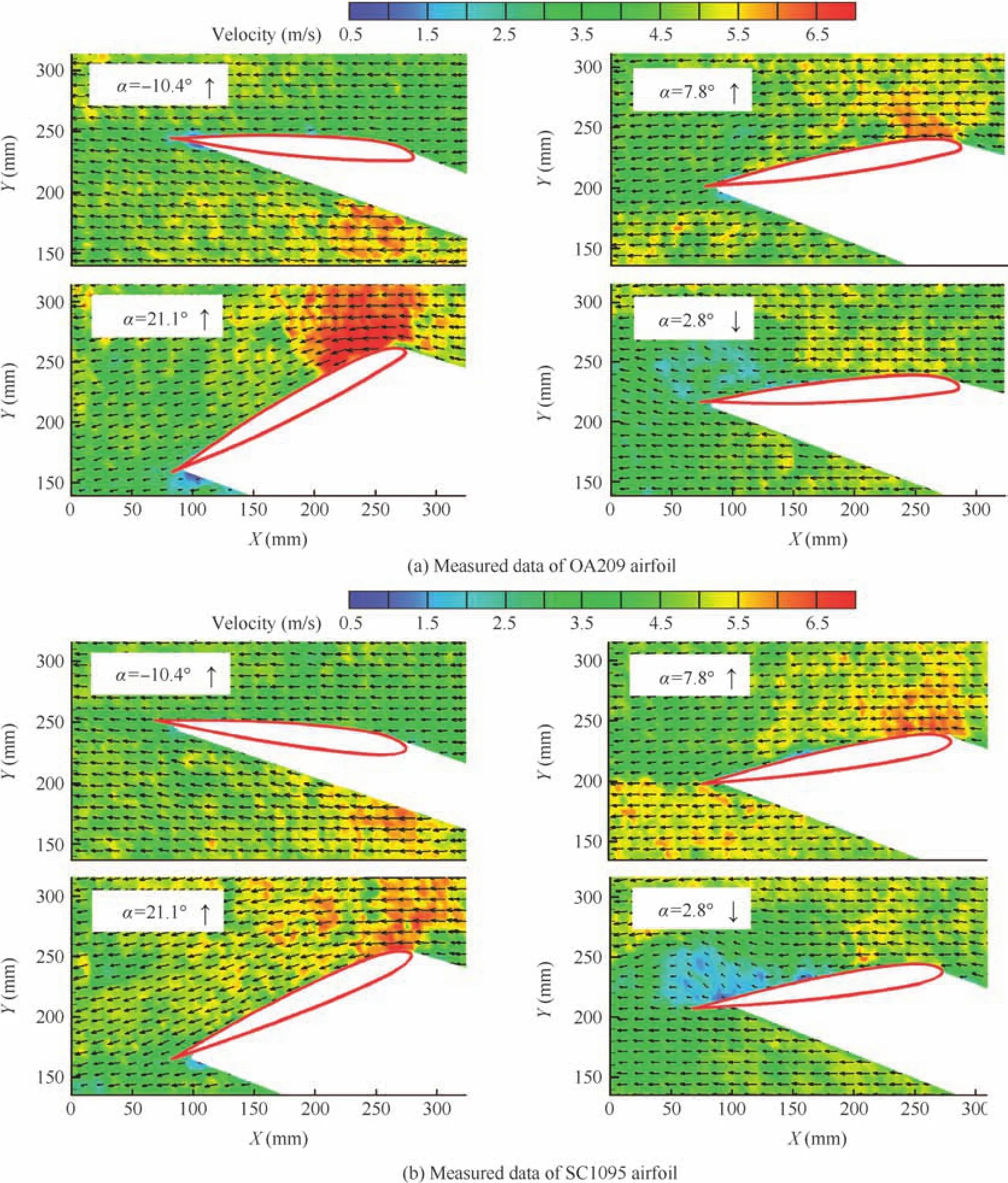
Fig.9 Comparisons of flowfield under light dynamic stall condition at high oscillating frequency(V∞=5 m/s).

Fig.10 Comparisons of flowfield under light dynamic stall condition at high oscillating frequency(V∞=10 m/s).
3.Measured results and analyses
The instantaneous original images taken by CCD camera of PIV system are shown on the lift side of Fig.5,and the velocity distributions of the flowfield around the LEV are shown in the right side of Fig.5.It can be noticed that the smoke stream basically displays the characteristics of airflow around airfoil,such as LEV,separation regions,etc.In order to illustrate the physical characteristics of the unsteady flowfield around airfoils,10 high-quality samples of the flowfield were picked out from about 30 measured data to calculate the final results at the same angle of attack(AoA)in different vibration cycles,and the velocities of flowfield were calculated by the crosscorrelation method.
TheLRshowninFig.5representstherelativepositionofLEV,and the data is nondimensionalized by the chord lengthcof airfoil.Because the sample frequency of the PIV system is fixed at 10 Hz,the time interval betweenT1(earlier time)andT2(later time)is 0.1 s.Therefore,the convection velocity of the LEV can be conveniently estimated by measuring the convection distanceLCof the LEV.In order to reflect the strength of the LEV,the circulationoftheLEVisestimatedbasedontheintegrationalong the LEV,and the estimated formula can be written as

where Γ represents the circulation of vortex,V the flowfield velocity along the integral curve,and ds the micro-segment of the integral curve.In order to accomplish the calculation of the circulation,the integration could be expressed as a summation,i.e.,

whereNdenotes the number of micro-segment.
3.1.Flowfield measurement at dynamic stall condition
3.1.1.Light dynamic stall at low oscillating frequency
The PIV measurement results of two types of rotor airfoil at different free stream velocities are shown in Figs.6–8,the oscillating frequency of this case is 1.6 Hz,and the reduced frequencies at different free stream velocities are 0.201(5 m/s),0.1 (10 m/s), and 0.067 (15 m/s), respectively. The α=4.9°+15.7°sin(2πft),wheretis oscillation time.It is noticed that the airflow is basically attached on the surface of both the OA209 airfoil and the SC1095 airfoil under these unsteady conditions,but separation regions appear nearby the trailing edge of the airfoils when the blade models are pitching down,and the strength of the separation region is mainly alleviated with the decrease of the reduced frequency.Another feature of the flowfield should be noticed is that there is no obvious LEV shed from the leading edge of the two different airfoils under the conditions of the measurement.

Fig.12 Comparisons of flowfield under deep dynamic stall condition at low oscillating frequency(V∞=5 m/s).

Fig.13 Comparisons of flowfield under deep dynamic stall condition at low oscillating frequency(V∞=10 m/s).

Fig.14 Comparisons of flowfield under deep dynamic stall condition at low oscillating frequency(V∞=15 m/s).
3.1.2.Light dynamic stall at high oscillating frequency
The measured results at higher oscillating frequency(2.4 Hz)ofthe measurementare shown in Figs.9–11,and α=5.2°+16.1°sin(2πft).In this case,the reduced frequencies at different free stream velocities are 0.302(5 m/s),0.151(10 m/s),and 0.101(15 m/s),respectively.It is noticed that the LEV is not observed in both the SC1095 airfoil and the OA209 airfoil under these unsteady conditions.Meanwhile,it can also be observed that the acceleration phenomenon around the leading edge of the OA209 airfoil is more obvious than that of SC1095 airfoil since the leading edge radius of the OA209 is smaller.As the freestream velocity increases,it is illustrated that the separated region of the flow field is mainly reduced with the decrease of the reduced frequency.
3.1.3.Deep dynamic stall at low oscillating frequency
Compared with Case 3.1.1,the mean pitching angle of the blade model in this case is enlarged by about 5°,i.e.,α=10.0°+15.8°sin(2πft),the oscillating frequency of the blade model keeps at 1.6 Hz,and the reduced frequencies for different free stream velocities are the same as the data in the Case 3.1.1,i.e.,0.201(5 m/s),0.1(10 m/s),and 0.067(15 m/s).The measurement results of the airfoil flowfield at different free stream velocities are shown in Figs.12–14,respectively.It is illustrated that the LEV of airfoil is well captured when it is shed from the leading edge of airfoil.The circulation of the LEV of the OA209 airfoil in Fig.12 at the AoA of 26.6°is 0.586 m2/s,and the LEV circulation of the SC1095 airfoil at the same AoA is 0.487 m2/s(with the same radius of integration),therefore,it is indicated that the LEV of OA209 airfoil is stronger than the LEV of the SC1095 airfoil.This phenomenon may be attributed to the reason that the leading edge radius of the OA209 airfoil is smaller than the leading edge radius of the SC1095 airfoil,because the adverse pressure gradient of airfoil with smaller leading edge radius is usually sharper than that of larger leading edge radius.As the free stream velocity increases from 5 m/s to 15 m/s,the position of the LEV at the same AoA moves to the trailing edge of airfoil gradually,and the relative position of LEV(nondimensionalized by chord length of airfoil)are shown in Fig.15.It can be seen that the convection velocity of the LEV is obviously influenced by free stream velocity,but the convection velocity of LEV is insensitive for different airfoils.
3.1.4.Deep dynamic stall at high oscillating frequency
The measurement results of flowfield at different free stream velocities under deep dynamic stall conditions are shown in Figs.16–18,respectively.In this case,the oscillating frequency of the measurement increases to 2.4 Hz,meanwhile the α =10.1°+16.2°sin(2πft)and the reduced frequencies remain the same value of the Case 3.1.2.For the case of free stream velocity of 5 m/s,the LEV circulation of the OA209 airfoil at AoA of 26.1°is 0.684 m2/s,and the LEV circulation of the SC1095 airfoil under the same condition is 0.445 m2/s.It is indicated that the vortex strength of the OA209 airfoil is larger than that of the SC1095 airfoil.As a result,the induction of the LEV of the OA209 airfoil is more obvious compared with theSC1095airfoil.Therefore,thevelocity distribution nearby the upper surface of OA209 airfoil is generally larger than the velocity distribution of SC1095 airfoil.The relative position of LEV is shown in Fig.19 and it also can be seen that the relative position is enlarged gradually with the increase of the free stream velocity.
3.2.Calculation of convection velocity of vortex
The measured results of the LEV convection velocities at free stream velocity of 5 m/s are shown in Fig.20,and the reduced frequencies at different oscillating frequencies are 0.201(1.6 Hz)and 0.302(2.4 Hz).It is indicated that the convection velocity of the LEV is obviously smaller than the free stream velocity,and the dimensionless convection velocity of the LEV is about 0.4.It can also be seen that the convection velocity of LEV has no remarkable difference between the OA209 airfoil and the SC1095 airfoil in the same measurement state,but the convection velocity has slight difference for different reduced frequencies.The convection velocity of LEV at higher reduced frequency is larger than the value at lower reduced frequency,because the vortex is more easily separated from the upper surface of airfoil under severe unsteady condition,i.e.,higher reduced frequency.
In order to investigate the characteristics of the LEV,the convection velocity of LEV at different relative locations is shown in Fig.21(the measurement state is the same as Case 3.1.3 with the free stream velocity of 5 m/s).It is noticed that the convection velocity of LEV is separated into two different groups,named as surface vortex and wake vortex,respectively.The surface vortex represents that the LEV still attaches on the surface of airfoil,and the wake vortex represents that the LEV has been separated from the surface of airfoil.It can be seen that the convection velocity of LEV is not a constant value and accelerated when it sheds from the leading edge of airfoil.The convection velocity of surface vortex is distributed among the velocity range of 1.5–2.6 m/s,and the value of wake vortex is distributed among the velocity range of 2.2–3.5 m/s.In order to indicate the relationship between convection velocity of LEV and free stream velocity,the average convection velocity of LEV is nondimensionalized by the free stream velocity,and the results are 0.39 for surface vortex and 0.55 for wake vortex,respectively.As the reduced frequency of the blade model increases,the LEV might be separated from the surface of airfoil more easily,and as a result,the convection velocity of LEV increases.
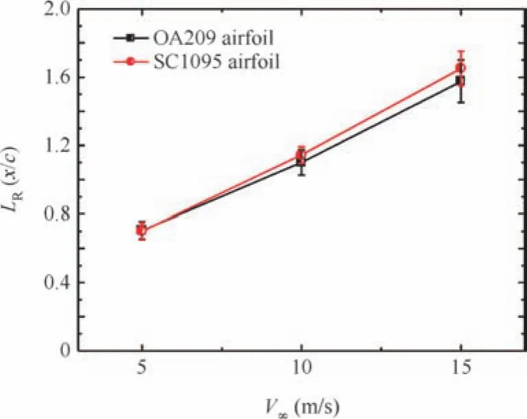
Fig.15 Comparison of relative position of LEV between OA209 airfoil and SC1095 airfoil at low oscillating frequency.

Fig.16 Comparisons of flowfield under deep dynamic stall condition at high oscillating frequency(V∞=5 m/s).
4.Conclusions
A new dynamic stall experiment of typical rotor airfoil OA209 and SC1095 was accomplished,and the LEV of airfoil was measured under different dynamic stall conditions by employing advanced PIV technology.Meanwhile,the convection velocity ofLEV isalso estimated in this experiment.
(1)Although the shape of airfoil has no obvious influence on the convection velocity of LEV,it can still effectively influence the strength of LEV.The airfoil with larger leading edge radius could inhibit the LEV,because the airfoil with larger leading edge radius would notably decrease the adverse pressure gradient of airfoil near the leading edge which would influence the critical condition of LEV.
(2)The reduced frequency can influence the convection velocity of LEV.By enlarging the reduced frequency of airfoil,the convection velocity of LEV would increase gradually.
(3)The AoA of airfoil can significantly influence the dynamic stall characteristics and the LEV could be inhibited by reducing the AoA.Because there is no obvious LEV observed under the condition of small AoA,the influence of the AoA on the convection velocity is still unknown.
(4)The convection velocity of LEV is associated with the free stream velocity,and it will increase when the free stream velocity increases.Meanwhile,the convection velocity of LEV is time variant value and it would increase when it convects to the trailing edge of airfoil.

Fig.17 Comparisons of flowfield under deep dynamic stall condition at high oscillating frequency(V∞=10 m/s).
Due to the limitation of the experimental equipment,the information of convection velocity at higher free stream speed is not included in this experiment,but it would be one of the investigations about dynamic stall of airfoil in the future.

Fig.18 Comparisons of flowfield under deep dynamic stall condition at high oscillating frequency(V∞=15 m/s).

Fig.19 Comparison of relative position of LEV between OA209 airfoil and SC1095 airfoil at high oscillating frequency.
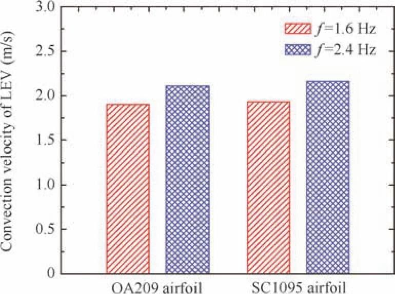
Fig.20 Convection velocity of LEV at free stream velocity of 5 m/s.

Fig.21 Distribution diagram of LEV convection velocity.
Acknowledgment
This research was supported by the National Natural Science Foundation of China(No.11272150).
1.Conlisk AT.Modern helicopter aerodynamics.Annu Rev Fluid Mech1997;29:515–67.
2.Leishman JG.Principles of helicopter aerodynamics.2nd ed.New York:Cambridge University Press;2006.p.525–59.
3.Geissler W,Haselmeyer H.Investigation of dynamic stall onset.Aerosp Sci Technol2006;10(7):590–600.
4.Mulleners K,Kindler K,Raffel M.Dynamic stall on a fully equipped helicopter model.Aerosp Sci Technol2012;19:72–6.
5.Choudhry A,Leknys R,Arjomandi M,Kelso R.An insight into the dynamic stall lift characteristics.Exp Therm Fluid Sci2014;58(4):188–208.
6.Gardner AD,Richter K.Influence of rotation on dynamic stall.J Am Helicopter Soc2013;58(3):1–9.
7.Chen PC,Bhasin S.ZONA6 versus the Doublet-Lattice method for unsteady aerodynamics on lifting surfaces.J Aircr2012;48(3):966–8.
8.Qureshi H,Hamdani HR,Parvez K.Effects on dynamic stall on cambered airfoil with drooping leading edge control.44th AIAA aerospace sciences meeting and exhibit.Reston:AIAA;2006.
9.Visbal MR.Numerical investigation of deep dynamic stall of a plunging airfoil.AIAA J2011;49(10):2152–70.
10.Gardner AD,Richter K.Influence of rotation on dynamic stall.68th American Helicopter Society annual forum.Alexandria:AHS International;2012.
11.Liu J,Sun HS,Liu ZT,Xiao ZX.Numerical investigation of unsteady vortex breakdown past 80°/65°double-delta wing.Chin J Aeronaut2014;27(3):521–30.
12.McCroskey WJ,Carr LW,McAlister KW.Dynamic stall experiments on oscillating airfoil.AIAA J1976;14(1):57–63.
13.McAlister KW,Carr LW,McCroskey WJ.Dynamic stall experiments on the NACA0012 airfoils.Washington,D.C.:NASA;1978.Report No.:NASA/TP-1100.
14.Rhee MJ.A study of dynamic stall vortex development using twodimensional data from the AFDD oscillating wing.Washington,D.C.:NASA;2002.Report No.:NASA/TM-2002-211857.
15.Sun M,Wang JL,Lian QX.A study of the flow structure around a constant-rate pitching airfoil.Chin J Theor Appl Mech1992;24(5):517–21.
16.Baik YS,Rausch JM,Bernal LP.Experimental investigation of pitchingand plunging airfoils at Reynolds numberbetween 1×10⁴ and 6×104.39th AIAA fluid dynamics conference.Reston:AIAA;2009.
17.Zanotti A,Melone S,Nilifard R,D’Andrea A.Experimentalnumerical investigation of the retreating blade dynamic stall.68th American Helicopter Society annual forum.Alexandria:AHS International;2012.
18.Naughton J,Strike J,Hind M,Magstadt A,Babbitt A.Measurements of dynamic stall on the DU wind turbine airfoil series.69th American Helicopter Society annual forum.Alexandria:AHS International;2013.
19.Leishman JG,Beddoes TS.A generalized model for unsteady airfoil behavior and dynamic stall using the indicial method.42nd American Helicopter Society annual forum.Alexandria:AHS International;1986.
20.Leishman JG,Beddoes TS.A semi-empirical model for dynamic stall.J Am Helicopter Soc1989;34(3):3–17.
16 March 2015;revised 18 June 2015;accepted 16 July 2015
Available online 5 March 2016
ⓒ2016 Chinese Society of Aeronautics and Astronautics.Published by Elsevier Ltd.This is an open access article under the CC BY-NC-ND license(http://creativecommons.org/licenses/by-nc-nd/4.0/).
*Corresponding author.Tel.:+86 25 84893753.
E-mail addresses:mingqingwq@nuaa.edu.cn(Q.Wang),zhaoqijun@nuaa.edu.cn(Q.Zhao).
Peer review under responsibility of Editorial Committee of CJA.
Wang Qingis a Ph.D.candidate in aircraft design at Nanjing University of Aeronautics and Astronautics,and his main research interests are aerodynamic shape optimization of rotor airfoil and rotor blade,unsteady aerodynamics and helicopter CFD.
Zhao Qijunis a professor and Ph.D.supervisor in the College of Aerospace Engineering at Nanjing University of Aeronautics and Astronautics,where he received his Ph.D.in aircraft design.His main research interests are helicopter CFD,helicopter aerodynamics,aerodynamic shape design of rotor blades,active flow control of rotors,and rotor aeroacoustics.
杂志排行
CHINESE JOURNAL OF AERONAUTICS的其它文章
- Hypersonic starting flow at high angle of attack
- Advances and trends in plastic forming technologies for welded tubes
- Instability and sensitivity analysis of flows using OpenFOAM®
- Numerical simulations of high enthalpy flows around entry bodies
- Modeling and simulation of a time-varying inertia aircraft in aerial refueling
- Experimental investigations for parametric effects of dual synthetic jets on delaying stall of a thick airfoil