Nonlinear flutter wind tunnel test and numerical analysis of folding fins with freeplay nonlinearities
2016-11-21YangNingWangNanZhangXinLiuWei
Yang Ning,Wang Nan,Zhang Xin,Liu Wei
Beijing Institute of Electronic System Engineering,Beijing 100854,China
1.Introduction
Due to the increased requirements for storage space and firepower,folding wing structures are widely used in missiles.Although torsion springs and dowels are used to strengthen a structure in the folding axes,nonlinear phenomena of free-play and frictions always exist because of the mismachining tolerance and attrition.
Because of the existence of structural nonlinearities,the characteristics of vibration and aeroelasticity are changed.The aeroelastic characteristics cannot be analyzed precisely by the traditional linear methods in some situations,and the design process is affected.In recent years,many investigations of nonlinear aeroelastic analysis have been performed.A review on the recent advances in nonlinear aeroelasticity of aircraft was presented by Xiang et al.1and the research aeroelastic models with freeplay nonlinearity are mainly airfoils.A three-degree-of-freedom(DOF)airfoil with nonlinearity in the pitch degree was investigated by Li et al.2The results showed that limit cycle oscillations(LCOs)occurred and based on the state-dependent Riccati equation method,a state feedback suboptimal control law was derived to suppress the vibration.A three-DOF airfoil with a nonlinear torsional spring was investigated by Alighanbarietal.3,4and bifurcations and LCOs were observed under the linear flutter boundary by Fourier transform.The nonlinear flutter characteristics of two-DOF foils were researched by Price and Lee.5LCOs and chaos motions occurred under the linear flutter boundary,and the vibration characteristics were related to the structural parameters and initial conditions.A series of two-DOF foils with freeplay and frictions in the torsion direction were investigated,and wind tunnel tests were performed by Yang.6Similar research on two-or three-DOF foils is abundant.In these studies,nonlinear aeroelastic phenomena and nonlinear analysis methods have been emphasized.However,the actual mechanisms are multi-DOF structures,and analysis methods are dif ficult to apply in actual cases.
The existence of freeplay makes the relationship between structural stiffness and generalized coordinates nonlinear.As a consequence,the results calculated by the linear modal method may differ from real phenomena.Kan and Patrick investigated the impact of freeplay on the flutter and LCO of an all-movable horizontal tail by adding a gap element at the root,and the calculated flutter/LCO characteristics matched the experimental data.7To establish the nonlinear vibration equation,a fictitious mass method was introduced by Karpel et al.8,9In this method, fictitious modals are obtained by modal analysis of a structure with a fictitious mass in the DOFs where the stiffness values are changed.The fictitious mass method is widely used in nonlinear aeroelastic analysis.Lee and Kim analyzed an all-movable nonlinear control fin,10and the results showed that the nonlinear parameters and initial conditions had strong in fluences on the nonlinear responses.Different velocities and different ratios between the freeplay and the vibration amplitude caused the vibrational responses to be LCO or chaos motions.Bae et al.established the nonlinear aeroelastic equation of a wing-aileron mode,and the nonlinear characteristics were analyzed.11LCOs occurred under the linear flutter boundary.Lee et al.performed a study on a folding wing with freeplay and friction nonlinearities,12,13and LCOs were observed.Lee and Tron conducted a study of the aeroelastic characteristics of an F-18 by the fictitious mass method.14The results showed that LCOs occurred within a small range,and the angle of attack could suppress vibrations.Although a nonlinear equation could be established by the fictitious mass method,the selected parameters of the fictitious masses are in a suggested range,and the nonlinear stiffness is not directly expressed in the equation.
As the previous introduction shows,research about the numerical analysis of the nonlinear aeroelastic characteristics is suf ficient,but the literature about nonlinear flutter wind tunnel tests of missile control fins is limited.Although the con figurations of folding wings are different from those of missile control fins,wind tunnel tests of folding wings could provide references.The test vibration responses in the wind tunnel environment could be used to verify the analysis method.An investigation was made into the nonlinear aeroelastic behavior of a composite wing with a morphing trailing edge by Li et al.15The results showed that the freeplay nonlinearity might reduce the convergence speed and accelerate the divergence of aeroelastic responses.Sebastiano and Sergio investigated the effect of the control-surface freeplay on the aeroelastic characteristics and a wind-tunnel model of a T-tail with freeplay.16A state-space system with nonlinearity was represented as a feedback loop and a high-order harmonic balance approach was performed to simulate the experimental results.The experimental results and the calculated frequency response function(FRF)and LCO were in agreement.Tang and Dowell performed wind tunnel tests of a folding wing,and the results showed that the flutter speed was related with the folding stiffness and folding angles.17However,in Tang’s experiment,there was no freeplay in the folding structure,and the flutter speed was the linear result.To observe nonlinear flutter and flutter suppression technique,a three-DOF foil mode with freeplay in the pitching direction was designed,and wind tunnel tests were conducted by Texas University.18–20The results of the wind tunnel tests showed that LCOs were observed because of the freeplay.Although the wind tunnel tests of the foils indicated nonlinear flutter and veri fied the analysis method,the phenomena between the foils and the folding structures are different and the modeling method of the folding wing is more complex.As a result,nonlinear flutter wind tunnel testing for the folding fin is necessary.
In the present work,a series of folding fins with different freeplay angles is designed,and a nonlinear flutter wind tunnel test is conducted.The nonlinear phenomena are observed by accelerometersand a high-speed cameras.By thefreeinterface component mode synthesis method,a nonlinear aeroelastic governing equation is established by the expansion of the connected conditions.Based on the results of the wind tunnel test,the flutter analysis of the tested folding wings with different freeplay angles is performed.
2.Computation scheme
A folding wing can be separated into two parts:the inner wing and the outboard wing.Therefore,the component mode synthesis method is an effective method to establish the governing equation.The component mode synthesis method was first introduced by Hurty.21,22Craig and Bampton expanded the method and introduced the fixed-interface component mode synthesis method,which was an effective engineering method.23Then,the free-interface component mode synthesis method was introduced by Hou,24and developed by Rubin25and Craig and Chang.26In the developed method,the residual modals are added into the calculation,which eliminates the effects caused by neglecting the higher modals.

Fig.1 Process of component mode synthesis method.
In the traditional free-interface component mode synthesis method,the elastic connection and the nonlinear internal force might not be considered.In the present work,the free-interface component mode synthesis method is developed and used to establish the nonlinear aeroelastic equation.The procedure for determining the nonlinear aeroelastic governing equation is shown in Fig.1.
The dynamic equation of a substructure under physical coordinates can be written as

where M the mass matrix,K the stiffness matrix,u the physical coordinates.f*is the external force applied to every node,fJis the internal force applied to the connected DOFs,and B is the projection matrix.
The calculated DOFs of the equation under physical coordinates can be reduced by modal coordinates.The kept component modals Φkare in the free-free states and the residual modals are Ψd,of which the generalized coordinate is the internal force fJ.Consequently,the physical coordinates of the substructures are reduced to

where pkthe generalized coordinate of the kept modals Φk.Coordinate transformation is used to decouple the equation,which under the generalized coordinates is expressed as

where Ikthe generalized mass matrix.Λkis the generalized stiffness corresponding to the kept modals,Mdis the coupled mass matrix,and Kdis the coupled stiffness matrix.pkand fJare the generalized coordinates corresponding to the retained and residual modals,respectively.The solution method for the residual modals is written as


Based on the traditional connected condition,the connected method is

If connected areas exist between substructures,the corresponding coordinates are not equal and there are relative shifts δ.However,the inner forces are equal because of interaction forces.By substituting Eq.(2)into the coupled conditions,the equality of the displacements can be written as

The internal force can be expressed by the parameter δ,which has no relation to the other generalized coordinates and is retained in the dynamic equations,i.e.,
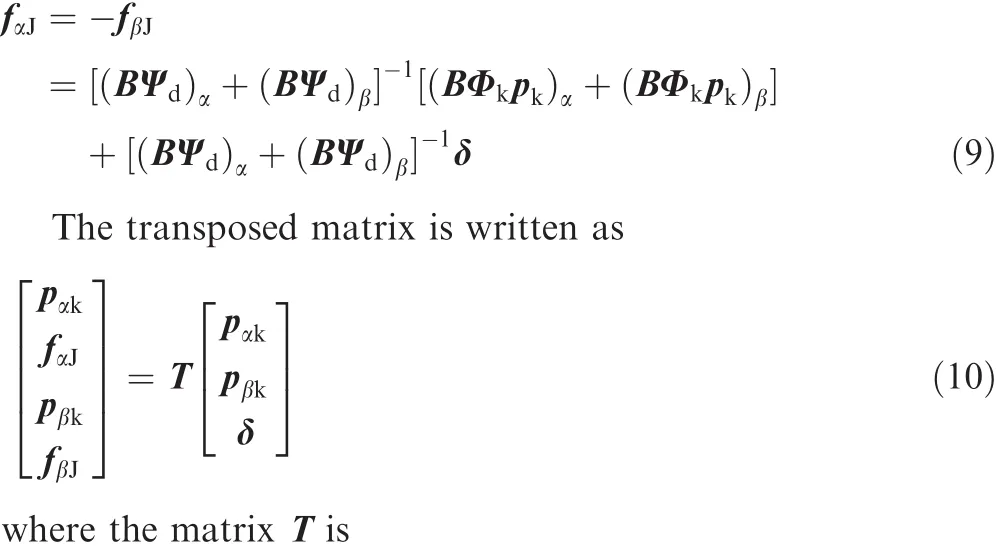

Fig.2 Sketch of experimental fin.

Fig.3 Structure and measured points.


In the coupled equation,the mass and stiffness matrices are coupled,but the calculated DOFs are reduced and the computational ef ficiency is acceptable.In Eq.(12),the generalized forces corresponding to the coordinates pαkand pβkare zero,which is the conclusion of the conventional method.The generalized force related to the generalized coordinate δ is deduced as

The third item of the generalized force is retained in the equation,the elastic connected force is considered,and the coupled dynamic equation is written as

In general,the inner force is related to the displacement shift δ.For a linear case,the generalized force is the product of the generalized displacements and the linear stiffness,namely,fβJ=keδ.keis the linear stiffness.The dynamic equation is

For nonlinear conditions,the restoring force is the nonlinearfunction ofthegeneralized displacements,namely,fβJ=knon(δ)δ.knon(δ)is the nonlinear stiffness.
In actual structures,there are only a few DOFs connected by elastic structures,and the coupled conditions of most DOFs are fixed.For example,in folding wing structures,only the DOFs rotated around the hinge axis are coupled flexibly.Therefore,the coupled conditions should be distinguished,and the generalized displacements are connected.28
To increase the computational ef ficiency,the modal coordinates are used in the aeroelastic analysis.In the present method,the modals are constituted by the kept and residual modals.The modals that are used to calculate the nonsteady aerodynamic force are shown as

The aerodynamic force in fluence coef ficient matrix Q is obtained,and the aeroelastic equation in the frequency domain is written as

where ρ is the air density,Vis the flight speed.For linear cases,thep-kandv-gmethods can be used to obtain the flutter characteristics.For nonlinear conditions,the calculation in the time domain provides more information about the nonlinear system.The rational function approximations are used to obtain the aerodynamic matrix in the time domain.29The form of this method in the Laplace domain is written as

where A is the generalized aerodynamic in fluence coef ficient matrix.Q0,Q1and Q2are the aerodynamic coef ficient matrice in time domain.sis the Laplace symbol.The aeroelastic equation in the time domain is expressed as


Fig.4 Sketch of installation of structures in wind tunnel.
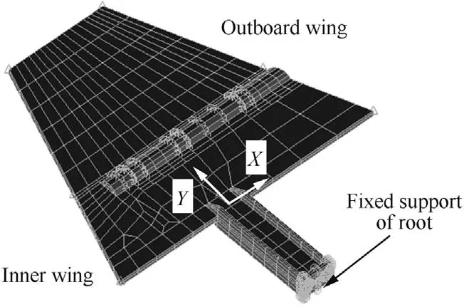
Fig.5 FE model of structure.

Table 1 Mass properties of FE model.
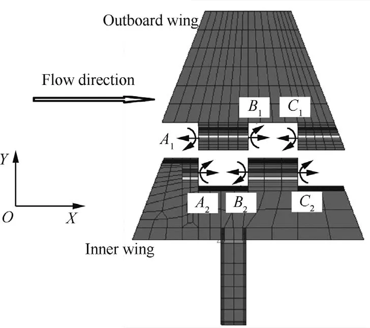
Fig.6 Connection between inner wing and outboard wing of FE model.
wherebis the reference chord length.In the wind tunnel environment,the aerodynamic load includes the aerodynamic force caused by the angle of attack and the gravity force,and the equation should consider these in fluences,which is shown as


Table 2 Three freeplay situations.
where B1is the aerodynamic load caused by the angle of attack,and θ is the angle of attack.B2is the gravity vector,andGis the structural quality.The equation is written in a simple form as
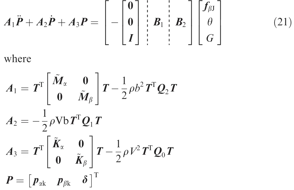
Based on the equation in the time domain,the state-space equation is established.The itemis the state variable,and the variable x2is the output.The state-space equation is written as

In Eq.(22),the internal force fβJis a function of the state variable x2.In nonlinear conditions,the function is fβJ=ke(x2).

Table 3 GVT results of Fin 1 and corresponding results of FE model.
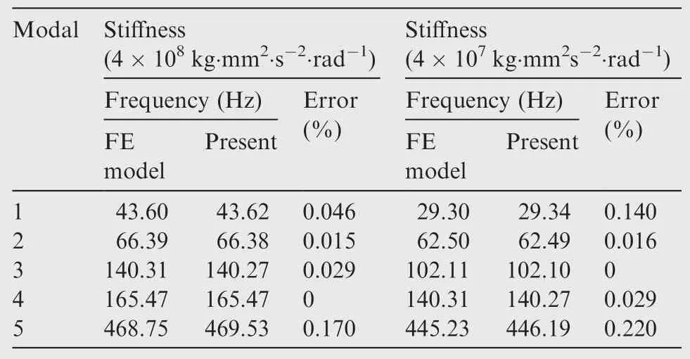
Table 4 Comparison between results of FE model program and present method when connected stiffness values are changed.

Fig.7 Wind tunnel test results of Fin 1.

Fig.8 Wreckage of Fin 1.
3.Presentation of results
3.1.Nonlinear flutter wind tunnel test
3.1.1.Experimental structure

Fig.9 Photos of a vibration period when vibrational divergence occurs.
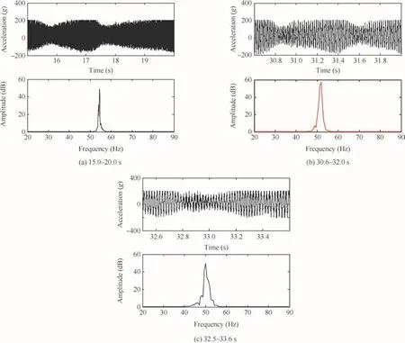
Fig.10 Accelerated responses of Fin 1 and Fourier transform at different time.
Based on the environment and the dimensions of the wind tunnel,an experimental fin is designed,as shown in Fig.2.The structure consists of an outboard wing,an inner wing,a rudder shaft,and a folding shaft,in which the rudder shaft and the inner wing are manufactured together,and the bottom of the rudder shaft is fixed on a rigid support structure by bolts.The experimental fin is made of aluminum.To obtain a flutter speed of the structure in the range of the ability of the wind tunnel,the rudder shaft is designed as an I-beam.The bend and torsional frequencies are also designed.The inner wing and the outboard wing are connected by the folding shaft The bending moment is transferred by the contact faces.The freeplay is generated by the manufacturing tolerance of the contact face between the inner wing and the outboard wing.The angle of the freeplay can be altered,and the freeplay has an in fluence on the bending modals.The vibrational responses are measured by accelerometers at the root and top of the trailing edge,as shown in Fig.3.
In actual flight conditions,a control fin is installed on the body of a missile.To simulate the actual aerodynamic force,a fin is installed in a rigid missile body,which is shown in Fig.4.The vibration process is recorded by a high-speed camera placed at the observation window.

Fig.11 Wind tunnel test results of Fin 2.
3.1.2.Finite element(FE)model and ground vibration test(GVT)
The FE model of the structure is established by Hex8 elements,which is shown in Fig.5.Based on the comparison between the FE model and the actual model,the FE model imitates the actual structure,as shown in Table 1.To simulate the in fluence of the folding shaft,three torsional springs in theXdirection are established,and the DOFs of other directions are connected rigidly,which is shown in Fig.6.In Fig.6,A1–A2B1–B2andC1–C2are the positions where springs are established.When there is freeplay in the folding shaft,the nonlinear springs are established by the method of the present work.In the present method,the inner wing and outboard wing are established as substructures,and the nonlinear vibrational governing equation is obtained by the developed free-interface component mode synthesis method.
Fins under the three freeplay conditions shown in Table 2 are tested in the wind tunnel.The connected faces shown in Fig.2 are welded,and the structure becomes a linear structure,which is the condition of Fin 1 in Table 2.The tested results of the linear structure are the references for the nonlinear tests.The distance between the connected faces is increased in Fin 2 and Fin 3 in Table 2,and the freeplay angles are increased.

Fig.12 Accelerated responses of Fin 2 and the Fourier transform at different time.

Fig.13 Wind tunnel test results of Fin 3.

Table 5 Test flutter results of three fins.
The GVT of Fin 1 structure is conducted,and test results are shown in Table 3.Based on the test results,the FE modelis modi fied.By revising the torsional springs in the FE model,the linear FE model can simulate the vibration characteristics of Fin 1.

Table 6 Flutter results of linear fin in frequency domain.
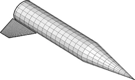
Fig.14 Model of aerodynamic force.
The nonlinear connected stiffness values change when the generalized coordinates change.As a consequence,to verify the accuracy of the present method,the results calculated by the present method and the FE model program are compared when the connected stiffness values are changed,as shown in Table 4.The results show that the present method is accurate when the stiffness changes.

Fig.15 Vibration responses of wingtip of linear fin when velocity is 190,210 and 211 m/s.
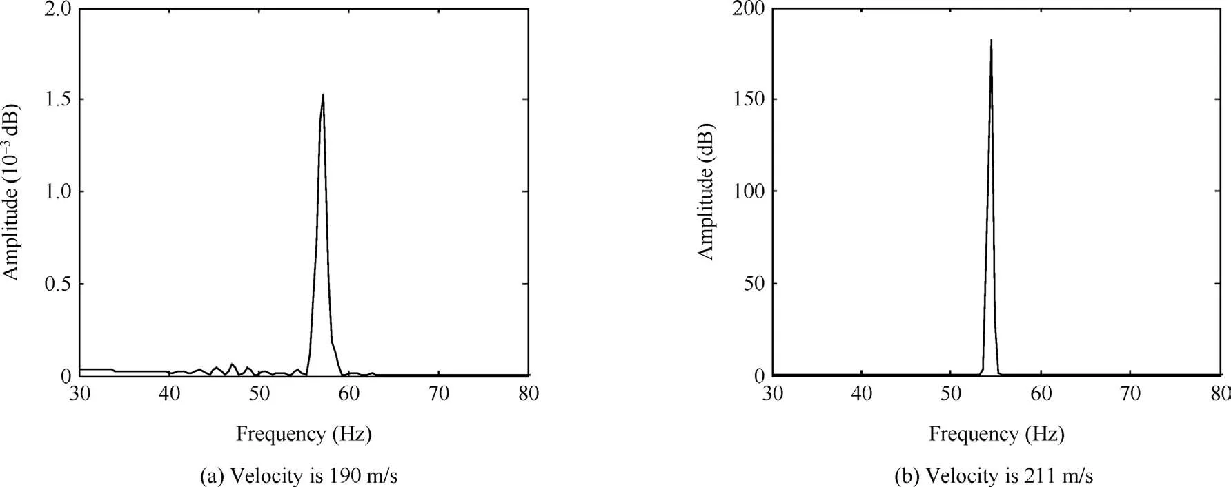
Fig.16 Fourier transform of response of wingtip when velocity is 190 and 211 m/s.

Fig.17 Numerical model of freeplay nonlinearity.
3.1.3.Results of nonlinear wind tunnel tests
The wind tunnel tests of the three fins are performed.The Mach number of the incoming flow of the wind tunnel is kept at 0.6.In the test process,the dynamic pressure of the incoming flow is increased gradually until the vibrational breakage of the structure,and each value of the dynamic pressure is maintained for a few seconds.In the test and numerical computation,the angle of attack is 0°.
The wind tunnel test of the linear Fin 1 is performed,and the result is shown in Fig.7.In the test process,the dynamic pressure is increased gradually as 24–26–28 kPa,and the vibrational responses are increased correspondingly,as shown by red and black lines,respectively.When the dynamic pressure is 26.94 kPa and the velocity of the incoming flow is 209.7 m/s,vibrational breakage of the fin occurs,and the responses of the accelerometers reach the measuring range.The wreckage of the fin is shown in Fig.8;the connection between the inner wing and the fin shaft and the root bolts are broken.Photos of the vibrational divergence are shown in Fig.9,and the sampling rate of the high-speed camera is 500 frame/s.

Fig.19 Selection process of initial values.
Fourier transform is performed on the vibrational responses to obtain the vibrational frequency,which is shown in Fig.10 The dynamic pressures of Figs.10(a)and(b)are 24 kPa and 26 kPa,respectively,and the corresponding vibrational frequencies are 54.82 Hz and 51.63 Hz.Along with the increase in the velocity,the vibrational frequency decreases.When divergence occurs,the vibrationalfrequency is 50.05 Hz,as shown in Fig.10(c).
Based on the test of the linear result,Fin 2 with freeplay is tested,as shown in Fig.11.The dynamic pressure is increased gradually as 24 kPa–26 kPa–28 kPa.The vibrational divergence occurs at the top of the adjustment process,of which the dynamic pressure is 30.68 kPa and the flow velocity is 223.8 m/s.The vibration responses are analyzed by Fourier transform,which is shown in Fig.12.Along with the increase in the velocity,the vibrational frequency decreases,which is the same as the results of Fin 1.There are LCOs in the vibration process,and the vibrational frequency decreases with increasing velocity.The vibrational amplitude increases along with the increase in the dynamic pressure,which is shown in Fig.12(a)and(b).
Fin 3 is tested using the same process,and the result is shown in Fig.13.The vibrational divergent dynamic pressure is 41.80 kPa,and the flow velocity is 261.2 m/s.LCOs are not observed in the test process,which might be due to the rapid increase in the dynamic pressure.

Fig.21 Fourier transform of vibration response of wingtip when freeplay angle is 0.10°.
The flutter results of the three fins are shown in Table 5.Along with the increase in the freeplay angle,the vibrational divergent speed increases,and the velocity is higher than that on the linear flutter boundary.The existence of freeplay causes the flutter speed of the present model to increase,and the linear calculation can ensure flight safety.Based on the comparison between Fin 1 and Fin 2,the vibrational divergent frequencies are almost the same.However,the flutter frequency of Fin 3 is lower due to the higher divergent speed.
3.2.Nonlinear flutter analysis
In this section,the aeroelastic characteristics of the linear structure are analyzed,and based on the results,the nonlinear cases are computed.For the current cases,the use of a precise nonlinear method to identify the nonlinear parameters of an engineering structure is rare in the literature.The freeplay angles of the fins designed in the present work are generated by mismachining tolerance.As a consequence,the trend of the values of the angles is af firmed.In the present numeral analysis,the values of the angles are chosen as 0.10°,0.15°,and 0.20°.
3.2.1.Analysis of linear condition
The flutter characteristics of the linear fin are analyzed in the frequency domain.The aerodynamic force is calculated by the ZONA6 method,in which the unsteady aerodynamic force of the body is considered,as shown in Fig.14.The referenced Mach number is 0.6,and the calculated aerodynamic density is 1.225 kg/s.2The flutter analysis method is thep-kmethod in the frequency domain.The results under different damping coef ficients are shown in Table 6.
In actual structures,there is structural damping,which increases the flutter speed.As shown in Table 6,different damping coef ficients result in different flutter speeds.When the damping coef ficient is 0.04,the calculated results imitate the test results,and the numerical method is precise.Based on the results in the frequency domain,the equation in the time domain is established in the present method.When the connected spring is linear,the results are shown in Figs.15 and 16.In Fig.15(a)and Fig.16(a),the vibrational frequency is 57.3 Hz when the velocity is 190 m/s,which is higher than the test result shown in Fig.10(c).When the calculated damp-ing coef ficient is 0.04,the flutter speed is 211 m/s,which is shown in Figs.15(b)and (c).The flutter frequency is 54.48 Hz,and the vibrational frequency is higher when the velocity is smaller,as shown in Fig.16.

Fig.22 Vibration response of wingtip when freeplay angle is 0.20°.
3.2.2.Analysis of nonlinear conditions
For nonlinear cases,the springs between the inner wing and the outboard wing are nonlinear freeplay springs,and the freeplay model is shown in Fig.17.Because the precise value of the freeplay angle is unknown,the calculated values are chosen as 0.10°,0.15°,and 0.20°.
(1)Determination of initial values
The initial values of the system have strong in fluences on thestructuralresponses.Smallinitialvaluescausethe responses to be convergent or LCO,and large initial values cause the responses to be divergent,as shown in Fig.18.When the initial values are within a speci fic range,the vibration of the structure is LCO and the amplitudes of the LCOs under different initial values are the same,as shown in Figs.18(a)and(b).In the environment of the wind tunnel,there are random perturbations observed in the aerodynamic pressure plots in Figs.7,11 and 13.In the present work,the same initial values are used during the calculations,and the calculated process of the initial values is shown in Fig.19 under a freeplay angle of 0.20°.
(2)Nonlinear analysis of fins with freeplay
A nonlinear fin with a 0.10°freeplay angle is analyzed.The results under different velocities are shown in Fig.20.The calculated divergent speed is 234 m/s,which could be obtained by Figs.20(c)and(d).By the Fourier transform,the vibration frequency is 51.2 Hz which is shown in Fig.21.
As shown in Figs.20(b)and(c),the LCOs occur when freeplay exists in the structure.The velocity when the LCO exists is between the linear flutter boundary and the divergent speed.When the velocity is slower than the linear flutter boundary,the vibration is convergent,which is shown in Fig.20(a).The vibrational frequency of the LCO decreases with an increase in velocity,which is shown in Figs.21(a)and(b).As shown in Figs.21(a)and(b),the vibrational energy under a velocity of 233 m/s is much higher than that under a velocity of 213 m/s,which is the same as the results of the wind tunnel test.
In the environment of the wing tunnel,random perturbations exist,and the random noise is applied to the calculation process,which is shown in Fig.20(e).Small perturbations cause the structure to experience a steady oscillation,and the amplitude of the LCO is affected.Based on comparison with the vibration under the same velocity shown in Fig.21(a)the vibrational frequency is not affected by the noise,as shown in Fig.21(c).Random perturbations affect the distribution of the vibrational energy of the LCO,and the principal vibrational frequency is the same as the results without the noise,which is shown in Figs.21(a)and(c).
A fin with a freeplay angle of 0.20°is analyzed using the same process.The divergent speed is 258 m/s,and the divergent frequency is 47.92 Hz,as shown in Figs.22 and 23.The divergent speed of the freeplay angle 0.20°is higher than that of the freeplay angle 0.10°,which is shown in Figs.20(d)and 22(b).LCOs exist when the velocity is between the linear flutter boundary and the divergent speed,which is shown in Figs.22(a)and(d).Based on comparison with the results of the freeplay angle 0.10°,the vibrational amplitude of the freeplay angle 0.20°is higher.The vibrational frequency decreases with increasing velocity,as shown in Figs.23(a)and(b).When the velocity is within the linear flutter boundary,the vibration is convergent,which is shown in Fig.22(c).As shown in Figs.23(a)and(b),the vibrational energy under a velocity of 257 m/s is much higher than the results under a velocity of 240 m/s,which is the same as the results of the freeplay angle 0.10°.
When small random noise is applied to the structure,the structure experiences steady oscillation,which is shown in Fig.22(e).Based on comparison with the Fourier transform shown in Fig.23(b),the vibrational frequency is not affected by the random noise.As in the same situation of the freeplay angle 0.10°,the distribution of the vibrational energy is affected and the energy of the principal vibrational frequency decreases,which is shown in Fig.23(c).
(3)Summary of the nonlinear analysis
A summary of the results of the wind tunnel test and the numerical analysis is shown in Table 7.The present method accurately simulates the flutter speed and the vibrational frequency.The relationship between the values of the freeplay angles and the flutter characteristics is the same as the results of the wind tunnel test.LCOs are observed in the results of both the analysis and the test.The trend between the vibrational frequency and the velocity is the same.The linear flutter boundary is the critical velocity whether LCOs occur,which is shown by the results of the experiment and the simulation.

Fig.23 Fourier transform of vibration response of wingtip when freeplay angle is 0.20°.

Table 7 Results of wind tunnel test and numerical analysis.
4.Conclusions
In this study,a wind tunnel test and numerical analysis of control fins with nonlinear folding stiffness are conducted.The conclusions are as follows:
(1)The divergence speed is increased by the existence of the freeplay when the angle of attack is 0°.A larger freeplay results in a higher divergent speed.Results based on the linear flutter analysis could ensure flight safety.The vibrational frequency decreases with increasing flow velocity.
(2)The nonlinear aeroelastic governing equation is established by the developed free-interface component mode synthesis method.The trends of the divergent and convergent speeds are the same as those in the wind tunnel test.The analysis method established by the present work could be used to calculate the vibrational characteristics of folding structures and the critical velocity could be predicted precisely.
(3)Whenthevelocityiswithinthelinear flutterboundaryand the divergent speed,LCOs exist.The vibration is convergentwhenthevelocityisbelowthelinear flutterboundary.
1.Xiang JW,Yan YJ,Li DC.Recent advance in nonlinear aeroelastic analysis and control of the aircraft.Chin J Aeronaut2014;27(1):12–22.
2.Li DC,Guo SJ,Xiang JW.Aeroelastic dynamic response and control of an airfoil section with control surface nonlinearities.Chin J Sound Vib2010;329:4756–71.
3.Alighanbari H.Aeroelastic response of an airfoil-aileron combination with freeplay in aileron hinge.J Aircr2001;39(4):711–3.
4.Alighanbari H,Hashhemi SM.Bifurcation analysis of an airfoil containing a cubic structural nonlinearity and subjected to twodimensional incompressible flow.43rd AIAA/ASME/ASCE/AHS/ASC structures,structural dynamics,and materials conference;2002 April;Colorado.Reston:AIAA;2002:AIAA-2002-1206.
5.Price SJ,Lee BHK.Postionstability behavior of a two-dimensional airfoil with a structure nonlinearity.J Aircr1994;31(6):1395–401.
6.Yang ZC.The experiment and theory analysis of the nonlinear lf utter[dissertation].Xi’an:Northwestern Polytechnical University,1987.[Chinese]
7.Kan N,Patrick H.Flutter and LCO of an all-movable horizontal tail with freeplay.53rd AIAA/ASME/ASCE/AHS/ASC Structures,Structural Dynamics,and Materials Conference;2012 April;Honolulu.Reston:AIAA;2012:AIAA-2012-1979.
8.Karpel M,Presente E.Structural dynamic loads in response to impulsive excitation.J Aircr1995;32(4):853–61.
9.Karpel M,Raveh D.Fictitious mass element in structural dynamics.AIAA J1996;34(3):607–13.
10.Lee I,Kim SH.Aeroelastic analysis of a flexible control surface with structural nonlinearity.J Aircr2003;32(4):868–74.
11.Bae JS,Yang SM,Lee I.Linear and nonlinear aeroelastic analysis of fighter-type wing with control surface.J Aircr2002;39(4):697–708.
12.Kim DK,Bae JS,Lee I.Dynamic model establishment of a deployable missile control fin with nonlinear hinge.J Spacecr Rockets2005;42(1):66–77.
13.Shin WH,Lee I.Nonlinear aeroelastic analysis for a control fin with an actuator.J Aircr2007;44(2):597–605.
14.Lee BHK,Tron A.Effects of structural nonlinearities on flutter characteristics of the CF-18 aircraft.J Aircr1989;26(8):781–6.
15.Li DC,Guo SJ,Xiang JW.Modeling and nonlinear aeroelastic analysis of a wing with morphing trailing edge.Proc Inst Mech Eng Part G J Aerosp Eng2013;227(4):619–31.
16.Sebastiano F,Sergio R.Freeplay-induced limit-cycle oscillations in a T-tail:numerical vs experimental validation.J Aircr2015;52(2):486–95.
17.Tang D,Dowell EH.Theoretical and experimental aeroelastic study for folding wing structures.J Aircr2008;45(4):1136–47.
18.Hill WJ,Strganac TW,Nichkawde C.Suppression of aeroelastic instability with a nonlinear energy sink:Experimental results.47rd AIAA/ASME/ASCE/AHS/ASC Structures,Structural Dynamics,and Materials Conference;2006 May;Newport.Reston:AIAA;2006.
19.Platanities G,Strganac TW.Control of a wing section with structural nonlinearities using leading and trailing edge control surfaces.43rd AIAA/ASME/ASCE/AHS/ASC Structures,Structural Dynamics,and Materials Conference;2002 April;Colorado.Reston:AIAA;2002.
20.Block JJ,Strganac TW.Applied active control for a nonlinear aeroelastic structure.J Guid Control Dynam1998;21(6):838–45.
21.Hurty WC.Vibration of structure systems by component mode synthesis.J Eng Mech Div1960;86(4):51–70.
22.Hurty WC.Dynamic analysis of structural systems using component modes.AIAA J1965;3(4):678–85.
23.Craig RR,Bampton MCC.Coupling of substructures for dynamic analysis.AIAA J1968;6(7):1313–9.
24.Hou SN.Review of model synthesis techniques and a new approach.Shock Vib Bull1969;4(4):25–30.
25.Rubin S.Improved component-mode representation for structural dynamic analysis.AIAA J1975;13(8):995–1006.
26.Craig RR,Chang CJ.On the use of attachment modes in substructure coupling for dynamic analysis.AIAA/ASME,18th structural dynamics and materials conference;1977 March;San Diego.Reston:AIAA;1977.p.89-99.
27.Craig Jr RR,Chang CJ.Substructure coupling in dynamic analysis and testing.Washington,DC:NASA;1977,Report No.:NASA CR-2781.
28.Wu ZG,Yang N,YANG C.Identi fication of nonlinear multidegree-of freedom structures based on Hilbert transformation.Sci China Phys Mech Astron2014;57(9):1725–36.
29.Tiffany SH,Karpel M.Aeroservoelastic modeling and applications using minimum-state approximations of the unsteady aerodynamics.Reston:AIAA;1989,Report No.:AIAA-1989-1188.
杂志排行
CHINESE JOURNAL OF AERONAUTICS的其它文章
- Plastic wrinkling prediction in thin-walled part forming process:A review
- Progress of continuously rotating detonation engines
- Microstructure control techniques in primary hot working of titanium alloy bars:A review
- A hybrid original approach for prediction of the aerodynamic coefficients of an ATR-42 scaled wing model
- Dynamic modeling and analysis of vortex filament motion using a novel curve- fitting method
- Boundary-layer transition prediction using a simpli fied correlation-based model
