Aeroelastic scaling laws for gust load alleviation control system
2016-11-21TangBoWuZhigangYangChao
Tang Bo,Wu Zhigang,Yang Chao
School of Aeronautic Science and Engineering,Beihang University,Beijing 100083, China
1.Introduction
The design of modern flights vehicles requires the evaluation of dynamic loads in response to discrete and random gust excitations.1The gust excitations may disturb the regular operations of pilots and worsen the ride quality.In more grievous cases,f
l ight mission cannot be completed and the flight safety maybe disserved.2Therefore,gust load alleviation becomes a key topic in aeroelastic problems.3
Gust load alleviation(GLA)control systems attempt to attenuate aircraft loads caused by the aircraft flying through gust zone.4Active control technology(ACT)has been proved to be useful for alleviating the internal loads and accelerations at some particular stations of the aircraft while in turbulence.5Some control theories such as the proportional–integral–deri vative(PID)control,the linear quadratic Gaussian(LQG)control,the H∞control and neuron-fuzzy control have been applied to GLA control system design and have been veri fied to be effective by numerical simulation.6,7
Compared to numerical simulation in theoretical study,wind tunnel test can provide a more real condition to validate GLA methods and control laws.In the aerodynamic ef ficiency improvement(AEI)program,GLA wind tunnel test on a semi span aeroelastic wind tunnel model was conducted.Two control methods(LQG control and LQR control)were employed in this effort and the peak wing bending moments due to gusts were successfully reduced by more than 50%.8,9Another work is the X-DIA aeroelastic test in Italy,which proved that adopting wing active control system can add damping to wing bending modes,either when wing was hit by discrete or stochastic gusts.10In China,studies on GLA wind tunnel test had been carried out by Wu et al.In this project,PID controller was applied to GLA and the accelerations at fuselage and wing tip were validated to be alleviated to a certain extent,as well as the bending moment of wing-root.11,12
Generally speaking,most GLA tests focus on studying the effectiveness of control methods and control laws.Some of the experimental models are speci fically built for the certain tests,and some are scaled from the full-scale aircraft.The scaled models in these tests might be similar to full-scale aircraft in structural stiffness,inertial mass and other aeroelastic parameters,but the scaling of GLA control systems is always beyond reach.
Aeroelastic scaled models are designed and manufactured so that the results obtained from the wind tunnel tests or flight tests can be related to the aeroelastic behavior of the full-scale aircraft.13The physical parameters of scaled model are determined by aeroelastic scaling laws established on the basic governing equations.Aeroelastic scaling laws, first presented by Bisplinghoff and Ashley,14have been developed and improved ever since.Recently,Wan and Cesnik have elaborated the aeroelastic scaling method of linear and nonlinear structures.In the area of aeroservoelastic scaling,Freidman studied a 2-D airfoil combined with a trailing edge control surface,derived aeroservoelastic scaling requirements for the fixed and rotary-wing aircraft.15,16And Pototzky applied scaling lawsto themodalformulation oftheaeroservoelastic equations,and veri fied the scaling process by comparing the root-locus of both size models.17
So far for GLA tests,the available aeroelastic scaling laws can only ensure the similarity of gust response under openloop condition.And no strict scaling laws have been put forward for GLA control system yet,which means the strict similarity of gust response under closed-loop condition is still unreachable.Note:the open-loop condition means that the GLA system does not work,while the closed-loop condition means the GLA system is taking effect.
The scaling laws of GLA control system are studied in this paper,along with some consideration for practical application.Starting from the aeroelastic equation of motion in generalized coordinates,the transfer function of a PID control system is derived.Through theoretical demonstration,a scaling criterion of the control system has been set up and a scaling method is provided and veri fied.The options of Froude number similarity have also been studied in this paper which gives us a more comprehensive understanding of the GLA scaling laws.In addition,considering the practical application,a compensating method is given for actuator or sensor when the theoretical scaled ones cannot be obtained.Another dif ficult problem,the scaling laws of saturations in actuator has been studied.All these scaling laws could be applied to GLA tests and play a critical role in making direct connections between scaled model and full-scale aircraft.
2.Scaling laws for GLA test model
The relations of gust response between the scaled model and the full-scale aircraft are governed by aeroelastic scaling laws.To meet the similarity of gust response of open-loop system,five general similarity criteria have been described in the following section.For closed-loop system,the general similarity criteria would not be suf ficient any more.Necessarily,the scaling criterion for GLA control system should be studied and method should be given to ensure the similarity of alleviation results.
2.1.General scaling method for aeroelastic similarity
For low-speed aeroelastic wind tunnel tests,there are no more than three practical constraints,corresponding to the primary dimensions of length,time,and mass.To specify these constraints,three factors are chosen as the basic scaling factors,including the length scaling factorkb,the speed scaling factorkVand the air density scaling factorkρ.18
On the basis of these three scaling factors,there are different criteria that should be satis fied in different situations when scaling a model.For example in flutter study,the dynamic aeroelastic equation of full-scale model can be written as follows(neglecting the damping)19:

where ω is the flutter frequency,Vthe air velocity,ρ the air density andbthe reference length.Generalized massM,generalized stiffnessKand generalized displacementqare dimensional and the aerodynamic in fluence coef ficientAis non-dimensional.Then the dynamic aeroelastic equation of scaled model can be written with the scaling factors:

Considering Eqs.(1)and(2),to get a similar flutter equation,the following similarity criterion is required:

Assuming that the Mach number,Reynolds number and speci fic heat ratio are the same between two models,and with similar aerodynamic con figuration and vibration shape,there will bekA=1,and thus let the non-dimensional parameter,the reduced frequencykbe kept the same in both model:

To summarize the similarity criteria for flutter test,basic scaling factors and other scaling factors according to the above criteria has been sorted in Table 1.13
The non-dimensional parameterskare kept the same in both models in order to ensure the flutter similarity.But in other kind aeroelastic scaling works,it would not be suf ficient any more.For example,the static aeroelastic or gust response similarities ask for one more non-dimensional parameter:the Froude number.Considering the effect of gravity,the static aeroelastic equilibrium equation can be written as
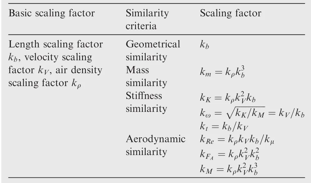
Table 1 Aeroelastic similarity criteria for flutter test.13

where α0is the initial angle of attack, αfthe angle of attack after elastic de flection,C1andC2are flexibility coef ficients.The equation of scaled model can be written as

So in static aeroelastic or gust wind tunnel test in which gravity provides one of the loads to achieve equilibrium,we can get similar criteria:
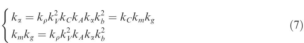
With the same angle of attackkα=1 and aforementionedkA=1,let another non-dimensional parameter,the Froude numberFrbe kept the same in both model

Neglecting the variation of the gravitational acceleration,the Froude number similarity can be expressed as follow:

The equation above consequently makes a connection between the two basic scaling factors:kVandkb,and turns the three basic factors into two:kρandkb.After the match of Froude number,the scaling factors derived from the similarity criteria are updated in Table 2,which provide the general scaling factors of a scaled model in gust related tests.
The scaling factors for shear forcekFSand bending momentkMEcan be obtained from the aerodynamic similarity:

wherekFAis the scaling factor for aerodynamic force.In addition,based on the equation of the second Newton law,thescaling factor for acceleration of a certain point can be obtained:

Table 2 Aeroelastic similarity criterions for gust related test.

Note the consistency of non-dimensional parameters:Reynolds number and Mach number are very important for the aerodynamics similarity.But Reynolds number requirement is often ignored because it is hard to reach in practical situations and is of minor importance as far as aeroelastic effects for main lifting surfaces are concerned.18Also,Mach number cannot be matched since the air density and speed of sound cannot be controlled in wind tunnel.For low-speed wind tunnel test,the air is almost incompressible and thus makes the Mach number requirement less important.
Generally speaking,to meet flutter similarity,the reduced frequencykis the key non-dimensional parameter to be kept the same.But if a scaled model was designed for gust related wind tunnel tests in which gravity provided one of the loads,like the sidewall mounting system20or free flying support system,21another non-dimensional parameter,the Froude number must be kept the same as an additional requirement.When Froude numbers are kept same,there would be only two necessary basic scaling factors:the length scaling factorkband the air density scaling factorkρ.Other scaling factors like mass and stiffness factors can be determined by the five similarity criteria discussed above.However,the general criteria can only ensure the similarity of gust response under openloop condition.In another word,the similarity of gust response under closed-loop condition asks for one thing more:the scaling of GLA control system.
2.2.Scaling laws for GLA control system
The GLA control system is shown in Fig.1,using the wing tip acceleration as feedback signal.The sensor,control law and actuator in the dotted box build up the GLA feedback loop.The general scaling laws above have already decided the physical characteristics of aircraft and gust.But the GLA feedback loop has not been determined yet.When seeking the similarity of response under closed-loop condition,the scaling of feedback loop becomes the key problem.The following sections
2.2.2.Scaling criterion and methodology for GLA control system

Fig.1 Gust load alleviation(GLA)control system.
2.2.1.Transfer function of GLA control systemstart from deducing the transfer function of the GLA control system,and then study the scaling criterion and methodology of the GLA feedback loop.
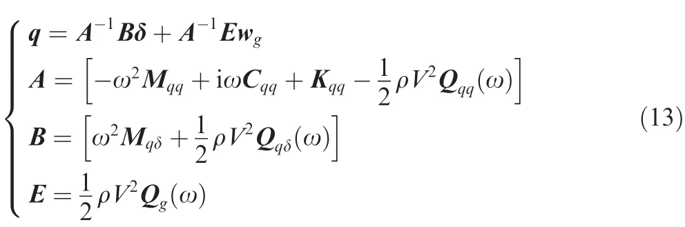
The frequency domain open-loop aeroelastic equation of motion in the generalized coordinates,excited by control surfaces motion and atmospheric gusts,is expressed as22

The left-hand-side matrix coef ficient matrices are the generalized mass matrix Mqq,the damping matrix Cqq,the stiffness matrix Kqq,and the aerodynamic in fluence coef ficients(AIC)matrix Qqqassociated with the modal displacements q.The right-hand-side matrices are the generalized mass matrix Mqδand the AIC matrix Qqδdue to de flection of control surface δ.The AIC matrix Qgis connected to gust velocity vector wg.After solving the equation,the modal displacement q can be expressed as follows:23
Assuming that the wing-tip acceleration isny,it can be written as

wheref1isthemodaldisplacementarrayofwing-tip accelerometer.The relation between control surface commanded de flections δ and aircraft’s motion signalnyis

where T is the GLA feedback loop transfer function.Considering Eqs.(14)and(15),the modal displacements in Eq.(13)can be written as a function of wg:

Assuming the acceleration of a certain point on the aircraft isa,which can be expressed as

where fsris the modal displacement array of this point.So Eq.(17)is the transfer function from the input gust excitation to the acceleration of a certain point.Also,for a finite element structural model,we can get the transfer function from the input gust excitation to the internal stress of a certain element:

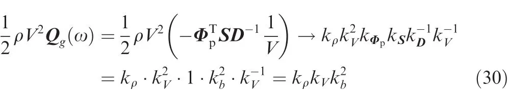
and Ksris the stiffness matrix of this element.For the convenience of the following deducing,the wing tip acceleration is chosen as the output and the transfer functionG(ω)can be de fined as

The relationship or the scaling criterion of GLA control system can be expressed as the following form:

whereG(ω)is the transfer function of the full-scale model,andthe transfer function of the scaled model.=ωkω.The following deducing studies the response of wing tip acceleration as expressed in Eq.(19).According to the general similarity criterion,the terms in the equation:A,B,E,f1,fsrhave been determined once the physical parameters are scaled.So the only term that needs to be specially designed or scaled is the GLA feedback loop transfer function T.
Before studying the scaling factors,the modal matrix Φ should be normalized first.The method used here is normalizing the first term of eigenvectors,which means φj1=1.

With the normalization above and adopting the double lattice method(DLM)for aerodynamic forces,24some precondition can be given for the deduction:
(1)Except for the control surfaces,the modal array of a point on the scaled model is the same as the modal array of the corresponding point on full-scale aircraft,which also means on corresponding panels,Φp(modal matrix of aerodynamic center)and Φq(modal matrix of control point)satisfy the equation:kΦp=kΦq=1.And modal arrays such as fsrand f1have the relationship kf1=kfsr=1.
(2)For the de flection modal matrix of control surfaces,the relationship would be different.The length scaling is taken into consideration for the reason that the distance from a point on control surface to the hinge has been scaled by kb.Consequently the relationship of de flection modal matrix can be written as kΦδ=kb.
(3)The aerodynamic in fluence matrix D of both models are the same if the panels for DLM are in similar shapes,which means kD=1.
(4)If Froude number is matched,some basic scaling relationscan be obtained from Eq.(9)and Table 2.

Neglecting the damping matrix Cqqand using the basic scaling relations:each term’s scaling relation can be written.The first term of A is

It is obvious that all the terms are of the same scaling ratio,and then A’s ratio of the scaled model to the full-scale model can be written as

For terms of B,the scaling relation can also be written in the same way.The first term of B is
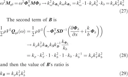
Finally,E has only one term and the scaling relation can be written as
then the value of E’s ratio is

With the A,B,E’s ratios being obtained above and the basic relations(Froude number similarity),kf1=kfsr=1,the transfer function ratio of the scaled model to the full-scale model can be expressed as

To satisfy the similar control systems’criterion as provided in Eq.(20),the GLA feedback loop transfer function ratiokTmust be equal to 1.Only in this way could thekGin Eq.(32)be a constant.And ifkT=1,it also means that the GLA feedback loop transfer function of the scaled modeland the transfer function T(ω)of the full-scale model have the relation
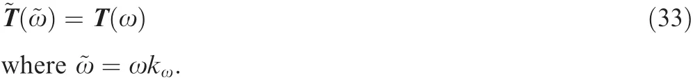
However,in case Froude number was not matched,the transfer function ratio of the scaled model to the full-scale model could be expressed as

Also to satisfy the similar control systems’criterion as provided in Eq.(20),the GLA feedback loop transfer function ratiokTmust be equal toOnly in this way,could thekGin Eq.(34)be a constant.And ifit also means that the GLA feedback loop transfer function of the scaled modeland the transfer function T(ω)of the full-scale model have the relation:

So when scaling GLA control system,Eqs.(33)and(35)are the goal to achieve.Eventually,both the scaling criterion and the scaling method of GLA control system have been provided as those in Eqs.(20),(33)and(35).
3.Numerical veri fication
To verify the scaling laws of the GLA control system,a fullscale airplane with GLA control system is chosen as the numerical example.By using the scaling methodology above,two scaled models are constructed with the same length parameter but different airspeed parameters,as the Froude number of scaled model 1 is matched while this nondimensional parameter is not matched in scaled model 2.Both two scaled models are of great importance:scaled model 1 represents the GLA wind tunnel test in which gravity plays an important role and scaled model 2 gives us a way to check the in fluence of the non-existence of Froude number similarity.
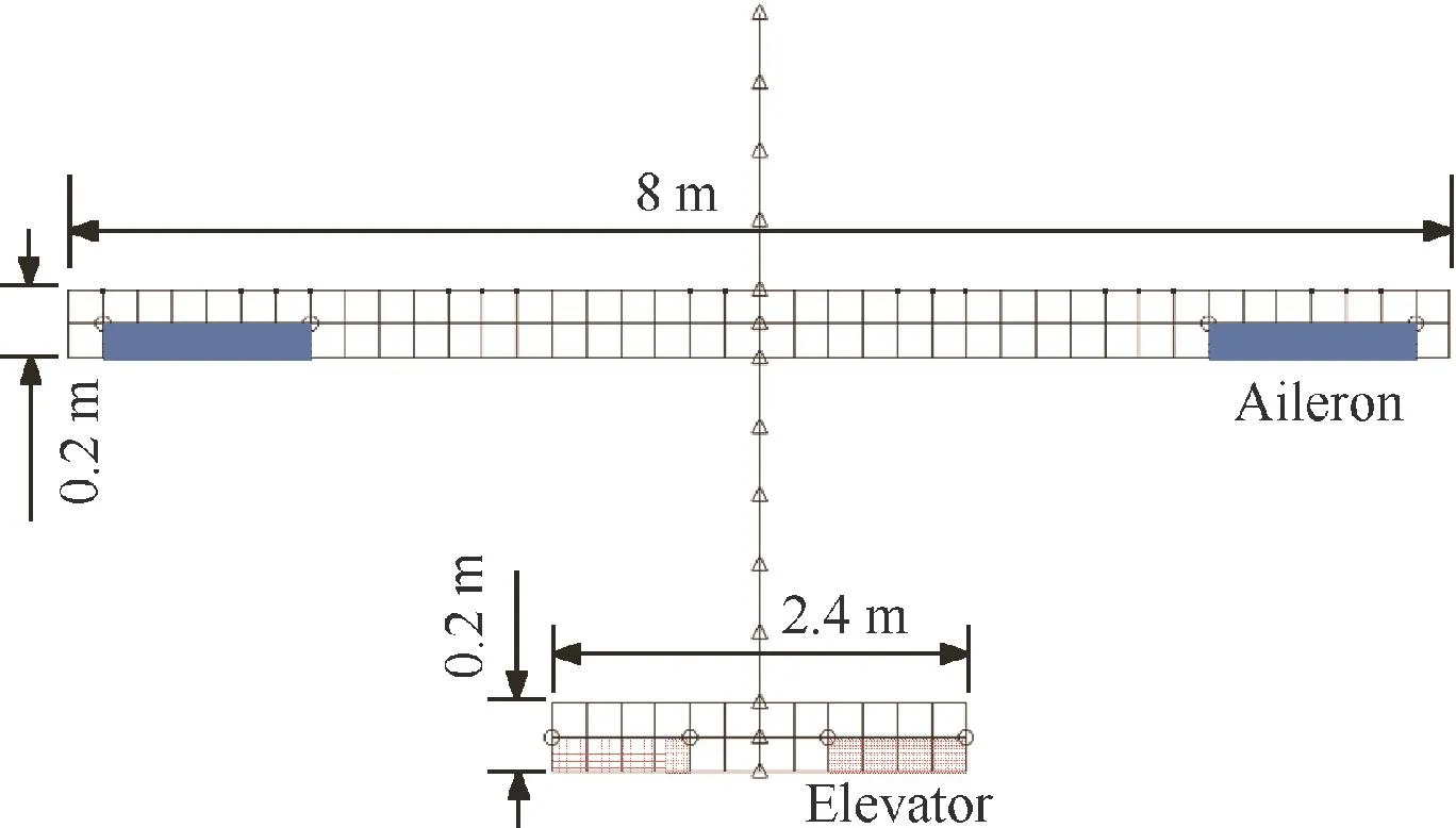
Fig.2 Finite element model of full-scale aircraft.
By comparing the gust responses of the models in openloop and closed-loop condition,the scaling criterion and methodology are validated.
3.1.Model description
The finite element model of the full-scale airplane is described by some basic geometrical parameters as shown in Fig.2.As only the longitudinal characteristics are considered in this paper,the lateral characteristics are neglected and there is no vertical fin or rudder in this model.The elevator is used for trimming and the aileron is adopted as control surface for GLA.
3.1.1.Common parameters for full-scale model and scaled model
Table 3 has provided some parameters for the full-scale model and the scaled models.There are only two independent scaling factors in scaled model 1:air density ratiokρ=1 and length ratiokb=1/10,as the Froude number has been matched and thus airspeed ratiokVbecomes a dependent parameter.However,the scaled model 2 has three basic independent scaling factors as the Froude number is not matched.For all these three models,the airspeed is low enough to ignore the Mach number similarity.In addition,the Reynolds numbers are considered to be on the same order of magnitude.3.1.2.GLA feedback loop description for full-scale model and scaled models
The scaled models studied here not only satisfy the general criteria,but also is engaged with a scaled GLA control system.The GLA feedback loop includes 3 major units:sensor,control law and actuator.The feedback mechanism is described as follows:the acceleration signal is measured by the sensor,after processed by the low pass filter and the designed control law,the signal becomes the actuator de flection command,which actuate the control surface to alleviate the gust load.
The low pass filter unit can be expressed as a 1st-order transfer function,while the actuator model is considered as a 3rd-order transfer function.As shown in Table 4,all the units in the feedback loop are scaled by applying the method shown in Section 2.2.2.As we can see,the GLA transfer function of scaled model 1 and scaled model 2 are different as the scaled model 2 frees the restraint betweenkVandkb.
3.2.Comparison of general aeroelastic analysis results
The following comparisons focus on some general aeroelastic characteristics.These aeroelastic similarities can be achieved by satisfying the general scaling laws.
3.2.1.Aeroelastic trim analysis
After general aeroelastic scaling,the similarities of aerodynamic shape,stiffness distributions and mass distributions ensure the similarity of static aeroelastic response.But there are also some distinctions between these three models as Froude number is not matched in scaled model 2.
In the aeroelastic trim analysis,the angle of attack and the de flection of the elevator are compared.The load factor is held as a constant at 1 for the two models.And for the full-scale model,the airspeed varies among 35 m/s,40 m/s,and 45 m/s,so correspondently for the scaled model 1,the airspeed variesscaled model 2,the airspeed scaling factor is freed and the velocities are chosen among 8.75 m/s,10 m/s,and 11.25 m/s.

Table 3 Geometric properties,air and scaling parameters for full-scale,scaled model 1(Froude number matched)and scaled model 2(Froude number not matched).

Table 4 Transfer functions of GLA feedback loop units.
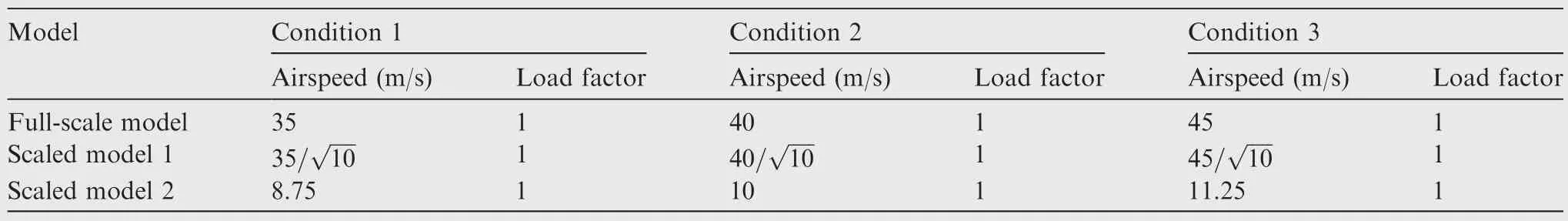
Table 5 Condition for aeroelastic trim analysis.

Fig.3 Comparison of aeroelastic trim results.
The conditions for aeroelastic trim analysis is given in Table 5 and the comparisons of the aeroelastic trim results are shown in Fig.3.It should be noted that for the convenience of comparison in one figure,the airspeeds of the scaled models have been factored to match the airspeed of the full-scale model.As shown in Fig.3,the angle of attack and the de flection of the elevator are consistent under different conditions for full size model and scaled model 1.But as the gravity provides one of the loads in trim analysis and Froude number is quite important here,scaled model 2 cannot share the same result with full size model and scaled model 1 as expected.
3.2.2.Mode analysis
Mode analysis is the basis of dynamic aeroelastic analysis.Table 6 shows the natural frequencies of some major symmetric modes,as the anti-symmetric modes being removed.The mode analysis results show that not only the natural mode
shapes are similar,but also the ratios of frequencies are consistent.All the frequencies’ratios here satisfy the basic relation:

3.3.Comparison of GLA analysis results
The results of GLA analysis are discussed in this section.The excitation used here is a discrete vertical gust as shown in Fig.4.The GLA analysis is based on similar GLA control systems.It should be noted that the gust excitations should also be similar in gust response analysis.The GLA control system has been described before;the flight and gust parameters are listed in Table 7.The scaling factors of maximum gust velocity and gust wavelength are the same askVandkb.
Gust responses are calculated on the full-scale model and the scaled models under both open-loop and closed-loop conditions.For the convenience of comparison,the time of thethese responses has been converted into non-dimensional time using the equation τ=Vt/b.

Table 6 Comparison of natural frequencies.

Fig.4 ‘1-cosin’type gust excitation.
The results of wing tip acceleration have been shown in Fig.5(a).As the open-loop condition means that there is no GLA control system working,the similarity of response under open-loop condition can be achieved by just satisfying the general scaling criteria.As illustrated in Eq.(11),if the Froude number were matched,the scaled model would get the same acceleration results with full size model,which is veri fied by scaled model 1 and full size model in Fig.5(a).However,without the Froude number similarity,the acceleration response of scaled model 2 can still re flect the open-loop response of fullscale model by multiplying the result by 1/ka.This suits a more common case that the Froude number is not matched and has been expected from Eq.(11).So generally speaking,the wing tip acceleration responses under open-loop condition of the three models are in great consistence.
The closed-loop condition means that the GLA control system comes into work.The wing tip acceleration signal has been measured and delivered to control system to create the alleviation command.As shown in Fig.5(b),the wing tip acceleration hasbeen alleviated signi ficantly compared to the response under the open-loop condition in Fig.5(a).The important thing is,the response curve of the scaled model 1 fits in well with the response curve of the full-scale model under the closed-loop conditions,which veri fies the correctness of the GLA scaling methodology.Also by amplifying the closed-loop acceleration 1/katimes,the response curve of scaled model 2 could fit in well with the response curve of the full-scale model as shown in Fig.5(b).This means scaled model 2 could also represent the alleviation result of full size model with some data processing.
In addition,the bending moment and shear force responses due to gust have been given in Figs.6 and 7.To compare conveniently,the bending moment and shear force responses of scaled models are ampli fied 1/kMEand 1/kFStimes respectively according to Eq.(10).Apparently under both open-loop and closed-loop conditions,the internal force(bending moment and shear force)responses of scaled model and full-scale model are consistent in non-dimensional time.
Actually,the GLA control system scaling methodology used here is deduced from the transfer function of wing tip acceleration but not the internal force.It comes out that the internal force responses are scaled correspondingly.So the analysis results have veri fied the scaling criterion and scaling method of GLA control system in more than one way.The analysis of scaled model 2 is quite important here since it demonstrates that the non-existence of Froude number similarity could also get acceptable results,but this conclusion can only be suitable when gravity is an unimportant factor for full size model and could be evaded by some measurements in wind tunnel tests.
4.Results and discussion
The numerical analysis above proves the correctness of the scaling criterion and method derived from the Eq.(12).But there are still some dif ficulties in practical application.For one thing,we may not get the ideal actuator or sensor which just has the same transfer function as the theoretical scaledone.For another,the scaling method studied above mainly deals with linear systems,but there are saturations in actuator that cannot be considered as linear units for simplicity.So how to scale the rate and amplitude saturation in actuator remains a signi ficant problem yet to be resolved.The discussion below gives satisfying solutions and has been veri fied by numerical simulation.

Table 7 Flight parameters and gust parameters for full-scale and scaled models.
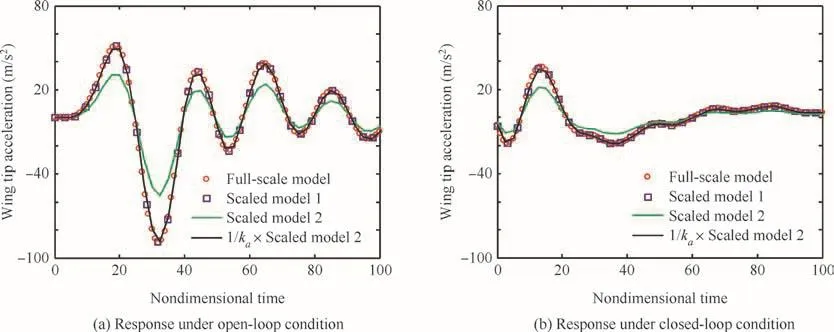
Fig.5 Wing tip acceleration response due to discrete gust.

Fig.6 Bending moment response due to discrete gust.
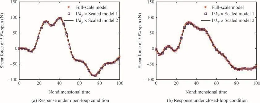
Fig.7 Shear force response due to discrete gust.
4.1.Transfer function compensating method
If the theoretical scaled actuator were not available in real situation,compensating measures could be taken in the forehead GLA control law.As shown in Fig.8,assuming that the transfer function of actuator that can be obtained isH3(s),then after compensating,the GLA control law will beH2(s):
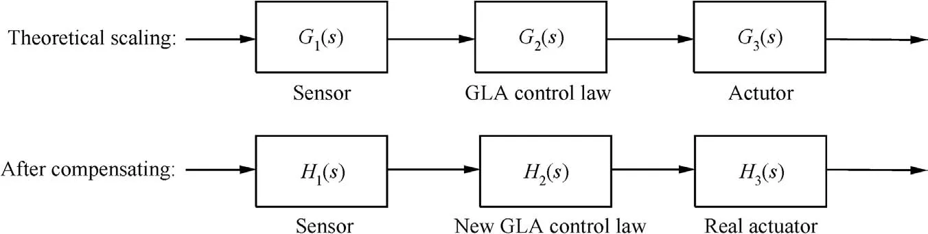
Fig.8 Method to compensate non-ideal actuator.

Although there are some changes in the transfer function of control law and actuator,the whole transfer function will stay unchanged,which will consequently make no difference in the alleviation result.And this solution can also be adopted in the situation that the theoretical sensor cannot be obtained.
4.2.Scaling laws of saturation in actuator
Considering the actuator as a second-order control system and the Simulink model is shown in Fig.9(a),the input of the actuator is the de flection command and the output is the de flection angle of control surface.During the GLA process,it is possible that the actuator reaches its maximum rate or amplitude in either direction,which means the rate or amplitude saturation comes into work.Saturations are non-linear units and should be specially treated in the scaling process.The ranges of rate and amplitude saturations in scaled actuator model remain unknown and are underlined in Fig.9(b).
To get a better understanding of the problem,some research has been conducted in the situation that the actuator works in an appropriate range without the saturation working,thus the unknown range of saturation will not affect the results.By observing the amplitude and rate responses of full-scale actuator in GLA process shown in Fig.10,it is apparent that the amplitude value of a certain timetis actually the area value surrounded by the rate curve and the axis before the timet.And this is identical to the mathematical meaning of the integration units in Fig.9(a).In Fig.11,the response of scaled actuator shows the similar relationship between rate curve and amplitude curve,with a difference that the area must be multiplied bykωas a scaling effect of integration units in Fig.9(b).Eventually,the pattern of responses at corresponding timet(full-scale model)and(scaled model)has been obtained;the amplitude and rate of full-scale and scaled actuator satisfy the following form:

Fig.9 Full-scale and theoretical scaled actuator models with the scaled saturation range undetermined.

Fig.10 Response of full-scale actuator with saturation units not working.

Fig.11 Response of scaled actuator with saturation units not working.

wheref(t),)are the rate responses;δ(t),)are the amplitude responses for the full-scale actuator and the scaled actuator respectively.The corresponding time above means that=ktt=Note that this is the situation when the saturations do not work.
Inspired by the above response pattern of no saturation working,an idea has come up that after the scaling of saturation units,there should be a same consequence on amplitude and rate responses as Eq.(38)has revealed.This is taken as a scaling request in the following deduction.
To study the scaling method of actuator saturation,hypothetical rate curves are drawn in Fig.12,and the saturation effects are simpli fied as the red dotted line.For full-scale actuator,the range of rate saturation is-A-+A(known).And for scaled actuator,the range of rate saturation is-B-+B(unknown).In addition,the rate responses of full-scale actuator and scaled actuator have the relationship:f(t)=at corresponding time.All these assumptions are the prerequisites for the deducing below.
Considering that the red line is taking effect,the actuator amplitude responses of the full-scale actuator and scaled actuator can be written by the following form:
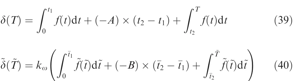
where timeTis betweent2andt3;is betweenandfor simplicity.
If we makeA=B,then there will be=and=because of the relationship of rate response:f(t)=~f(~t).Consequently the 3 terms on the right hand side of Eq.(40)can be replaced by the following forms:

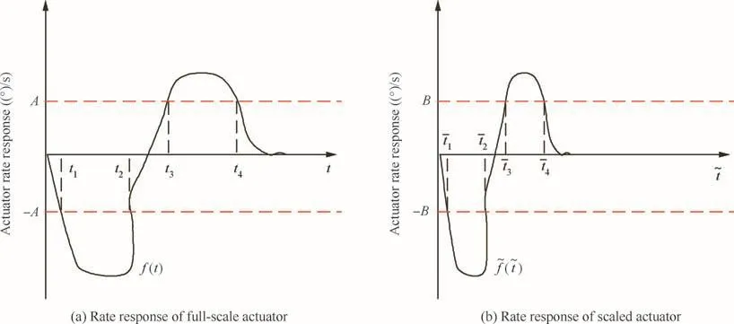
Fig.12 Hypothetical rate responses of full-scale and scaled actuators.
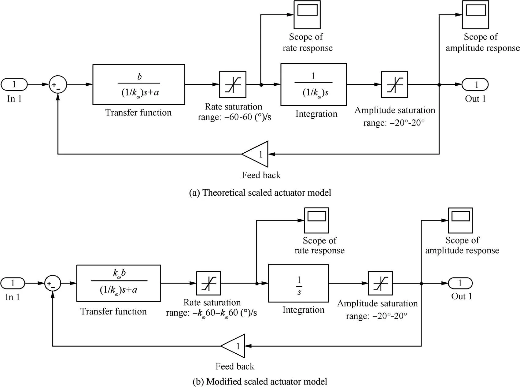
Fig.13 Theoretical and modi fied scaled actuator models with scaled saturation range determined.

and then Eq.(38)is perfectly satis fied:

This solution can also be adapted to the situation thatTis not betweent2andt3.So theoretically,the range of rate saturation for the scaled model should be the same as the range of rate saturation for the full-scale model.And the same scaling laws can be applied to the scaling of amplitude saturation.

Fig.14 MATLAB simulation scheme of GLA process.

Fig.15 Response of full-scale actuator with saturation units working.

Fig.16 Response of scaled actuator with saturation units working.
However,there is still a problem that we should pay attention to.Because of its real physical meaning,the integration unit cannot be simply scaled fromas shown in Fig.13(a).The integration unit should stay aseven in the scaled actuator.So with the scaling solution of saturation above and the unchanged request of integration unit,we eventually get the modi fied scaled actuator model as shown in Fig.13(b).The location ofkωis shifted forward and thus making the range of saturation ampli fiedkωtimes as underlined in Fig.13,also the transfer function before rate saturation is multiplied bykω.

Fig.17 Load factor responses in absolute time.
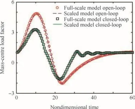
Fig.18 Load factor responses in non-dimensional time.
To verify the scaling method of saturation units,a simple numerical simulation has been conducted and the Simulink model is shown in Fig.14,using the load factor as the feedback signal for GLA.In an equilibrium state the load factor equals to 1.0,therefore the real control signal should be the offset from 1.0 as shown in Fig.14.
The actuator units in the Simulink can be referenced in Figs.9(a)and 13(b)for the full-scale and the scaled size.In this case,the gust excitation is adequate enough to make the saturation units come into work,which is different from the situation discussed in Figs.10 and 11.
The result gives a suf ficient support to the scaling method derived in this section.The rate and amplitude responses of this simulation are plotted in Figs.15 and 16,and apparently Eqs.(37)and(38)are completely satis fied.The goal of this simulation is to alleviate the load factor of mass center.In Figs.17 and 18,the load factor responses are shown in absolute time and non-dimensional time respectively.Not only the open-loop responses but also the closed-loop responses are in consistence,which proves that the scaling laws of actuator saturation units are truly effective.
5.Concluding remarks
Scaling laws for GLA tests are studied in this paper,mainly concentrating on the scaling criterion and method of GLA control system.The object investigated is a general airplane with gust load alleviation control system and the excitation used here is a ‘1-cosin’type gust.Also,taking the practical factors into consideration,some viable methods have been brought up for real situation.And findings of this study are summarized below.
(1)Based on whether the GLA control system comes to work,the gust response of aircraft can be sorted into two types:the open-loop response and the closed-loop response.The open-loop responses of the scaled model and the full-scale model can be aeroelastically similar by simply adopting the general aeroelastic scaling laws.However,the similarity of closed-loop response requires the scaling of GLA control systems.For a GLA control system based on classical PID control theory,the scaling criterion can be represented as the relationship of similar transfer functions.The scaling method can be derived from the scaling criterion and is veri fied by numerical analysis in this paper.It would be useful in GLA test if the scaling criterion and method studied above were adopted in scaling the GLA control systems.The method to obtain the scaling criterion and methodology in this paper also provides a helpful route when scaling GLA control systems based on other control theories.
(2)Froude number similarity could be quite important if the gravity provides one of the signi ficant loads.But there is similarity that could be evaded if the gravity were relatively a quite unimportant factor for full size model and GLA test model could be mounted on the floor rather than on the wall to avoid the effect.In this situation,the GLA scaling laws studied in this paper could still ensure the similarity of both open-loop and closed-loop acceleration response and internal force response.This conclusion would help a lot in practical application as it frees restraint between airspeed scaling factor and length scaling factor,thus make the whole scaling work more flexible.However,in many practical cases the gravity is actually an important factor in gust related tests which needs to be speci fically concerned,so it is often recommended to match the Froude number in gust related scaling work.
(3)When building the scaled control system for practical use,the sensor or the actuator that can be obtained might not fit well with the theoretical scaled ones.In this situation,a compensating method has been come up by changing the transfer function of control law.Usually,there are rate and amplitude saturations in actuators.They are non-linear units in control systems and need some special consideration when scaling.To deal with this,a viable scaling approach has been provided and veri fied by numerical simulation.
This study was supported by the National Natural Science Foundation of China(Nos.11372023 and 11402013).
1.Hobilit FM.Gust loads on aircraft:concepts and applications.Washington,D.C.:AIAA Education Series;1998.p.15–69.
2.Jin CJ,Xiao YL.Flight principles in atmosphere turbulence.Beijing:NationalDefense IndustryPress;1992.p.11–48,[Chinese].
3.Shao K,Wu ZG,Yang C,Chen L,Lv B.Design of an adaptive gust response alleviation control system:simulations and experiments.J Aircraft2010;47(3):1022–9.
4.Dillsaver MJ,Cesnik CES,Kolmanovsky IV.Gust load alleviation control for very flexible aircraft.Reston:AIAA;2011.Report No.:AIAA-2011-6368.
5.McLean D.Gust load alleviation control systems for aircraft.IET1978;125(7):675–85.
6.Aouf N,Boulet B,Botez R.H2 and H-in finity optimal gust load alleviation for a flexible aircraft.Proceedings of the American control conference.Piscataway,NJ:IEEE Press;2000.p.1872–6.
7.Shao K,Yang C,Wu ZG,Liu H,Wen BL.Design of a gust response alleviation online control system based on neuro-fuzzy theory.J Aircraft2013;50(2):599–609.
8.Vartio EJ,Shaw EE.Vetter T.Gust load alleviation flight control system design for a SensorCraft vehicle.Reston:AIAA;2008.Report No.:AIAA-2008-7192.
9.Penning KB,Scott Zink P,Wei P,De La Garza AP,Love MH.GLA and flutter suppression for a SensorCraft class concept using system identi fication.Reston:AIAA;2008.Report No.:AIAA-2008-7188.
10.Ricci S,Scotti A.Wind tunnel testing of an active controlled wing under gust excitation.Reston:AIAA;2008.Report No.:AIAA-2008-1727.
11.Wu ZG,Chen L,Yang C.Study on gust alleviation control and wind tunnel test.Sci China Ser E2013;56(4):762–71[Chinese].
12.Shao K,Wu ZG,Yang C,Chen L.Theoretical and experimental study of gust response alleviation using neuro-fuzzy control law for a flexible wing model.Chin J Aeronaut2010;23(3):290–7.
13.Wan ZQ,Cesnik CES.Geometrically nonlinear aeroelastic scaling for very flexible aircraft.Reston:AIAA;2013.Report No.:AIAA-2013-1894.
14.Bisplinghoff RL,Ashley H.Principles of aeroelasticity.New York:Dovers Publications;1996.p.698–715.
15.Friedman PP.Adaptive control of aeroelastic instabilities in transonic flow and its scaling.Reston:AIAA;1997.Report No.:AIAA-1997-0581.
16.Friedman PP.Aeroelastic scaling for fixed and rotary-wing aircraft with applications.Reston:AIAA;2000.Report No.:AIAA-2000-1688.
17.Pototzky AS.Scaling laws applied to a modal formulation of the aeroservoelastic equations.Reston:AIAA;2002.Report No.:AIAA-2002-1598.
18.Pereira P,Almeida L,Suleman A,Can field R,Bond V,Blair M.Aeroelastic scaling and optimization of a joined-wing aircaft.Reston:AIAA;2007.Report No.:AIAA-2007-1889.
19.Guan D.Aeroelastic test.1st ed.Beijing:Beihang University Press;1986.p.78–83[Chinese].
20.Scott RC,Vetter TK,Penning KB,Coulson DA,Heeg J.Aeroservoelastic testing of a sidewall mounted free flying windtunnel model.Reston:AIAA;2008.Report No.:AIAA-2008-7186.
21.Sharma V,Reichenbach R.Development of an innovative support system for SensorCraft model.Reston:AIAA;2011.Report No.:AIAA-2011-1958.
22.Moulin B,Karpel M.Gust loads alleviation using special control surfaces.J Aircraft2007;44(1):17–25.
23.Chen L,Wu ZG,Yang C,Tang CH,Wang LB.Gust response,load alleviation and wind-tunnel experiment veri fication of elastic wing.Eng Mech2011;28(6):212–8[Chinese].
24.Albino E,Rodden WP.A double-lattice method for calculating lift distributions on oscillating surfaces in subsonic flows.AIAA J1969;7(2):279–85.
杂志排行

CHINESE JOURNAL OF AERONAUTICS的其它文章
- Plastic wrinkling prediction in thin-walled part forming process:A review
- Progress of continuously rotating detonation engines
- Microstructure control techniques in primary hot working of titanium alloy bars:A review
- A hybrid original approach for prediction of the aerodynamic coefficients of an ATR-42 scaled wing model
- Dynamic modeling and analysis of vortex filament motion using a novel curve- fitting method
- Boundary-layer transition prediction using a simpli fied correlation-based model