Numerical simulation of the abrasive supercritical carbon dioxide jet:The flow field and the influencing factors*
2016-10-14ZhenguoHE贺振国GenshengLI李根生HaizhuWANG王海柱ZhonghouSHEN沈忠厚ShoucengTIAN田守嶒PeiqingLU陆沛青BinGUO郭斌
Zhen-guo HE (贺振国),Gen-sheng LI (李根生),Hai-zhu WANG (王海柱),Zhong-hou SHEN (沈忠厚),Shou-ceng TIAN (田守嶒),Pei-qing LU (陆沛青),Bin GUO (郭斌)
1.State Key Laboratory of Petroleum Resources and Prospecting,China University of Petroleum (Beijing),Beijing 102249,China,E-mail:anonymous_id@foxmail.com
2.PetroChina Tarim Company,Korla 841000,China
Numerical simulation of the abrasive supercritical carbon dioxide jet:The flow field and the influencing factors*
Zhen-guo HE (贺振国)1,Gen-sheng LI (李根生)1,Hai-zhu WANG (王海柱)1,Zhong-hou SHEN (沈忠厚)1,Shou-ceng TIAN (田守嶒)1,Pei-qing LU (陆沛青)1,Bin GUO (郭斌)2
1.State Key Laboratory of Petroleum Resources and Prospecting,China University of Petroleum (Beijing),Beijing 102249,China,E-mail:anonymous_id@foxmail.com
2.PetroChina Tarim Company,Korla 841000,China
The supercritical carbon dioxide (SC-CO2) jet can break rocks at higher penetration rates and lower threshold pressures than the water jet.The abrasive SC-CO2jet,formed by adding solid particles into the SC-CO2jet,is expected to achieve higher operation efficiency in eroding hard rocks and cutting metals.With the computational fluid dynamics numerical simulation method,the characteristics of the flow field of the abrasive SC-CO2jet are analyzed,as well as the main influencing factors.Results show that the two-phase axial velocities of the abrasive SC-CO2jet is much higher than those of the abrasive water jet,when the pressure difference across the jet nozzle is held constant at 20 MPa,the optimal standoff distance for the largest particle impact velocity is approximately 5 times of the jet nozzle diameter; the fluid temperature and the volume concentration of the abrasive particles have modest influences on the two-phase velocities,the ambient pressure has a negligible influence when the pressure difference is held constant.Therefore the abrasive SC-CO2jet is expected to assure more effective erosion and cutting performance.This work can provide guidance for subsequent lab experiments and promote practical applications.
abrasive supercritical carbon dioxide jet,numerical simulation,velocity distribution,impact factor
Introduction
Nowadays,the shale gas development is in full swing in China with a considerable output.However,the lavish cost of the well drilling and the simulations in the shale gas fields still constrains the economic benefit and further development of the shale gas industry in China.Therefore,new techniques instead of the use of water-based fluids are in great demands to achieve a higher yield with a lower cost.Since 2000,a great deal of theoretical and experimental studies concerning the rock-breaking process and the feasibility of well drilling using the supercritical carbondioxide (SC-CO2) jet have been conducted in the USA[1],as well as in China in recent years[2,3].The SC-CO2fluid has unique properties such as no permeability damage caused from the water lock,rapid clean up and reduced proppant flowback during the hydraulic fracturing.Similar to the abrasive water jet,the abrasive SC-CO2jet is formed by adding solid particles into the SC-CO2jet.It might achieve a better jet perforation,by combining the technical advantages of the SC-CO2jet like the high velocity and the high hydrostatic pressure transmission capacity,and of the abrasive jet like the fine cutting performance on metal and hard materials.
The abrasive water jet technique is now in a matured stage and is applied into many fields like the well drilling,the hydraulic fracturing,the mining,the metallurgy,and the military industry[4,5].Meanwhile,the micro abrasive air jet (MAAJ) machining techniques have been studied in China and utilized in the rust removal,the polishing,the micro powder manufacturing and other fields[6,7].Successful applications of the MAAJ indicate the promising prospects of the abrasive SC-CO2jet due to the low viscosity and thesatisfactory particle-carrying capacity.
The SC-CO2fluid has a similar density as an ordinary liquid and a similar viscosity as the gas.Its surface tension is zero and the mass transfer capacity is excellent,very good for rock-breaking[8,9].The impact of the solid particles in the abrasive jet plays a much more important role in cutting than that of the fluid,therefore,there is a need to study and verify whether the particles in the abrasive SC-CO2jet can acquire a similarly high impact velocity to that of the particles in the abrasive water jet,combined with the good flow characteristics of the jet.To deal with this problem,based on the computational fluid dynamics,the flow field of the abrasive SC-CO2jet and the distributions of the two-phase velocities and pressure are obtained and compared with those of the abrasive water jet.The effects of several operating factors are revealed and the advantages of the abrasive SC-CO2jet over the abrasive water jet are preliminarily evaluated with respect to the cutting performance and the future applications in the shale gas development.
1.Modeling
1.1 Fundamental assumptions
This work is based mainly on the following fundamental assumptions:(1) the physical model will not be distorted in the simulations,(2) the solid particles are spheres of equal diameter,(3) no mass loss from the particles or the exchange between the particles and the fluid,(4) taking account of the forces which have a significant influence on the particle motion like the inertia force,the drag force and other forces in the direction of the particle motion,while ignoring the forces that have little influences like the Magnus force and the Saffman force,(5) at the initial stage,the SC-CO2fluid and the solid particles are the only two types of matter that are filled in the simulated computational domain.

Fig.1 Plane sketch of the geometrical model (m)
1.2 Geometrical model
The computational domain consists of the flow fields in and out of the jet nozzle,with two straight orifices on both sides and one contraction section in the middle.According to related lab experiments on the SC-CO2and field applications on the abrasive water jet,the nozzle structure and the solid particles are selected[10],as shown in Fig.1.The diameter of the nozzle outlet Φnis 0.006 m,the ratio of the length to the diameter of the front straight pipe is 2:1,the angle of the contraction is30.5o.The standoff distance from the jet nozzle to the impact walldjetand the distance from the investigated transverse section to the impact wallLwill be given different values for different investigation aims.
Due to the severe changes of the fluid velocity and properties,the mesh is refined in the nozzle and in the cone-shaped jet flow area with the boundary surface of Face 3 in Fig.2,to improve the calculation accuracy.The mesh volume of the whole computational domain is 484 956,76.6% of which are in the mesh refinement area.

Fig.2 Physical model of the computational domain (mesh refinement included)
Mesh convergence study shows that with the mesh model used in this research,stable simulation results are obtained[11].
1.3 Governing equations
Unlike the water,the SC-CO2fluid is compressible and sensitive to temperature and pressure[8].Span and Wagner[12]modified the calculation model for the CO2fluid via experiments and made it suitable for a large range of pressure and temperature.The Span-Wagner equation has significantly improved the calculation accuracy and is widely used in the research of CO2[13].In the Span-Wagner equation,the Helmholtz free energy is used to calculate the state parameters,and its dimensionless form is
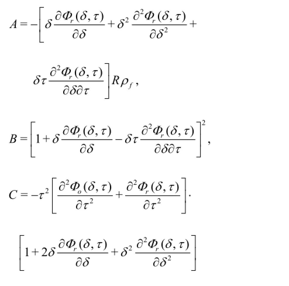
Then the compressibility factor,the specific heat capacity at a constant pressure and the coefficient of the Joule-Thomson effect are obtained as follows:

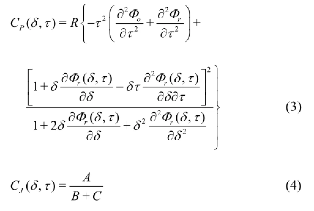
where
The Fenghour method and the Vesovic method are utilized,respectively,for calculating the viscosity and the heat conductivity coefficient as follows:

where ρfis the density of the fluid,and Tis the fluid temperature,τ is the viscous stress on the surface of the fluid element caused by the viscosity,Cpis the specific heat capacity of the fluid.
The flow of the SC-CO2jet follows the conservation laws,for the mass,the momentum and the energy.The derived continuity equation,the Navier-Stokes equation and the energy conservation equation for the three-dimensional steady compressible turbulent flow and the standard k -ε two-equation turbulent model are as follows[14]
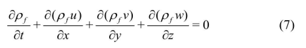
When calculating the flow field of an abrasive water jet,namely,an incompressible fluid,we have ∂ρf/∂t=0for the continuity equation,
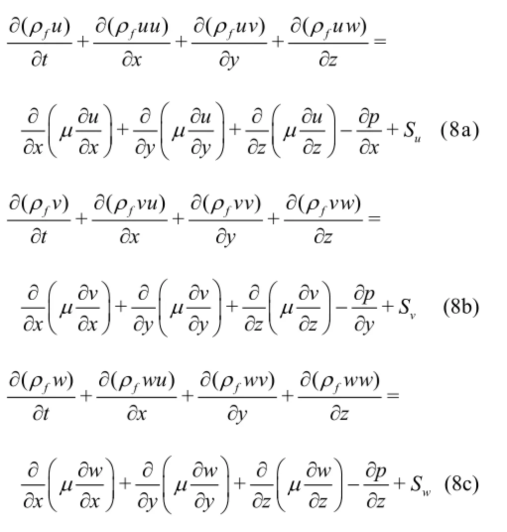
where u,v,ware the components of the velocity vectoruinx,y,zdirections,µis the dynamic viscosity.Su,Sv,Sware the generalized source term in the Navier-Stokes equation,
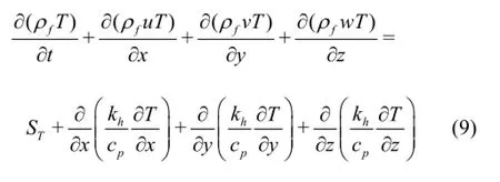
where the dissipation term of the viscosity ST,is the sum of the fluid internal heat source and the dissipation function (the conversion part from the mechanical energy to heat caused by the viscous effect),khis the heat transfer coefficient.For the abrasive water jet,the velocities and the pressure can be solved without the energy conservation equation because the heat exchange could be ignored,
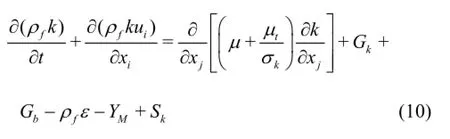
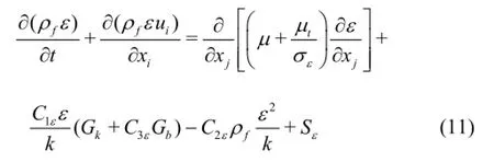
wherek is the turbulent kinetic energy,ε is the turbulent dissipation rate,uiis the time average velocity,µtis the turbulent viscosity,Gkis the derivative of the turbulent kinetic energyk caused by the average velocity gradient,Gbis the derivative of the turbulent kinetic energyk caused by the buoyancy,Prtis the Prandtl number,σkand σεare the corresponding Prandtl numbers for kand ε,YMis the contribution from the pulse expansion of the compressible turbulent flow.
For the flow field of the abrasive water jet,we have Gb=YM=Sk=Sε=0.
Based on the assumptions,the drag force,the inertial force,the Basset force are the main forces that are considered in the research.They have a major influence on the particle motion or the relative motion between the fluid and the solid particle.These forces acting on the particles are listed as follows[15-17]:
Drag force

Inertia force
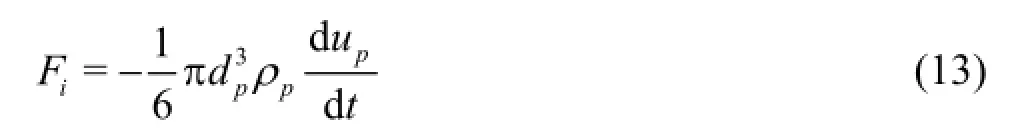
Pressure gradient force
Basset force

where CDis the drag coefficient and is related to the Reynolds number,ρpis the particle density,upis the particle velocity,ufis the jet fluid velocity and dpis the particle diameter.
1.4 Boundary conditions and solutions
According to the lab experiments and the field applications of the abrasive water jet,the boundary conditions are set as follows:
(1) The nozzle inlet (Face 1 in Fig.2) serves as the inlet of the geometrical model with the pressure inlet condition.The inlet pressure and the fluid temperature,when not as the investigated objects,are given constant values of 40 MPa and 353 K,respectively,the particle is given an initial axial velocity of 10 m/s,inlet pressure:pin=40 MPa,initial particle axial velocity:up0=10 m/s,initial radial velocity of fluid and particles:vf0=vp0=0.
(2) The annular face around jet nozzle exit (Face 2 in Fig.2) is defined as the outlet of the model with the pressure outlet condition.The ambient temperature pc,when not as the investigated object,is given a constant value of 20 MPa,and thus the pressure difference∆pis 20 MPa.
(3) The outlet of the nozzle and the boundary face of the mesh refinement domain (Face 3 in Fig.2)are both defined as under the interior condition.
(4) The rest of the faces in the model are defined as the stationary wall under the non-slipping and heatisolation conditions.
(5) The discrete phase model (DPM) is selected to simulate the motions of the abrasive particles.The numbers of the solid particles are chosen according to the lab experiments and the field operations for the abrasive water jet[18].The particles with a diameter of 0.0006 m and a density of 2.7×10³kg/m3are released from the inlet and enter the computational domain in the normal direction.The volume concentration η is 7.5% in the baseline calculations.
To reduce errors caused by the artificial viscosity term in the low-order discretization schemes,the second-order upwind scheme is chosen for a comparably high level of calculation accuracy and short calculation time[19].The SIMPLE method is used to solve the coupled equations of velocity and pressure,and it is shown to be stable by several numerical tests[14].Convergence criteria are:(1) the residuals of the iteration are less than 10-6,or (2) the difference of the mass flow between the inlet and the outlet is less than 0.5% of the inlet mass flow.
2.Results and discussions
Based on the research of the abrasive water jet and the MAAJ,the flow field of the abrasive SC-CO2jet is obtained and the main influencing factors are revealed.

Fig.3 Distributions of fluid velocities of abrasive SC-CO2jet and abrasive water jet
2.1 Analytical comparison with abrasive water jet
Numerical simulations of the abrasive SC-CO2jet and the abrasive water jet are carried out under the same pressure and temperature conditions.The inlet and outlet pressures are separately prescribed as 40 MPa and 20 MPa,the inlet and outlet temperatures are both set to 353 K,and the initial particle velocities in the two jets are both set to 10 m/s in the axial direction.The incompressible liquid water has a constant and larger density under the studied conditions.
The velocity distributions of the SC-CO2and the water are shown in Fig.3.It is seen that the acceleration process is similar.The velocity gradient varies drastically at the end of the contraction section and the fluids obtain the maximum velocity,respectively.The abrasive SC-CO2jet is shown to have advantages over the water jet such as:under the same conditions,the maximum axial velocity of the SC-CO2fluid is much higher than that of the water jet,the SC-CO2jet velocity is less attenuated due to a lower viscosity,the abrasive water jet has a stronger entrainment than the abrasive SC-CO2jet,the velocity gradient of the abrasive SC-CO2jet impacting on the wall is larger than that of the water jet.They indicate that the abrasive SC-CO2jet have a more focused and higher impact.
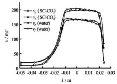
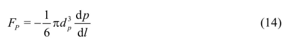
Fig.4 Axial distributions of two-phase velocities of two abrasive jets (pin=40 MPa,pc=20 MPa,Φn=0.006 m,Tin=353K,djet=0.024 m)
Figure 4 shows the velocity distributions of the fluid and the particles of the two jets along the center line,plotted as a function of the axial position.The nozzle outlet is located at the origin.The jet is parallel to the x-axis,from left to right.The graph directly shows the magnitude and the variation of the velocities across the nozzle.Under the same conditions(∆p=20 MPa,Tin=353K),the SC-CO2fluid obtains the maximum velocity up to 113.7% which is much higher than that of the water.
Moreover,it is seen that there is always a velocity difference between the fluid and the solid particles.The particle difference between the two phases shows the similar characteristics of the abrasive SC-CO2jet against the abrasive water jet in the jet nozzle.The fluid velocity attenuates out of the nozzle due to the frictional energy loss while the solid particles are still accelerated due to the drag force.The velocity difference is narrowed,until they impact on the wall at approximately equal velocities.

Fig.5 Distribution of axial velocity in the models with different standoff distances (pin=40 MPa,pc=20 MPa,Φn=0.006 m,Tin=353K,L=0.006 m)
2.2 Standoff distance
In the simulation,the standoff distance is set to 1,2,4,6,10 and 12.5 times of the nozzle diameter.The inlet and ambient pressures are set to 40 MPa and20 MPa,and the temperature is set to 353 K.
Figure 5 shows the radial distribution of the fluid axial velocity on different cross sections.The distances from the studied section to the impact wall are all set to 0.006 m in 6 geometrical models with different standoff distances.Similarly,Fig.6 shows the variations where the distances are all set to 0.003 m.Besides,the variation of the abrasive water jet velocity is also given in each graph for the analytical comparison.It is seen that the maximum velocity of the water jet is the least and the curve is the flattest.The phenomenon can be accounted for by the stronger entrainment effect of the water jet due to the high fluid viscosity and the associated frictional resistance.As the distance between the studied section and the impact wall is changed to 0.003 m,it is seen that depressions exist on the top of the curves.It indicates that the jet backflow obviously reduces the fluid impinging velocity and the pressure on the impact wall.

Fig.6 Distributions of axial velocity in the models with differrent standoff distances (pin=40 MPa,pc=20 MPa,Φn=0.006 m,Tin=353K,L =0.003m)

Fig.7 Distribution of jet impact pressure versus standoff distance (pin=40 MPa,pc=20 MPa,Φn=0.006 m)
Based on the fluid dynamics,the jet impact pressure under different studied conditions is calculated via Eq.(16).Figure 7 shows the variation of the jet impact pressure versus the standoff distance.The impact pressure first increases slightly and then decreases by a big margin as the standoff distance increases,the maximum impact is reached when the dimensionless standoff distance is approximately 4.As mentioned above,when the standoff distance is too short,the narrow space makes the jet fluid difficult to escape and the frictional resistance weakens the impact effect.While the distance is larger than the length of the jet potential core,the jet energy is reduced in the flow field,so is the fluid velocity.Hence,it may be said that there is an optimal standoff distance for the fluid to reach the peak value of the impact.

where Fjis the jet impact pressure,j is the angle between the jet flow direction and the impact wall.
Fig.8 Distributions of particle axial velocities at different positions in geometrical models with different standoff distances
The high velocity of the abrasive particle is necessary and critical for the abrasive jet impact and cutting.Therefore,the particle velocities in different models with different standoff distances are calculated.Figure 8 compares the particle velocity versus the standoff distance.In six models with the dimensionless standoff distance in the range from 1 to 12.5,the particle velocities in three axial positions are obtained.The curve in the lower block shows a monotone decrease of the particle velocity 0.003 m away from the impact wall as the standoff distance increases.The curve in the middle block shows the peak value of the particle velocity 0.001 m away from the impact wall.The largest velocity is reached when the dimensionless standoff distance is 4,indicating that the particles in the models with smaller standoff distances begin to experience a stronger resistance force from the backflow.The curve in the upper block illustrates the particle velocity at the positions where the distance to the impact wall is 0.0003 m.That is to say,these velocities are exactly the impact velocities on the wall because the particle radius is set to 0.0003 m.Therefore,an optimal dimensionless standoff distance of 5 will create the largest particle velocity and the best cutting effect.
Further simulations indicates that,when the pressure difference is between 10 MPa and 30 MPa,the optimal distance for the particle impinging velocity is in the range of 3-6 times of the jet nozzle diameter.Therefore,the standoff distance should be determined and optimized according to the working conditions to improve the operation performance.
2.3 Ambient pressure
The ambient pressure in the petroleum industry refers to the hydrostatic pressure at the bottom hole due to the weight of the operation fluids,on the objects such as the drilling bits and the operation fluids themselves.Generally,it has negative effects on the operation efficiency and is considered as one of main influencing factors.In this research,the back pressure on the outlet boundary is used to simulate the ambient pressure.The ambient pressure is sequentially set to 10 MPa,15 MPa,20 MPa,25 MPa and 30 MPa.The inlet pressure also varies to assure a constant pressure difference of 20MPa.The temperature is set to 353 K.The jet standoff distance is set to 4 times of the jet nozzle diameter.
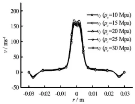
Fig.9 Distributions of jet fluid velocities versus ambient pressure (∆p=20 MPa,Φn=0.006 m,djet=0.024 m,L =0.003 m,Tin=353K)
The jet velocities as the function of the ambient pressure in two positions 0.003 m and 0.024 m away from the impact wall are shown in Figs.9 and 10.The jet velocity steadily and slightly decreases by 8.9% and 7.9% as the ambient pressure increases from 10 MPa to 30 MPa.The maximum particle velocity decreases from 208.0 m/s to 193.0 m/s,or by 7.2%,suggesting little influence of the ambient pressure on the two-phase velocities when the pressure difference is held constant.
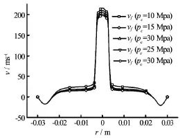
Fig.10 Distributions of jet fluid velocities versus ambient pressure (∆p=20 MPa,Φn=0.006 m,djet=0.024 m,L =0.024 m,Tin=353K)
Further simulations demonstrate the influence of the compressible SC-CO2density on the jet impact pressure,and it is shown that the velocity changes but little.Hence,when the abrasive SC-CO2jet is utilized in the perforation and cutting operations under downhole conditions,the performance will not be weakened substantially although the working depth increases.
2.4 Fluid temperature
The fluid density and viscosity can affect the particle-carrying capacity.Therefore,the fluid temperature is investigated and is sequentially set to 333 K,353 K,373 K,393 K,and 413 K.The inlet pressure and the ambient pressure are set to 40 MPa and
20 MPa.The jet standoff distance is set to 4 times of the jet nozzle diameter.
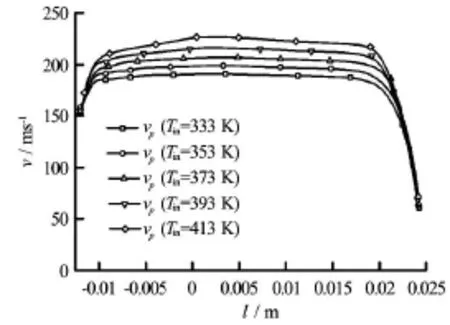
Fig.11 Distribution of particle axial velocity along the center line at different jet inlet temperatures (pin=40 MPa,pc=20 MPa,Φn=0.006 m,djet=0.024 m)
Figure 11 shows that the temperature rise causes a modest increase of the two-phase velocities.To be specific,as the fluid temperature rises from 333 K to 413 K,the maximum fluid velocity increases from 196.1 m/s to 235.5 m/s,or by approximately 20.1%,and the maximum particle velocity increases from 191.5 m/s to 228.0 m/s,or by approximately 19.1%.The velocity difference indicates a satisfactory particle-carrying capacity of the SC-CO2.The fluid temperature has a negligible influence on the velocity and the particle acceleration process.That is to say,the abrasive SC-CO2jet has a wide range of working temperature and depth.
Figure 12 presents the variation of the jet impact pressure as the function of the fluid temperature.The impact pressure is weakened as the temperature and the two-phase axial velocities both increase.Data show that the impact pressure reduces from 1367.3 N to 1063.4 N,or by approximately 22.2%,as the temperature rises from 333 K to 413 K.As a result,the effects of the transmitting fluid static pressure and the breaking rock matrix are weakened.

Fig.12 Distribution of jet impact pressure versus jet inlet temperature (pin=40 MPa,pc=20 MPa,To= 373 K,Φn=0.006 m,djet=0.024 m)
Further simulations demonstrate that the rising fluid temperature leads to a decrease of the density and the viscosity,and thus an increase of the velocity.The impact pressure is weakened because the decreased density has a stronger negative influence than a positive influence from the increased velocity.However,for the abrasive jet which relies mainly on the impact of the solid particles,the increased particle velocity improves the performance and the efficiency as the temperature rises.
2.5 Volume concentration of solid particles
The applications of the abrasive water jet see the best performance when the volume concentration is in the range of 5.0%-10.0%[10].The volume concentrations are thus sequentially set to 3.0%,7.5%,and 11.0%.The inlet pressure and the ambient pressure are set to 40 MPa and 20 MPa,respectively.The temperature is set to 353 K.The jet standoff distance is set to 10 times of the jet nozzle diameter so that the jet flow is fully developed.
Figure 13 shows the decreases of the two-phase velocities as the particle volume concentration rises from 3.0% to 11.0% in the two-step simulations.It is seen that the maximum fluid velocity decreases by 8.2% and 7.9%,and the maximum particle velocity decreases by 8.9% and 8.3%.The preliminary analysis shows that the mass flow rate increases and the kinetic energy for each particle is reduced.It is necessary to carry out further researches for the inter-particle interactions under different concentrations,to determine an optimal range of the concentration for the abrasive SC-CO2jet.

Fig.13 Distributions of fluid axial velocities and particles in different concentrations of discrete phase
Comparison shows that the two-phase velocities of the abrasive SC-CO2jet are higher when the volume concentrations of solid particle are equal,suggesting that it can achieve a higher working efficiency in field applications.
3.Conclusions
(1) Similar accelerations of the fluid and the particles of the abrasive SC-CO2show a satisfactory particle-carrying capacity.Under the studied conditions,the two-phase velocities of the abrasive SC-CO2jet are always larger than those of the abrasive water jet.
(2) When the pressure difference remains unchanged at 20 MPa,the optimal jet standoff distance is approximately 5 times of the jet nozzle diameter for the particles to achieve the largest impact velocity of the abrasive SC-CO2jet.The ambient pressure has a negligible influence on the two-phase velocities when the pressure difference is maintained constant.The increase of the ambient pressure leads to a slight increase of the jet impact pressure.The two-phase velocities increase steadily and modestly as the temperature rises.The fluid temperature has a negligible influence on the particle-carrying capacity and theparticle acceleration.The two-phase velocities of the abrasive SC-CO2jet decrease as the volume concentration of the solid particles rises.But they are higher than those of the abrasive water jet at the same volume concentration.
(3) The particle impact plays an important role in the erosion and cutting performances in the case of using the abrasive jets.The much higher particle impact velocity,together with the unique fluid properties of the SC-CO2,enables the abrasive SC-CO2jet to have a much more efficient working performance.
Acknowledgments
This worked was supported by the Science Foundation of China University of Petroleum (Beijing)(Grant No.2462013YJRC017).The authors also thank Jacob Somiah for his assistance in language polishing.
[1]KOLLÉ J J.Coiled-tubing drilling with supercritical carbon dioxide[C].SPE/CIM International Conference on Horizontal Well Technology.Calgary,Alberta,Canada,2000.
[2]WANG Hai-zhu,LI Gen-sheng and TIAN Shou-ceng et al.Flow field simulation of supercritical carbon dioxide jet:Comparison and sensitivity analysis[J].Journal of Hydrodynamics,2015,27(2):210-215.
[3]HE Z.,TIAN S.and LI G.et al.The pressurization effect of jet fracturing using supercritical carbon dioxide[J].Journal of Natural Gas Science and Engineering,2015,27:842-851.
[4]WAKUDA M.,YAMAUCHI Y.and KANZAKI S.Effect of workpiece properties on machinability in abrasive jet machining of ceramic materials[J].Precision Engineering,2002,26(2):193-198.
[5]LI Gen-sheng,SHEN Zhong-hou and HUANG Zhong-wei et al.Research and applications of novel jet techniques in well drilling,completion and fracturing[J].Science Foundation in China,2014,22(2):68-80.
[6]ACHTSNICK M.,GEELHOED P.F.and HOOGSTRATE A.M.et al.Modelling and evaluation of the micro abrasive blasting process[J].Wear,2005,259(1):84-94.
[7]FAN J.M.,WANG C.Y.and WANG J.Modelling the erosion rate in micro abrasive air jet machining of glasses[J].Wear,2009,266(9):968-974.
[8]HAN Bu-xing.Supercritical fluid science and technology[M].Beijing,China:China Petrochemical Press,2005,2-27(in Chinese).
[9]WANG H.,LI G.and SHEN Z.et al.Experiment on rock breaking with supercritical carbon dioxide jet[J].Journal of Petroleum Science and Engineering,2015,127:305-310.
[10]NIU Ji-lei,LI Gen-sheng and SONG Jian et al.Investigation and application of abrasive water jet perforation to enhance oil production[J].Petroleum Drilling Techniques,2003,31(5):55-57(in Chinese).
[11]GOETHALS K.,JANSSENS A.Sensitivity of the predicted convective heat transfer in a cooled room to the computational fluid dynamics simulation approach[J].Journal of Building Performance Simulation,2013,6(6):420-436.
[12]SPAN R.,WAGNER W.A new equation of state for carbon dioxide covering the fluid region from the triplepoint temperature to 1100 K at pressures up to 800 MPa[J].Journal of Physical and Chemical Reference Data,1996,25(6):1509-1596.
[13]WANG Hai-zhu.Research on wellbore flow model and cutting-carrying law of supercritical CO2drilling[D].Doctoral Thesis,Beijing,China:China University of Petroleum (Beijing),2006(in Chinese).
[14]WANG Fu-jun.Computational fluid dynamics analysis[M].Beijing,China:Tsinghua University Press,2004,124-137(in Chinese).
[15]BRUCATO A.,GRISAFI F.and MONTANTE G.Particle drag coefficients in turbulent fluids[J].Chemical Engineering Science,1998,53(18):3295-3314.
[16]WANG Ming-bo,WANG Rui-he.Analysis of forces acting on abrasive particles in abrasive water jet[J].Journal of China University of Petroleum (Edition of Natural Science),2006,30(4):47-49,74(in Chinese).
[17]HE Z.,LI G.and SHEN Z.et al.Numerical simulations on the motions of supercritical carbon dioxide jet and its abrasive particle[C].49th US Rock Mechanics/Geomechanics Symposium-ARMA.San Francisco,California,USA,2015.
[18]LIAO Hua-lin,LI Gen-sheng and NIU Ji-lei.Influential factors and mechanical analysis of rock breakage by ultrahigh pressure water jet under submerged condition[J].China Journal of Rock Mechanics and Engineering,2008,27(6):1243-1250(in Chinese).
[19]XU B.,YU A.Numerical simulation of the gas-solid flow in a fluidized bed by combining discrete particle method with computational fluid dynamics[J].Chemical Engineering Science,1997,52(16):2785-2809.
10.1016/S1001-6058(16)60625-X
(Received September 7,2014,Revised November 10,2014)
* Project supported by the National Natural Science Foundation of China (Grant No.51304226),the National Key Basic Research Development Program of China (973 Program,Grant No.2014CB239203).
Biography:Zhen-guo HE (1986-),Male,Ph.D.Candidate
Gen-sheng LI,E-mail:ligs@cup.edu.cn
2016,28(2):238-246
猜你喜欢
杂志排行

水动力学研究与进展 B辑的其它文章
- Manoeuvring prediction based on CFD generated derivatives*
- Effects of water flow on the uptake of phosphorus by sediments:An experimental investigation*
- Improved formulas for thermal behavior of oscillating nanobubbles*
- Lattice Boltzmann method for Casimir invariant of two-dimensional turbulence*
- The experiment and analysis of transitional flow in pipe*
- Numerical simulation of 3-D free surface flows by overlapping MPS*