Short-range Radar Detection with(M,N)-Coprime Array Configurations
2016-10-09WangLonggangLiLianlin
Wang Longgang Li Lianlin
(School of Electronics Engineering and Computer Science,Peking University,Beijing 100871,China)
Short-range Radar Detection with(M,N)-Coprime Array Configurations
Wang LonggangLi Lianlin*
(School of Electronics Engineering and Computer Science,Peking University,Beijing 100871,China)
An(M,N)-coprime array comprises two well-organized subarrays:an M-element and an N-element.This sparse array configuration is capable of resolving a number of remote sources up to O(MN)solely with the use of an M+N-1 sensors,which allows the identification of more targets with fewer transceivers while maintaining high resolution.In this way,the coprime array theory can significantly help to simplify the configuration of traditional transceiver systems.However,to date,the coprime array approaches reported in the literature rely strongly on far-field approximation,which is associated with significant error when dealing with the problem of short-range radar detection because the probed objects are nearby the sensors.To solve this problem,we extend the theory of the standard coprime array to short-range detection,whereby the probed object is located NOT far away from the sensors(either the transmitter or receiver).We demonstrate that the(M,N)-coprime array configuration can retrieve the object spectrum over [-2τk0,2τk0] with a resolution of 4τk0/MN,where k0denotes the free space wavenumber and τ is a scenario-dependent factor.As a consequence,the(M,N)-coprime array allows for the resolution of O(MN)objects nearby sensors,with a spatial resolution of λ/4τ.We also examined the performance of the coprime array with respect to the through-wall-imaging problem.Finally,we verified the usefulness of the coprime array for short-range radar detection with a selected number of numerical experiments.
Coprime array; Radar detection; Through-Wall-Imaging(TWI); Short-range
Reference format:Wang Longgang and Li Lianlin.Short-range radar detection with(M,N)-coprime array configurations[J].Journal of Radars,2016,5(3):244-253.DOI:10.12000/JR16022.
引用格式:王龙刚,李廉林.基于互质阵列雷达技术的近距离目标探测方法[J].雷达学报,2016,5(3):244-253.DOI:10.12000/JR16022.
1 Introduction
The coprime array is an attractive technique of sparse array construction,which has gained researchers' intensive attentions over the past several years in the Direction-Of-Arrival(DOA)estimation,the MIMO communication,and so on.The coprime array has been demonstrated to be able to achieve O(MN)degree-of-freedoms with only O(M+N)sensors[1,2].An(M,N)-coprime array consists of two Uniform Linear subArrays(ULA):one is of M elements having inter-element spacing Nλ/2,and the other is of N sensors having spacing Mλ/2,where M and N are chosen to be coprime,λ is operational wavelength.It is worthy of noting that the inter-element spacing of coprime array is much larger than the half-wavelength typically required in conventional array configuration.For this reason,the coprime array is rather attractive in the sense of reducing mutual coupling between antenna elements.Additionally,there are situations that such half-wavelength minimum spacing is infeasible or impractical,for instance,the physical size of antenna sensors,such as many parabola antenna,is probably large than half-wavelength.Most recently,several helpful extensions of the original coprime array developed in Refs.[1,2] have also been attempted,for instance,S.Qin et al.generalized the concept of coprime array with the use of two strategies:one is the compression of the inter-element of spacing of one constituting subarray,and the other is the displacement of two subarrays[3].As such,one can get the flexibility of trading-off between unique lags and consecutive lags for DOA estimation while keeping a larger minimum inter-element spacing as large as possible.Tan et al.incorporated more advanced algorithm of sparse reconstruction into coprime array technique together,which leads to important improved performances in the aspects of DOA estimation accuracy,resolution ability,and others[4,5].
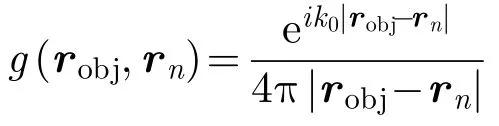
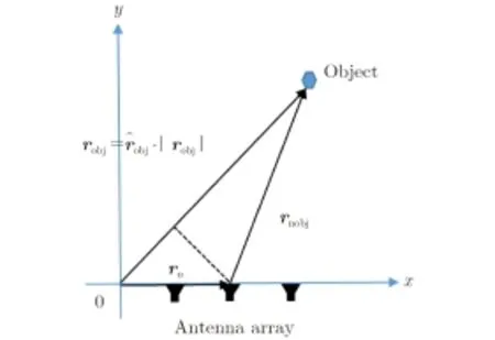
Fig.1 The illustrated map of far-field approximation
For the purpose of short-range imaging,above far-field approximation cannot be satisfied since the distance between probed objects and antennas is usually smaller than 10λ,which brings significant error for locating the objects under investigation.To show this point,a numerical simulation is implemented and its corresponding result achieved by running the strategy of traditional coprime array is shown in Fig.2,where one near-field point target is located at(0,λ).


Fig.2 The result achieved by using the standard coprime array developed in Ref.[1],where the probed object is a point target located at(0,λ)and λ=1 m.The x-axis corresponds to the azimuth angle ranging within(-π,π)rad,while y-axis denotesecho intensity
The rest of this paper is organized as follows.A brief overview of standard co-prime array is made in Subsection 2.1,followed by presenting our methodology of coprime array for the problem of short-range radar detection in Subsection 2.2.Afterwards,the performance of proposed methodology for the TWI application is investigated in Subsection 2.3.Section 3 presents a selected number of numerical simulations to demonstrate the usefulness of proposed methodology.Finally,some conclusions are summarized in Section 4.
2 Problem Statement and Proposed Methodology
This section is devoted to present the operational principal of the(M,N)-coprime array for resolving the problem of short-range radar imaging.To proceed our discussion,the basic concepts of co-prime array is briefly overviewed for following comparison.
2.1Basic properties of P.P.Vaidyanathan and P.Pal's coprime array[1]
Following notations adopted in Ref.[1],the(M,N)-coprime array consists of a coprime pair of ULAs,where one is of M sensors with an interelement spacing of Nλ/2,whereas the other is of N elements with an inter-element spacing of Mλ/2.For the purpose of active coprime sensing,one of two constituting subarrays of(M,N)-coprime array configuration is used for the purpose of transmitting signal,and the other is for receiving signal.The transmitting array with M taps h(n)has a beam pattern(or called antenna pattern):
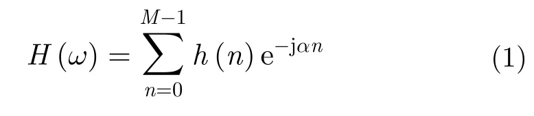
where α=2πdsinθ/λ,and ω=πsinθ.Taking the inter-element spacing denoted by d to be d=Nλ/2,the resulting beam pattern becomes:

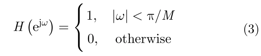
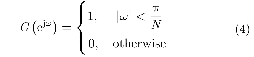
Assuming that H(ω)is ideal low-pass,specifically,

Introducing two sets of array-banks:

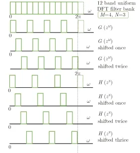
Fig.3 Hk(Z)and Gl(Z)are shifted versions ofandin increment of 2π/MN,respectively.Here,M=4 and N=3 are considered[1]
Note that above conclusion relies on the assumption of ideal low-pass filter,as demonstrated by Eqs.(3)and(4).However,this kind of filter is obviously infeasible in practice.To bypass this issue,a little bit more sensors are utilized[1].To characterized this issue mathematically,a scenario-dependent factor denoted by τ is introduced,in particular,
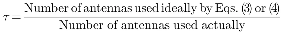
where τ is decided by angle θ of target and antennas,which will be detailed below.
To numerically demonstrate this argument,we conducted a set of simple simulations,where M=9 and N=7 are used.From Fig.4 we can notice that the bandwidth of constructed filter(denoted by red line)is greater than the ideal one,which implies that more sensors,correspondingly,τ=0.64 and 0.5,are required to achieve the desirable resolution.
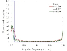
Fig.4 The blue curve stands for the ideal filter when M=9 and N=7.The red curve corresponds to the filter designed with τ=1(M=9 and N=7).In addition,the filters with τ=0.64(M=14 and N=11)and τ=0.5(M=18 and N=14)are denoted by the black and green curve,respectively
2.2Short-range radar imaging using the(M,N)-coprime array
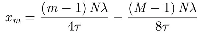
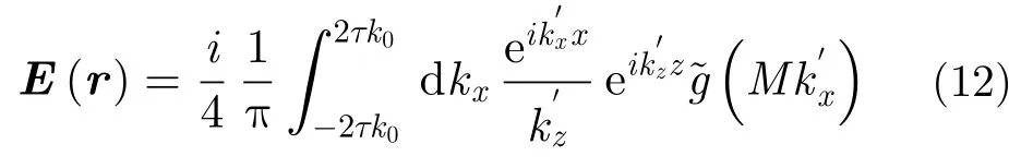
In this subsection,we turn to the discussion of the performance of coprime array for shortrange detection.For the purpose of illustrating operational principle,we restrict the discussion within Two-Dimensional(2D)case where targets are assumed to be infinitely long and invariance along the y-axis.With reference to Fig.5,the coprime array configuration is set as follows:M transmitters and N receivers are uniformly distributed with the intervals of Nλ/4τ and Mλ/4τ,respectively,along the line z=0.The probed ob-ject falls into the investigation domain denoted by Dinv,and f means working frequency.
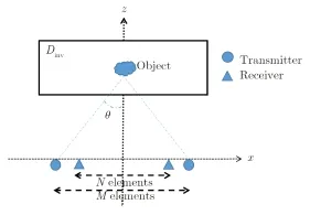
Fig.5 The structure is demonstrated with the background medium being free space.θ is denoted as the angle of targets and antennas
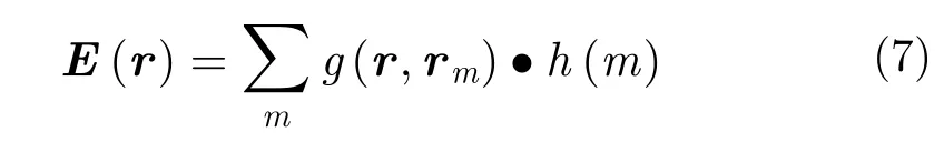
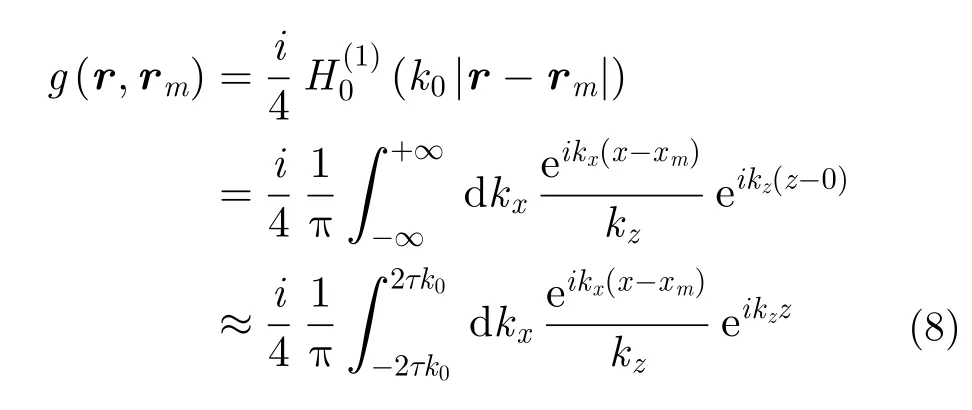
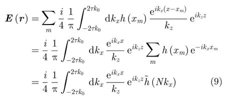
As pointed out previously,the theory of coprime array in literatures relies on the far-field assumption,as implied in Eq.(1).Apparently,such theory should be modified for the shortrange scenario.For this purpose,instead of Eq.(1),the beam pattern arising from an M-elements ULA can be formulated as:

Similarly,the beam pattern of N-element receiving subarray can be formulated as:
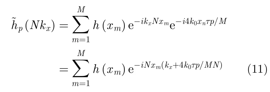
and corresponding receiver N-filter array-banks:


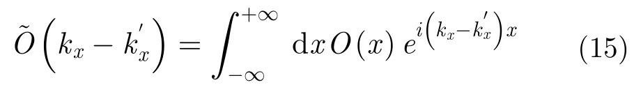
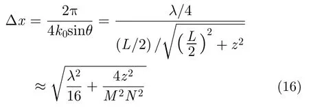
where L denotes the view length on of sensors,and z is the vertical location of targets center.It can be deduced from Eq.(16)that the imaging resolution is proportional to the working wavelength and the distance between probed object and sensors.In addition,the resolution Δx is inverse proportional to the values of M and N,which really makes sense since the more sensors provide more independent measurements.
2.3TWI application of coprime array
This subsection investigates the performance of coprime array for TWI imaging.A simple TWI scenario is illustrated in Fig.6.M transmitters and N receivers are along the line z=znand uniformly distributed with the intervals of Nλ/4τ and Mλ/4τ,respectively.τ can be determined by performing the so-called stationary phase method[8].
Similar to above,the radiation pattern arising from M-elements transmitting array reads:

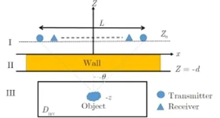
Fig.6 Regions I and III are free space in which the wavenumber is k1and is equal to the free-space wavenumber k0.Region II is the wall whose relative permittivity,and thickness are denoted as εband d,where the wavenumber is k2.The targets are located in the investigated region Dinvbeing parallel to x-axis at vertical range-z.f is the working frequency[8]
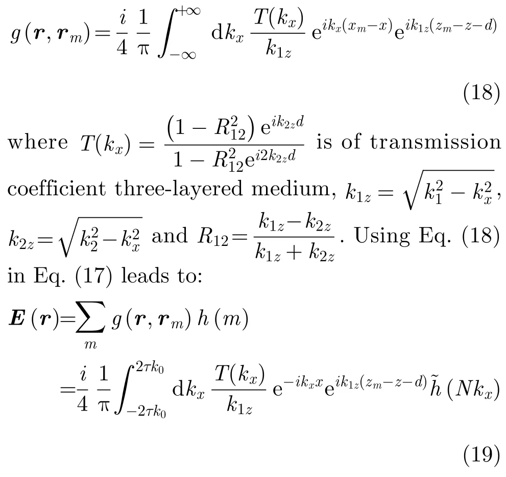
Here,as opposed to Eq.(7),the Green's function takes the one for the three-layered medium sketech in Fig.6,in particular[7],
Similarly,the beam pattern of N-element receiving array is:

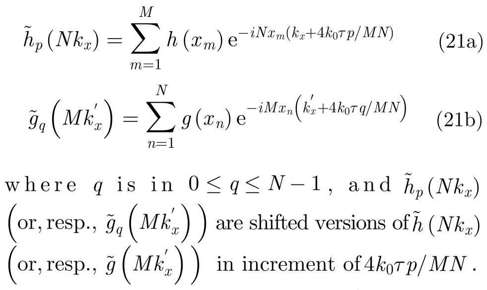
and the transmitting M-filter and receiving N-filter array-bank are respectively introduced as


3 Numerical Results
In order to demonstrate the usefulness of coprime array configuration for short-range radar detection,some numerical simulations achieved by performing the method described in Subsection 2.2 and Subsection 2.3 are provided in this section.
3.1Results for free-space scenario
Firstly,the imaging resolution of coprime array is investigated for different distance denoted by z between sensors and probed object.For this set of simulations,simulation parameters are set as follows:the working frequency is set to be 300 MHz,and the number of transmitter and receiver is M=9 and N=7 respectively.
In comparison to that in Fig.7(a),we can immediately observe that the targets in Fig.7(b)can be identified more easily and clearly.the prediction made in Subsection 2.2 can be justified:the closer the object ranges from sensor,the better the achieveable resolution is while the detected area decreased.
Fig.7 The simulation results when different z between sensors and probed objectis set.Each peak point corresponds to one target.The xaxis denotes the location of object along x-axis(in m)while y-axis for the normalized intensity of targets
Secondly,we would like to investigate the effect of working frequency on imaging resolution,where simulation parameters are the same as those adopted above unless otherwise stated.For these two cases,the system parameters are set as follows:the number of transmitter and receiver are with same as above,but with inter-element space 0.3 m.Additionally,comparing Fig.8(a)with Fig.8(b),we can observe that the higher the operational frequency is,the better the achievable resolution is,and the smaller the detected area is.

3.2Results for TWI scenario
Some simulations have been done in flowing subsection for TWI scenario,which is regarded as an important application for our proposed method.Assuming the working frequency is 2.5 GHz.The number of transmitter and receiver are M=9 and N=7 respectively.The antennas are located at z=0.1 m.The permittivity and thickness of the wall are denoted as εr=9 and d=0.3 m.From simulation results of Fig.10,the conclusion predicted in previous section can be verified.
Fig.8 simulation results when different work frequency f is set
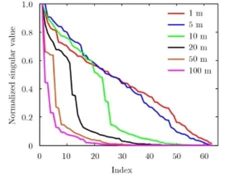
Fig.9 Demonstrates that the normalized SVD of A matrix when objects are set with different ranges z=1 m,5 m,10 m,20 m,50 m ,and 100 m
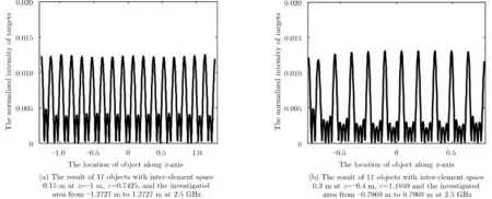
Fig.10 The simulation results when different parameters are set for TWI scenario
4 Conclusion
Appendix:
Firstly,we prove the completeness by showing that there is no holes in the achievable spectrum of object(see Fig.A-1).To that end,we would like to build more general notations involved in Subsection 2.2 as following:
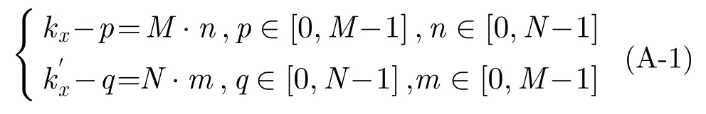
From Eq.(1)one can deduce into

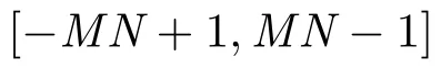

Fig.A-1 When N.m+q=0 and M.n+p=0,can cover [0,MN-1] and [-MN+1,0] shown in Fig.A1(a)and Fig.A1(b)respectively.So the(M,N)-coprime array can obtain all the information of spatial spectrum of objects inIt is demonstrated for M=4 and N=3
References
[1]Vaidyanathan P P and Pal P.Sparse sensing with co-prime samples and arrays[J].IEEE Transactions on Signal Processing,2011,59(2):573-586.
[2]Vaidyanathan P P and Pal P.Theory of sparse coprime sensing in multiple dimensions[J].IEEE Transactions on Signal Processing,2011,59(8):3592-3608.
[3]Qin S,Zhang Y D,and Amin M G.Generalized coprime array configurations for direction-of-arrival estimation[J].IEEE Transactions on Signal Processing,2015,63(6):1377-1390.
[4]Tan Z,Eldar Y C,and Nehorai A.Direction of arrival estimation using co-prime arrays:a super resolution viewpoint[J].IEEE Transactions on Signal Processing,2014,62(21):5565-5576.
[5]Tan Z and Nehorai A.Sparse direction of arrival estimation using co-prime arrays with off-grid targets[J].IEEE Signal Processing Letters,2014,21(1):26-29.
[6]Wang L and Li L.Through-the-wall target localization and tracking using co-prime array[C].The 5th Asia-Pacific Conference on Synthetic Aperture Radar,Singapore,2015.
[7]Chew W C.Waves and Fields in Inhomogeneous Media[M].Wiley-IEEE Press,1995:20-23.
[8]Li L,Zhang W,and Li F.A novel autofocusing approach for real-time through-wall imaging under unknown wall characteristics[J].IEEE Transactions on Geoscience and Remote Sensing,2010,48(1):423-431.

Wang Longgang was born in 1988.He received his B.Eng degree in communication engineering from the Tianjin University.He is currently working toward the Ph.D.degree in Peking University.His research interest is highresolution microwave imaging methods.
E-mail:longgang.wang@pku.edu.cn

Li Lianlin was born in 1980.He received his Ph.D.degree from the Institute of Electronics,Chinese Academy of Sciences in 2006.He is currently a hundred talented program professor with Peking University.His research interests are super-resolution imaging,microwave imaging,sparse signal processing,and ultrawideband radar systems.
10.12000/JR16022
基于互质阵列雷达技术的近距离目标探测方法
王龙刚李廉林
(北京大学信息科学技术学院北京100871)
一组(M,N)互质阵列由两组结构化排列的子阵列构成:一组包括M个天线单元,另一组包括N个天线单元。互质阵列稀疏天线仅需要M+N-1个收发天线单元就可实现对O(MN)个远距离目标的识别。在相同分辨条件下,互质阵列雷达技术可利用更少的收发单元来识别更多的雷达目标。因此互质阵列雷达技术能够极大地降低传统雷达收发系统的复杂度。但是,现有文献中所讨论的互质阵列雷达技术均基于远场近似假设,当探测近距离目标时,会由于目标邻近天线单元而产生严重的探测误差。为了解决上述问题,该文将标准的互质阵列雷达技术的适用范围扩展到用于解决近距离目标探测。该文论证了(M,N)互质阵列雷达技术能够以4τk0/MN空域分辨率恢复[-2τk0,2τk0]空域范围内的目标信息,其中k0表示自由空间波数,τ是场景因子。由此可见(M,N)互质阵列能够以λ/4τ的方位向分辨率获得O(MN)个近距离目标方位向位置信息。该文进一步论证了互质阵列雷达技术在穿墙成像中的适用性。最后,该文提供了一组数值仿真实验结果,验证了互质阵列雷达技术对于近距离目标探测的有效性。
互质阵列;雷达探测;穿墙成像;近距离
TN957.51
A
2095-283X(2016)03-0244-10
Manuscript received Janurary 27,2016; Revised May 17,2016.Published online June 15,2016.Foundation Item:The National Natural Science Foundation of China(61471006).
*Communication author:Li Lianlin.
E-mail:lianlin.li@pku.edu.cn.