New method for oblique impact dynamics research of a flexible beam with large overall motion considering impact friction force
2016-09-23YuanLiZhangHong
W.Yuan·L.Li·D.G.Zhang·J.Z.Hong
RESEARCH PAPER
New method for oblique impact dynamics research of a flexible beam with large overall motion considering impact friction force
W.Yuan1·L.Li1·D.G.Zhang1·J.Z.Hong2
©The Chinese Society of Theoretical and Applied Mechanics;Institute of Mechanics,Chinese Academy of Sciences and Springer-Verlag Berlin Heidelberg 2016
Aflexiblebeamwithlargeoverallrotatingmotion impacting with a rigid slope is studied in this paper.The tangential friction force caused by the oblique impact is analyzed.The tangential motion of the system is divided into a stick state and a slip state.The contact constraint model and Coulomb friction model are used respectively to deal with the two states.Based on this hybrid modeling method,dynamic equations of the system,which include all states(before,during,and after the collision)are obtained.Simulation results of a concrete example are compared with the results obtained from two other models:a nontangential friction model and a modified Coulomb model.Differences in the results from the three models are discussed.The tangential friction force cannot be ignored when an oblique impact occurs.In addition,the results obtained from the model proposed in this paper are more consistent with real movement.
Flexible beam·Oblique impact·Stiction·Slip
1 Introduction
In many fields like aviation,aerospace,vehicle engineering,and robotics,contact-impact problems,such as the deployment of a solar panel or the docking of spacecraft,are very common.The collision between objects can lead to a speed jump,the mutation of energy,and the generation of huge impact forces;thus,this has become a focus of research on multibody systems,which has emerged as a particularly important issue in recent years.At present many researchers still focus on normal impact forces because the friction between objects can be ignored during normal impact.But normalimpactisanidealstatus.Moreoften,inpracticalengineering what happens is an oblique impact,which is much more complex.Thus,the effects of tangential friction force on a system undergoing an oblique impact should not be ignored.
Nowadays more and more experts and scholars are paying attention to the oblique impact dynamics of multibody systems and have made much progress in dynamic modeling,numerical methods,and collision experiments.Deck et al.[1,2]studied collisions caused by joint clearance.They used a Coulomb friction model to calculate the friction force during a collision.But this approach ignored the stick state of collisions because the friction force was a function of the sliding velocity[3].It was obviously inconsistent with real movement,so the numerical calculation results of this theory were not very accurate.Nordmark et al.[4],Stronge[5],and Yao et al.[6]used composite coefficients to obtain different patterns of behavior during collisions.They investigated whether and when an initial slip was brought to rest and whether the slip resumed or stiction occurred following stoppage of the initial slip.Djerassi[7-9]thought that the duration of contact-impact was nearly zero in terms of the assumptionoftherigidbodyimpact.Inhisstudies,Newton’s[10],Poisson’s[11],and Stronge’s hypotheses[12]were utilized to define the coefficient of restitution.Lankarani[13]andLankarani andPereira[14]usedNewton’s andPoisson’s hypotheses and an extension of Routh’s graphical method to obtain a general formulation that showed the mode of theimpact(sliding,sticking,andreversesliding).Theyclassified impacts into seven situations during periods of compression orrestitution.WangandMason[15]usedNewton’sandPoisson’s hypotheses to deal with planar collisions.Djerassi[16]pointed out some shortcomings of those classical hypotheses proposed by Newton,Poisson,and Stronge,which were widelyused.Zhaoetal.[17,18]tookanormalimpulseasthe independent differential variable in terms of Lagrange equations.He used Poisson’s coefficient of restitution to obtain the duration of the integral of those differential equations. A searching algorithm presented by Bhatt and Koechling[19,20]was developed to determine the resumed direction of tangential movements.A phenomenon widely known as the Painlevé paradox[21-23],which may exist in multibody systems with oblique impact,is also examined.When the Painlevé paradox occurs as a result of some initial conditions and inertia properties,there will be multiple solutions ornosolutionsofthedynamicequations.HanandHong[24]proposedamultivariablemethodforamultibodysystemwith impact.Qietal.[25]usedamethodtoobtainforcesandpositions when kinematic constraints of prismatic joints remain. Peng et al.[26]proposed the dynamic modeling to deal with a rigid multibody system with fixed bilateral constraints and multi-friction.Han et al.[27,28]studied theoretically and experimentally the dynamics of an oblique-impact vibrating system.Jin et al.[29]developed a piecewise method to describe the sliding motion during an oblique impact.
A new method considering the tangential friction force during oblique impact is proposed in this paper.In Sect.2,a physicalmodelofasystemthatcontainsaflexiblebeamwith large overall rotating motion impacting with a rigid slope is described.The method of assumed modes is used to discretizedeformationsofthebeam.InSect.3,therigid-flexible coupling dynamics equations of a collision-free system are derived.Based on the contact constraint method,the normal impact force of a frictionless system is analyzed in Sect.4. In Sect.5,the contact constraint model and Coulomb friction model are used to deal respectively with the stick state and slip state during oblique impact.In Sect.6,the judgment law of contact-impact is given.The dynamic equations of the system,which include all states(before,during,and after collision)are obtained.In Sect.7,simulation results of the hybrid model are compared with those obtained from two other models:the nontangential friction model and the modified Coulomb model.Final conclusions summarizing the obtained results are given in Sect.8.
2 Physical model of system
Aflexiblebeaminthegravityfieldwithlargeoverallrotating motionisshowninFig.1.Apoint P onthebeamimpactswith a point P′on the rigid slope.The parameters of the flexiblebeam are as follows:length L,cross-sectional area A,mass density ρ,Young’s modulus E,and moment of inertia Iz. An inertial coordinate system Oxy with unit vectors i and j is established at the rotating joint O.A floating coordinate system OXY with unit vectors i′and j′is established at the flexible beam whose x-axis coincides with the neutral axis of the undeformed beam.A coordinate system with origin O1on the rigid slope is denoted by O1X1Y1.The Cartesian coordinatesofapoint O1are(X01,Y01)inthe OXY system,and the angle of the slope is α.
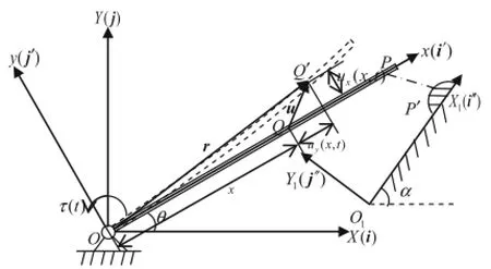
Fig.1 Schematic of collision system
The flexible beam is assumed to be an Euler-Bernoulli beamwhosedeformationisquitesmall.Toimprovetheoperation efficiency,the longitudinal deformation of the beam is neglected.Thetransversebendingdeformationandthelongitudinal shortening of the beam(which is called the coupling deformation[30-32])caused by the transverse deformation are considered here.In the floating coordinate system,a point Q(x,0)on the beam before deformation will move to Q′(x′,y′)after deformation,and its displacement vector in the floating coordinate system is

where ux(x,t)is the axial deformation displacement of the point Q,and uy(x,t)is its transverse deformation displacement.
The method of assumed modes is used to discretize the axial and transverse deformation displacements of the beam

where

3 Rigid-flexible coupling dynamic equations of collision-free systems
In the inertial coordinate system,the position vector of the point Q(x,0)on the beam after deformation is

whereW isthedirectioncosinematrixfromtheinertialcoordinate system tothe floating coordinate system,and ρ0is the position of Q in the floating coordinate system before deformation.
The kinetic energy of the system is given by

The potential energy of the system is given by

in which R= ■L0ρAh(x)dx,VEand VGare the elastic potential energy and the gravitational potential energy of the beam,respectively,g is the vector array of the gravitational acceleration in the inertial coordinate system,and h is the position vector array of point Q in the floating coordinate system after deformation.
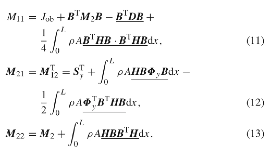
Let q=[θ,B1,B2,...,BN]Tbe the generalized coordinates.According to the Lagrange equations of the second kind,the rigid-flexible coupling dynamic equations of the system can be obtained as follows

where

where
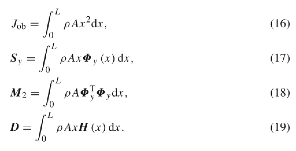
Because the coupling deformation in the process of modeling was considered,the preceding equations have additional coupling terms,which are underlined.
4 Impact dynamic equations of frictionless system
4.1 Establishment of rigid-flexible coupling dynamic equations
The impact point P on the beam collides with the rigid slope O1X1Y1at some time.The first step is to obtain the normal impact force by using the contact constraint method in the normal direction of the slope.Add the normal contact constraint equations to the collision-free dynamic equations to establish the dynamic equations of the frictionless system.The impact point P on the beam and the contact point P′on the slope have the same displacement,so the contact constraintconditionisthatthedisplacementYFoftheimpact point P inthenormaldirectionoftherigidslopestaysatzero in the slope coordinate system during a collision.Hence,the constraintequationsofthedisplacement,velocity,andacceleration can be written as follows
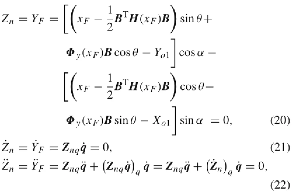
where
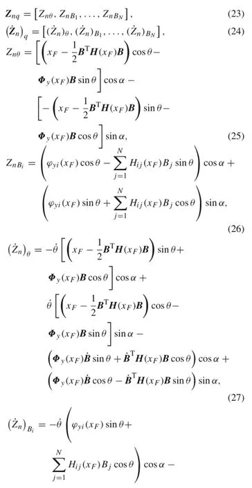
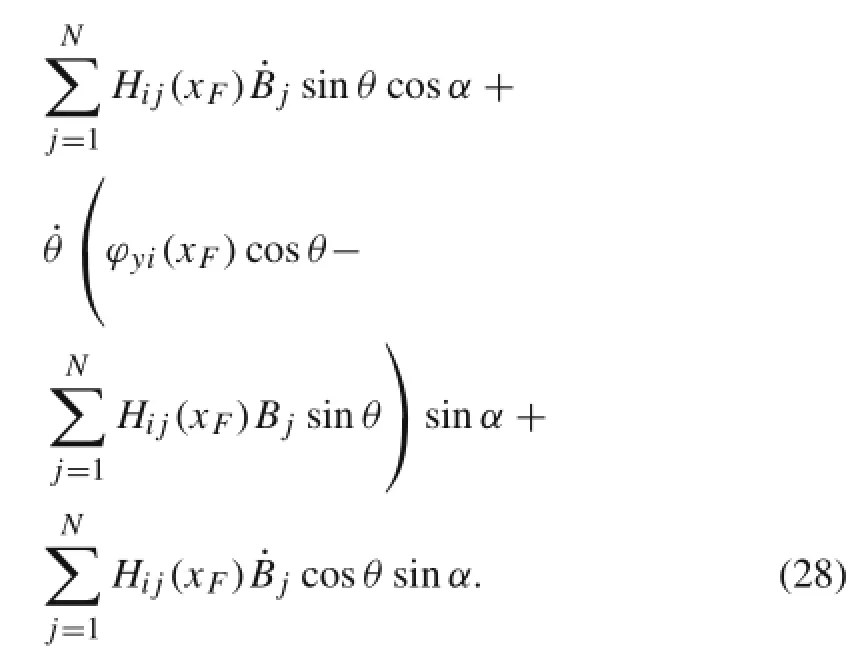
AccordingtoEq.(22),thenormalcontactconstraintequation is written as follows
CombiningEq.(10)withEq.(29)yieldstheimpactdynamic equations of the frictionless system where only the normal impact force is considered
where q is the generalized coordinate vector,M and QIare the generalized mass matrix and the generalized force vector of the collision-free system,respectively,Znq∈R1×nis the Jacobian matrix,and λnis the Lagrange multiplier,which is the normal impact force.
To satisfy the compatibility condition,Baumgarte’s stabilization method[33]is introduced here.The constraint equation(22)of the acceleration are transformed as follows

Accordingly,theimpactdynamicequationsofthefrictionless system are transformed into

Based on Eq.(23),the Lagrange multiplier is written as

Substituting λninto Eq.(32),we can obtain closed ordinary differential equations.Then¨q of this moment can be calculated.q and˙q of the next moment can be obtained by solving the ordinary differential equationin which QIIis the new generalized force array considering the normal impact force.

4.2 Determining initial collision conditions
Theimpulse-momentummethodcanbeappliedatthebeginning of a collision to bring about the transition of the initial conditions from the collision-free stage to the collision stage and avoid uncoordinated movements caused by adding contact constraints directly.The impulse-momentum method is adopted to obtain the initial conditions of the collision.The coefficient of restitution e is set to zero.The velocity of impact point P on the beam,which isinthe normal direction oftheslope,suddenlybecomeszero.Duringthecollision,the displacement,velocity,and acceleration of impact point P in the slope coordinate system Y1direction are always zero. The position of impact point P is defined as(xF,0)in the floatingcoordinatesystembeforedeformation.Theimpulsemomentumimpactdynamicequationofthesystemaregiven by[34]

where vn0is the velocity projection of impact point P along the normal direction of the slope before the collision,Dn∈Rn×1isann-dimensionalarray,and I isthecollisionimpulse:

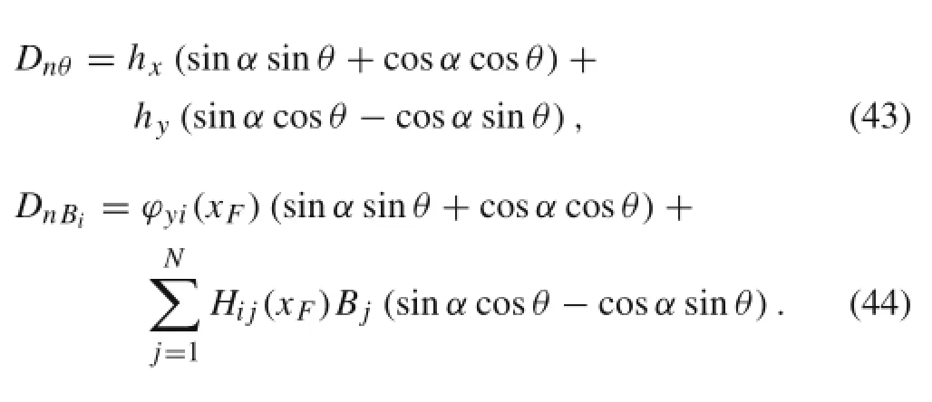
M,Dn,andvn0arecalculatedbeforethecollision.According to Eq.(36),the collision impulse and the increments of the generalized velocities are obtained as follows

Finally,the generalized velocity of the system after collision can be written as

5 Oblique impact dynamic equations of system with friction
Thetangentialmotionofimpactpoint P ontheflexiblebeam can be classified as slip state and stick state,and these two statesmayinterchangeundercertainconditions.Becausethe tangential impact forces of the two states are not the same,their corresponding impact dynamic equations need to be established.The integrated model that can deal with these two states is called the hybrid model.
5.1 Stick state
When a system is in the stick state,impact point P on the beam and contact point P′on the slope have the same displacement in the tangential direction of the slope during a collision,which means that the contact constraint method can still be adopted.Hence,the constraint equations of the tangential displacement,velocity,and acceleration can be written as follows

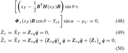
where
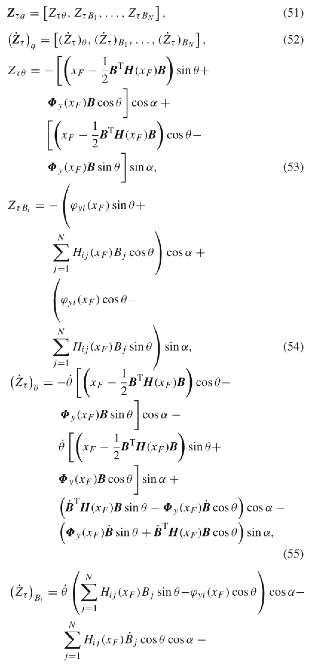

AccordingtoEq.(50),thetangentialcontactconstraintequation is obtained as follows

Combining Eq.(32)of the frictionless system with the tangential contact constraint equation(56),the impact dynamic equations under the stick state can be written as

in which Zτq∈R1×nis the Jacobian matrix,and λτis the Lagrange multiplier that is the tangential friction force.
Equation(58)can be simplified to

BasedonBaumgarte’sstabilizationmethod,Eq.(50)istransformed into

Accordingly,theimpactdynamicequationsofthesystemare transformed into

Based on Eq.(61),the Lagrange multiplier is obtained by

Substituting the Lagrange multiplier λτinto Eq.(61),we can calculate¨q at this moment and then obtain q and˙q of the next moment by solving the ordinary differential equations. The oblique impact dynamic equations of the stick state are written as follows

5.2 Slip state
When the system is in the slip state,based on Coulomb’s law of friction,the friction force can be expressed as

where μkis the sliding friction coefficient,λnis the normal impact force,and vτis the tangential velocity during the sliding

In every very short time step,the tangential friction varies continuously.Thus,the concept of oblique impact force potentialenergyisintroducedhere.Thefrictionforceistaken as a potential force whose corresponding generalized impact forces need to be calculated.
The oblique impact force potential energy is written as

The corresponding generalized impact forces are given as follows
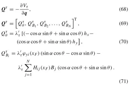
Hence,theobliqueimpactdynamicequationsoftheslipstate can be expressed as

5.3 Determination of type of oblique impact
Assuming that the impact point is in the stick state,the normal impact force λnand the tangential friction force λτcan be calculated using the contact constraint model.μsis the maximum static friction coefficient.If|λτ|≤|μsλn|,then theassumptionisvalidandλτisthetangentialfrictionforce; if|λτ|>|μsλn|,then the status of motion is slip state and the tangential friction force becomes
6 Judgment law of contact-impact
Todeterminewhetherornotacollisionoccurs,thefollowing equation is used:

where Znis the distance of two contact bodies along the normaldirectionoftheslopeintheslopecoordinatesystem.The position of impact point P in the inertial coordinate system is(XF,YF);ρyand ρy′are the coordinate components of P on the flexible beam and P′on the slope along the O1Y1direction in the O1X1Y1system,respectively.
Before collision,the dynamic equation of the system is Eq.(10).If Zn<0 and˙Zn<0,then the flexible beam and therigidslopebegintocomeintocontact.Atthismomentthe impulse-momentum method is adopted to determine the initial conditions of the collision due to the contact constraints added to the system,and then the calculation of the collision stage begins.Which impact state(stick or slip)it is in at each successive time step is analyzed.If the system is in the stick state,the impact dynamic equation is Eq.(64);if the system is in the slip state,the impact dynamic equation transforms into Eq.(72).During the collision,we wish to determine whether the directions of the normal contact constraint counterforces of two adjacent moments are the same. Ifthedirectionsarethesame,thesystemisstillintheprocess of collision.Otherwise,the opposite directions indicate the collision is over,and the dynamic equations of the system transform into Eq.(10).
7 Simulation results
TheparametersoftheflexiblebeaminFig.1aregivenasfollows:L=1.0 m,A=3.14×10⁻⁴m2,ρ=2766.7kg/m3,E=68.952GPa,I=7.85×10-9m4.The flexible beam falls freely in the gravity field.The initial angular velocity of the beam is zero.The coordinate of the origin of the slope coordinatesystemis(0.3 m,0)intheinertialcoordinatesystem.The angle of the slope α is π/10,and the initial angle of the flexible beam θ is π/4.Both the kinetic and maximum static frictional coefficients are 0.3.The parameters of Baumgarte’s stabilization method χ and β are set to 10 and1000,respectively.Thetotalsimulationtimeis1.0s.The time steps of the collision-free stage and the collision stage are 1.0×10⁻⁴and 1.0×10⁻⁶s,respectively.The nontangential friction model and the modified Coulomb model[35]arealsousedtocomparewiththesimulationresultsofthehybrid model proposed in this article.

Fig.2 Tangential friction force of impact point
Figure 2 shows the real-time variations of the tangential friction force.It can be seen that the first macro collision occurs at t≈0.325s.The curves of the hybrid model and the modified Coulomb model generally coincide with each other during the first collision stage,but some slight differences still exist between them.The differences in the results during subsequent collisions become to increase gradually. This is because the friction of the modified Coulomb model,which cannot reflect the static stage of the friction,is a function of the relative velocity of the impact points.Obviously,the modified Coulomb model fails to deal with the system containing stick-slip motions.Hence,it is quite normal that therearesomedifferences between theresultsobtained from these two models.The stick motion and the slip motion can interchange under certain conditions when the hybrid model is used,and this motion switch is more consistent with real movement.
Figure 3 shows the real-time variations of the normal impact force.It can be seen from the figure that the normal impactforcescalculatedbythethreemodelsvarywidelyover time,andtheircurvesagreefairlywellwitheachotherduring the first macro collision stage.Affected by the differences in the oblique friction owing to the first macro collision,the curves become separated during subsequent collisions.The differences between the impact time and the normal impact force remain slight but will become increasingly obvious as the collision times increase.
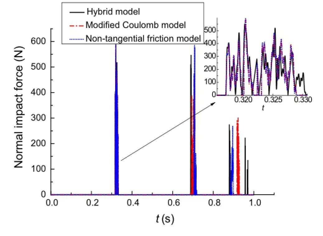
Fig.3 Normal impact force of impact point
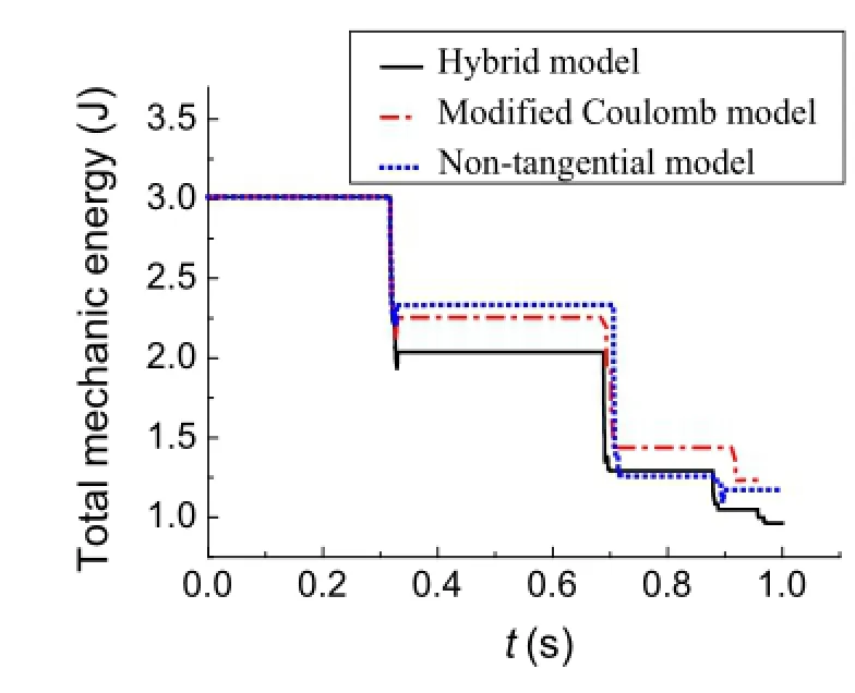
Fig.4 Total mechanical energy
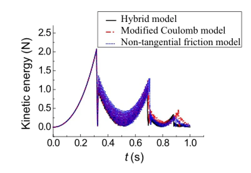
Fig.5 Kinetic energy
The variations of the total mechanical energy,kinetic energy,gravitational potential energy,and elastic potential energyofthesystemwithrespecttotime,calculatedusingthe three models,are shown in Figs.4,5,6,and 7,respectively. As shown in Fig.4,during the initial collision-free stage,the totalmechanicalenergyremainsconstantsinceonlytheconservative forces do the work.After the first macro collision, the total mechanical energy decays quickly.This illustrates that the collision can cause considerable loss of energy.The energy loss of the system calculated using the hybrid model is the largest while the energy loss of the system calculated using the nontangential friction model is the smallest,which proves that tangential friction can cause some energy loss to the system,so its influence cannot be ignored.As shown in Figs.?5,?6,and?7,during the initial collision-free stage,thekineticenergyandthegravitationalpotentialenergyconvert mutually and the value of the elastic potential energy isvery small.After collision,all results from the three models change suddenly.The elastic potential energy is no longer zero since the collision causes the deformation of the flexible beam(Figs.8 and 9).After the first macro collision,the kinetic energy,the gravitational potential energy,and the elasticpotentialenergycalculatedusingthehybridmodelare all smaller than those calculated using the other two models,which is consistent with its largest mechanical energy loss observed in Fig.4.
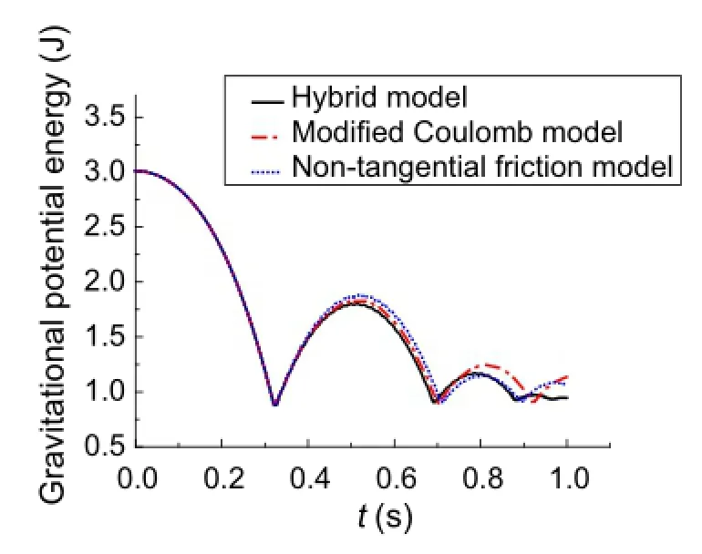
Fig.6 Gravitational potential energy
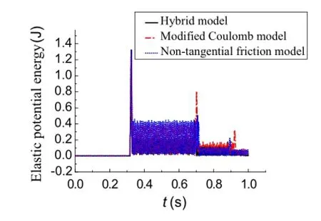
Fig.7 Elastic potential energy

Fig.8 Rotation angle of joint O

Fig.9 Rotation angular velocity
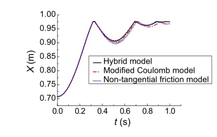
Fig.10 X axial displacement of impact point
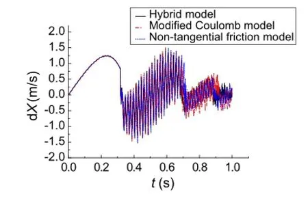
Fig.11 X axial velocity of impact point
Figures 10 and 11 show respectively the displacements and velocities of the impact point along the OX direction. Figures 12 and 13 show respectively the displacements and velocities of the impact point along the OY direction.It can beseenthatthecurvesobtainedusingthethreemodelsareall thesamebeforecollision.Aftertheflexiblebeamimpactsthe rigidslope,thecurvesnolongercoincidewellwitheachother owing to the influence of the tangential friction.Although therearesomeslightdifferencesbetweentheresultsobtained fromthesethreemodels,thevaryingtendenciesofthecurves are generally similar.
Figure 14 shows the displacement of the impact point along the O1X1direction.Figures 15 and 16 are partial enlargedviewsofFig.14duringthefirstmacrocollisionand the second macro collision,respectively.It can be seen from Fig.14 that the tangential displacement of the impact point that first increases to the maximum and then decreases obviously changes during the initial collision-free stage.After the system undergoes collision,the change in the displacement becomes smaller with the increase in collision times. In addition,only slip occurs during the first macro collison while stick and slip both occur during subsequent collisions.Figure 15 shows how the impact point keeps sliding along the tangential direction of the slope during the first macro collison andthe directionof slipchanges at t≈0.325 s.Figure 16 shows how the impact point remains in the slip state during the initial stage of the second macro collision.Then it changes to the stick state at t≈0.699 s and remains viscous until the collision ends.
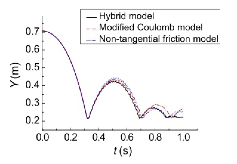
Fig.12 Y-axial displacement of impact point

Fig.13 Y-axial velocity of impact point
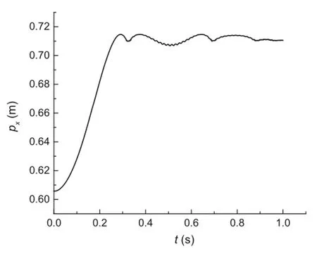
Fig.14 Displacement of impact point along O1X1axial
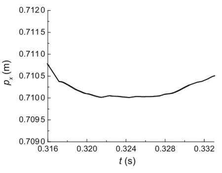
Fig.15 Displacement along O1X1axial during first collision
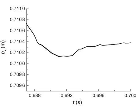
Fig.16 Displacement along O1X1axial during second collision
8 Conclusions
This article examines a flexible beam with a large overall rotating motion impacting with a rigid slope.A new hybrid method is proposed based on the contact constraint method. The contact constraint model and Coulomb friction model are used to deal with the stick state and the slip state,respectively.Forcomparison,twoothermodels-thenontangential friction model and the modified Coulomb model-are also used.The simulation results show that the varying tendencies of the three models’curves are generally similar,which confirms the accuracy and rationality of the present model. The tangential friction force can cause a loss of energy in the system,resulting in changes in dynamic responses,so this force cannot be ignored when the system is undergoing an oblique impact.It is easy to see the hybrid model is more consistent with the real movement.In addition,a rigid slope whose position can be in any direction has a wider range of application.Thus,further study of multibody systems with oblique impacts is warranted.
Acknowledgments The project was supported by the National Natural Science Foundation of China(Grants 11272155,11132007,and 11502113),the 333 Project of Jiangsu Province in China(Grant BRA2011172),and the Fundamental Research Funds for Central Universities(Grant 30920130112009).
References
1.Deck,J.F.,Dubowsky,S.:On the limitations of predictions of the dynamic response of machines with clearance connections.J. Mech.Design 116,833-841(1994)
2.Zhuang,F.F.,Wang,Q.:Modeling and analysis of rigid multibody systems with driving constraints and frictional translation joints. Acta Mech.Sin.30,437-446(2014)
3.Song,P.,Krauss,P.,Kumar,V.,et al.:Analysis of rigid-body dynamicmodelsforsimulationofsystemswithfrictionalcontracts. J.Appl.Mech.68,28-118(2001)
4.Nordmark,A.,Dankowicz,H.,Champneys,A.:Discontinuityinduced bifurcations in systems with impact and friction:discontinuities in the impact law.Int.J.Nonlinear Mech.44,1011-1023(2009)
5.Stronge,W.J.:Smooth dynamics of oblique impact with friction. Int.J.Impact Eng.51,36-49(2013)
6.Yao,W.,Chen,B.,Liu,C.:Energetic coefficient of restitution for planar impact in multi-rigid-body systems with friction.Int. J.Impact Eng.31,65-255(2004)
7.Djerassi,S.:Collision with friction;part a:Newton’s hypothesis. Multibody Syst.Dyn.21,37-54(2009)
8.Djerassi,S.:Collisionwithfriction;partB:Poisson’sandStornge’s hypothesis.Multibody Syst.Dyn.21,55-70(2009)
9.Djerassi,S.:Three-dimensional,one-point collision with friction. Multibody Syst.Dyn.27,173-195(2012)
10.Kane,T.R.:A dynamic puzzle.Stanford Mech.Alumni Club Newsl.6(1984)
11.Routh,E.J.:Dynamics of a System of Rigid Bodies,Elementary Part,7th edn.Dover,New York(1905)
12.Stronge,W.J.:Frictionincollision:resolutionofaparadox.J.Appl. Phys.69,610-612(1991)
13.Lankarani,H.M.:A Poisson-based formulation for frictional impact analysis of multibody mechanical systems with open or closed kinematical chains.J.Mech.Design 122,489-497(2000)
14.Lankarani,H.M.,Pereira,M.F.O.S.:Treatmentofimpactwithfrictioninplanarmultibodymechanicalsystems.MultibodySyst.Dyn. 6,203-227(2001)
15.Wang,Y.,Mason,M.T.:Two-dimensionalrigidbodycollisionwith friction.J.Appl.Mech.59,635-642(1992)
16.Djerassi,S.:Stronge’s hypothesis-based solution to the planar collision-with-frictionproblem.MultibodySyst.Dyn.24,493-515(2010)
17.Zhao,Z.,Liu,C.,Chen,B.:The numerical method for threedimensional impact with friction of multi-rigid-body system.Sci. China Ser.G-Phys.Mech.Astron.49,102-118(2006)
18.Zhao,Z.,Liu,C.:The analysis and simulation for threedimensional impact with friction.Multibody Syst.Dyn.18,511-530(2007)
19.Bhatt,V.,Koechling,J.:Partitioningtheparameterspaceaccording to different behaviors during three-dimensional impacts.J.Appl. Mech.62,740-746(1995)
20.Bhatt,V.:Three-dimensional frictional rigid-body impact.J.Appl. Mech.62,893-898(1995)
21.Painlevé,P.:Sur les lois du frottement de glissement.Comptes Rendu des Séances de l’Academie des Sci.121,112-115(1895)
22.Shen,Y.,Stronge,W.J.:Painlevé paradox during oblique impact with friction.Eur.J.Mech.A-Solid 30,457-467(2011)
23.Leine,R.I.,Brogliato,B.,Nijmeijer,H.:PeriodicmotionandbifurcationsinducedbythePainlevéparadox.Eur.J.Mech.A-Solid 21,869-896(2002)
24.Han,S.L.,Hong,J.Z.:Multi-variable method for flexible multibodysystemswithcontact/impact.Chin.J.Theor.Appl.Mech.43,886-893(2011)(in Chinese)
25.Qi,Z.H.,Luo,X.M.,Huang,Z.H.:Frictional contact analysis of spatialprismaticjointsinmultibodysystems.Chin.J.Theor.Appl. Mech.43,571-578(2011)(in Chinese)
26.Peng,H.L.,Wang,S.M.,Wang,Q.,et al.:Modeling and simulation of multi-body systems with multi-friction and fixed bilateral constraint.Chin.J.Theor.Appl.Mech.41,105-112(2009)(in Chinese)
27.Han,W.,Jin,D.P.,Hu,H.Y.:Dynamicsofanoblique-impactvibrating system of two degrees of freedom.J.Sound Vib.275,795-822(2004)
28.Han,W.,Hu,H.Y.,Jin,D.P.:Experimental study on dynamics of an oblique-impact vibrating system of two degrees of freedom. Nonlinear Dyn.50,551-573(2007)
29.Jin,D.P.,Hu,H.Y.,Bishop,S.R.:Piecewise analysis of oblique vibro-impacting systems.Acta Mech.Sin.19,579-584(2003)
30.Duan,Y.C.,Zhang,D.G.:Rigid-flexible coupling dynamics of a flexible robot with impact.Adv.Mater.Res.199-200,245-250(2011)
31.Duan,Y.C.,Zhang,D.G.,Hong,J.Z.:Globalimpactdynamicmodeling and verification of a flexible beam with large overall motion. Adv.Mech.Eng.9,825-836(2013)
32.Duan,Y.C.,Zhang,D.G.,Hong,J.Z.:Partition method for impact dynamics of flexible multibody systems based on contact constraint.Appl.Math.Mech.34,1393-1404(2013)
33.Baumgarte,J.:Stabilization of constraints and integrals of motion in dynamical systems.Comput.Method Appl.Mech.Eng.1,1-16(1972)
34.Huag,E.J.,Wu,S.C.,Yang,S.M.:Dynamicsofmechanicalsystems with Coulomb friction,stiction,impact and constraint additiondeletion theory.Mech.Mach.Theory 21,401-406(1986)
35.Flores,P.,Ambrósio,J.,PimentaClaro,J.C.,etal.:Kinematicsand Dynamics of Multibody Systems with Imperfect Joints:Models and Case Studies.Lecture Notes in Applied and Computational Mechanics.Springer Verlag,Berlin
23 December 2015/Revised:2 March 2016/Accepted:20 April 2016/Published online:25 June 2016
✉ D.G.Zhang zhangdg419@mail.njust.edu.cn
1School of Science,Nanjing University of Science and Technology,Nanjing 210094,China
2Department of Engineering Mechanics,Shanghai Jiao Tong University,Shanghai 200030,China
杂志排行
Acta Mechanica Sinica的其它文章
- Delayed detached eddy simulations of fighter aircraft at high angle of attack
- Plate/shell topological optimization subjected to linear buckling constraints by adopting composite exponential filtering function
- Numerical simulations of the process of multiple shock-flame interactions
- Analytical and finite-element study of optimal strain distribution in various beam shapes for energy harvesting applications
- The comparative analysis of rocks’resistance to forward-slanting disc cutters and traditionally installed disc cutters
- Modal parameter identification of flexible spacecraft using the covariance-driven stochastic subspace identification(SSI-COV)method
