Forces and Stresses During Friction Stir Joining of 2024Aluminum Alloy
2016-09-14DengYongfangZuoDunwenSongBo
Deng Yongfang,Zuo Dunwen,Song Bo
1.College of Mechanical &Electrical Engineering,Nanjing University of Aeronautics and Astronautics,Nanjing 210016,P.R.China;2.Institute of Engineering and Research,Jiangxi University of Science and Technology,Ganzhou 341000,P.R.China(Received 9May 2014;revised 21July 2014;accepted 23July 2014)
Forces and Stresses During Friction Stir Joining of 2024Aluminum Alloy
Deng Yongfang1,2,Zuo Dunwen1*,Song Bo1
1.College of Mechanical &Electrical Engineering,Nanjing University of Aeronautics and Astronautics,Nanjing 210016,P.R.China;
2.Institute of Engineering and Research,Jiangxi University of Science and Technology,
Ganzhou 341000,P.R.China
(Received 9May 2014;revised 21July 2014;accepted 23July 2014)
An attempt is made to measure three direction forces using octagonal ring dynamometer in the 2024aluminum alloy friction stir joining(FSJ)process.A test is made to measure the specific area stress and stress distributions in the specific area of the workpiece are obtained.The workpiece stresses in the FSJ process are analyzed by numerical simulation method.It is found that,in the downward stage of the process,feed force and lateral force in the tool are small,almost zero,and the maximum axial force can reach 12.5kN.In the stable joining stage,the forces acting on the tool become stabilized.Compared with the low speed,high feed speed results in small feed force and small lateral force,but large feed force in the stable joining stage.The stresses in three directions of feed direction,direction that perpendicular to butt face and direction perpendicular to the surface are obtained.The simulation stress value of measure point is obtained.Test and numerical simulation can authenticate each other.Both experimental stress values and numerical simulation stress values are credible.
friction stir joining(FSJ);force;stress;2024aluminum alloy
0 Introduction
Friction stir joining(FSJ,also called friction stir welding(FSW))is a solid state joining process invented by the welding institute(TWI,UK)in 1991[1].Its essence is that frictional heat,which generated by friction between high-speed rotary tool and plates,promotes material softening,mixture and finally to achieve a solid joining[2].FSJ is a complex process with temperature field,stress and strain field,metal flow and other factors mutual coupling and interaction.It is also accompanied by the grain structure transformation in the FSJ process[3-5].While the material type,plate thickness,process parameters,tool geometry and other conditions are different,the forces acting on the tool will be different in the process.Temperature field,stress and strain field,metal flow,grain and microstructure of ma-terials are also different.Measurement of tool force and analysis of stress and strain field of plate in the process have become an important research direction.Measurement of tool force and analysis of stress and strain field of plate in the process have a deep meaning in research of joint forming mechanism,analysis of grain,microstructure and properties of joint,optimization of process parameters and the improvement and development of the device.
Sorensen and Stahl[6]studied feed load in the FSJ process and found that the size of feed load changed with the varying of needle size and radius of the tool.Kumar and Elangovan et al.[7-8]investigated the relationship between axial force,joint organizations,and mechanical properties.Crawford and Cook et al.[9]studied feed load in the FSJ process,and believed there was a certain re-lationship between the feed load and the rotational speed of the tool.Wang,Zhang et al.[10]studied the varying of feed load in the FSJ process and believed that,joining the same material,feed load increased as the joining speed,amount of indentation and the thickness of the material increased;And when joining the different materials,feed load of joining the high hardness material was greater than that of the low hardness material. Wang et al.[11]calculated the force between the workpiece and the tool by measuring the output power of the motor,which driven the horizontal table movement and installed on the FSJ machine. Arora et al.[12]simulated torque and power output in the FSJ process.Some researchers studied the forces of some directions in the FSJ process and discussed some influence factors for some single direction forces,but study of factors for single direction force was not sufficient in characterize force states in the FSJ process.However,practically no information is available in open literature about how the main factors in the FSJ process affect the forces of three directions.Therefore,an attempt is made to investigate the forces of three directions and measure the stress of specific areas. The stresses of the workpiece are analyzed by using numerical simulation method.
1 Experiment
2024aluminum alloy which has the chemical composition listed in Table 1,is used in this paper.The yield strength,ultimate tensile strength,uniform elongation and total elongation of the alloy are 205MPa,337MPa,13.2%,and 13.7%,respectively.Plates with size 200mm× 100mm×3.2mm are prepared from the rolled plates.

Table 1Chemical composition of 2024aluminum alloy%
FSJ is performed on the FSW2-4CX-006C FSJ machine.Prior to the FSJ process,the surface oxides are removed,the surface is cleaned u-sing ethanol and the plates are friction stir butt joined along the rolling direction.
1.1 Force measurement
The force on the tool is measured by dislocation octagonal ring dynamometer with the linearity of the pressure sensor 0.03.Octagonal ring dynamometer is placed on the table,and plate is placed on the octagonal ring dynamometer.The pressure sensor is connected to the signal acquisition,and its output is a pressure signal.JW5200 data collection instrument is deployed for pressure signal acquisition.Through the digital-analog conversion,the voltage signal captured in the data acquisition instrument is converted into a digital signal,and the data displays on the display device.Experiment scheme is shown in Fig.1.
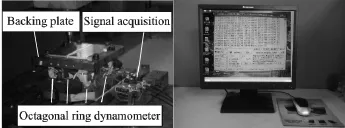
Fig.1 Experiment scheme
Before the test,octagonal ring dynamometer need to be calibrated.Octagonal ring dynamometer is fixed on the workbench for meeting requirement of force test.Check and adjust the workbench level of the octagonal ring dynamometer before the test.Workpiece is placed on the plate,butt line locates in the middle of the octagon ring dynamometer.Workpiece should be clamped before test.The tool with threaded pin of 3.0mm top diameter,3.0mm long,and 12mm diameter scrolled shoulder is used in the process.
1.2Stress measurement
Due to the interior of the plate cannot be directly contacted,the sensor installed in the interior of the plate to measure stress and strain in the FSJ process is impossible.A fine hole which leads to the measure position will be punched in the workpiece using the fine puncturing technique,and then put thin guide rod into the fine hole.One end of thin guide rod contacts to measure position material of the place,the other end connects to the pressure sensor.As force acts on measure position material,it will transmit to the pressure sensor by thin guide rod.Therefore,stress and strain of specific points are measured. Three fine holes conducting in the three directions are punctured to test point(From butt surface 2.5mm,from surface 5mm,measured from right side)and thin guide rod is connected to the pressure sensor(See Fig.2)(To mount the sensor at the bottom of the workpiece,a corresponding shallow groove should be processed in the plate). The parameters 600r/min rotational speed,100mm/min feed speed and 2.5°tool tilt angle tool are used in the process.The threaded taper tool is shown in Fig.3.The workpiece is 10mm in thickness.
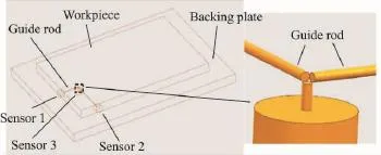
Fig.2 Assembly drawing
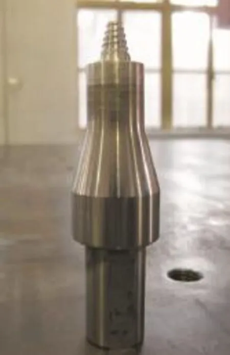
Fig.3 FSJ tool
2 Results and Discussion
2.1 Results of force measurement
Force curves obtained from the FSJ process which performed at 600r/min rotational speed,300mm/min feed speed,are shown in Fig 4.
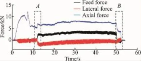
4 Force curves at rotational speed of 600r/min and feed speed of 300mm/min
From Fig.4it is clear that,the process is under the downward stage with the tool rotation,but without feed motion in 0—12s.The outputs of feed force and lateral force in the tool are small,almost zero at this stage.While the axial force value increases with time,it reaches the maximum value 12.5kN at 8s.As the heat gathers from the friction between tool and material,the material will gradually soften.After 8s,axial force decreases.It is because the push-up process can continue at the smaller axial force after materials soften enough.Material reaches the most softening state and the minimum axial force,5 kN,is obtained in the end point of the downward movement stage.Feed force,lateral force and axial force are suddenly increased(Point″A″in Fig. 4)at 12swhen the tool starts feeding.This is due to the tools move from an material softened sufficiently area to the material softened insufficient area at the beginning of feed.Some seconds later,the process enters into stable joining stage that the forces become stabilized and its fluctuation amplitude is small.Feed force and lateral force are small,2kN,-1kN,respectively,and the axial force is 7kN.It is close to the ending of the process(about 50s),the tool gradually pulls up and then completes the FSJ process.Axial force,feed force and lateral force are quickly reduced to zero in this process(Point″B″in Fig.4). Finally,a″keyhole″is left in the area where the tool uprooted.
The joining process is performed at rotational speed of 600r/min and feed speed of 400mm/min,and force curves can be obtained as shown in Fig 5.
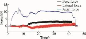
Force curves at rotational speed of 600r/min and feed speed of 400mm/min
Feed force,lateral force and axial force in Figs.4,5are compared respectively in Fig.6.In Fig.6,″600/300″represents ratational speed of 600r/min and feed speed of 300mm/min,″600/ 400″represents rotational speed of 600r/min and feed speed of 400mm/min.It is clear that feed force,lateral force and axial force at different feed speed substantially the same at downuard stage. The downward stage is basically the same at the same speed under different FSJ processes.In the stable joining stage,high feed speed results in small feed force and lateral force.But the same trend cannot get on axial force and high feed speed results in large feed force in the stable joining process.
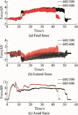
Comparison chart of feed,lateral and axial forces
2.2 Stress measurement and simulation

Stress curves at rotational speed of 600r/min and feed speed of 100mm/min
Stresses that measured by sensors 1,2and 3 at ratational speed of 600r/min and feed speed of 100mm/min in Fig.2are collected as shown in Fig.7.The pin is gradually close to the measuring point as the forward movement of the tool,and stresses in three directions of force measure point begin to fluctuation rise,but the amplitude is small.This is because the force transmitted to the measuring point is increased gradually as the tool constant moves to force a measuring point. However,because the tool is far away from the measuring point,the increase amplitude is small,so does the stress.As the joining process continues,the tool constantly closes to the measuringpoint.While the tool immediate contacts with the measure point,the stress increases to maximum value rapidly.This is because the material experiences severe plastic deformation in the measuring point.After the stress reaches the maximum value,it will be dropped rapidly.The heat generated by friction between tool and material softens the material in measuring area,so the stress decreases.In the last stage of the FSJ process,the tool is pulled out from the plate,and the testing process complets.Therefore,the maximum stress in the curves is the stress of the measure point.Stress in feed directionδxis 40.2MPa,stress in the direction that perpendicular to butt faceδyis 34.1MPa and stress in the direction that perpendicular to surfaceδzis 18.7MPa.
The plan stress in the FSJ process is analyzed by numerical simulation method.In the simulation,joint formation is considered as a plastic deformation process.The material characteristic is related to temperature.Friction between shoulder and material is defined to contact friction 0.3. Constitutive relations of flow stress and strain,and temperature and strain of finite element model are established by Coulomb friction law and Levy-Mises yield criterion.And using Deform finite element software,the FSJ process is simulated.The grid size is set to 0.2mm and shoulder angle of the tool is set to 2.5°during the simulation process.The finite element model is shown in Fig.8.The parameters are set to rotational speed of 600r/min and the feed speed of 100mm/min.The results are shown in Fig.9.

Fig.8 Numerical simulation of FSJ
It is clear that stress distribution is not symmetric in Fig.9(a).The simulation stress value of measure pointδ1is 57.83MPa in Fig.9(b). Stress in three directions are measured in the FSJ process.Therefore,the test stress value should be expressed
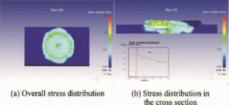
Fig.9 Stress distribution
Comparing the simulation stress valueδ1and the test stress valueδ2,the test stress value is close to the simulation stress value,but slightly less than the numerical simulation stress value. The mainly reason is that the connection between the rod and the pressure sensor is not tight enough.And the hole is slightly larger than the diameter of the rod.Therefore,the stress value transmitted to pressure sensor is slightly smaller. Considering a certain error range,test and numerical simulation can authenticate each other,both test stress value and numerical simulation stress value are credible.
3 Conclusions
(1)In the downward stage of the process,feed force and lateral force in the tool are small,almost zero,and the maximum axial force can reach 12.5kN.In the stable joining stage,the forces acting on the tool become stabilized.
(2)Compared with the low speed,high feed speed leads to small feed force and small lateral force,but large feed force in the stable joining process.
(3)The stresses of the measuring points are obtained that stress in feed direction is 40.2MPa,stress in direction perpendicular to butt face is 34.1MPa and stress in direction perpendicular to surface is 18.7MPa.
(4)The simulation stress value of measure point is 57.83MPa.Experiment and numerical simulationcan authenticate each other.Both experimental stress value and numerical simulation stress value are credible.
Acknowledgements
The work was supported by the National Natural Science Foundation of China(51175255),the Funding of Jiangsu Innovation Program for Graduate Education(CXZZ13_ 0152),and the Fundamental Research Funds for the Central Universities in P.R.China.
References:
[1] THOMAS W M.Friction stir butt welding:International patent PCT/GB92/02203[P].1991-12-06.
[2] MISHRA R S,MA Z Y.Friction stir welding and processing[J].Materials Science and Engineering,2005,50(1):13-58.
[3] DENG Yongfang,ZUO Dunwen,SONG Bo.Eccentric extrusion flow model of friction stir welding[J]. Transactions of the China Welding Institution,2014,34(12):41-45.(in Chinese)
[4] CUI G R,MA Z Y,LI S X.The origin of non-uniform microstructure and its effects on the mechanical properties of a friction stir processed Al-Mg alloy[J].Acta Materialia,2009,57(19):5718-5729.
[5] MCNELLEY T R,SWAMINATHAN S,SU J Q. Recrystallization mechanisms during friction stir welding/processing of alumimum alloys[J].Scripta Materialia,2008,58(5):349-354.
[6] SORENSEN C D,STAHL A.Experimental measurements of load distributions on friction stir weld pin tools[J].Metallurgical and Materials Transactions B,2007,38(3):451-459.
[7] KUMAR K,KAILAS S V.On the role of axial load and the effect of interface position on the tensile strength of a friction stir welded aluminium alloy[J]. Materials and Design,2008,29(4):791-797.
[8] ELANGOVAN K,BALASUBRAMANIAN V,VALLIAPPAN M.Influences of tool pin profile and axial force on the formation of friction stir processing zone in AA6061aluminium alloy[J].Int J Adv Manuf Technol,2008,38(3):285-295.
[9] CRAWFORD R,COOK G E,STRAUSSL A M,et al.Experimental defect analysis and force prediction simulation of high weld pitch friction stir welding[J].Science and Technology of Welding and Joining,2006,11(6):657-665.
[10]WANG Xijing,WANG Zhongke,HAN Daobin,et al. Measurements and analysis of onward force on stir-pin in FSW process[J].Transactions of the China Welding Institution,2010,31(4):1-4.(in Chinese)
[11]WANG Xijing,GUO Ruijie,CHEN Shujin,et al. Calculating and measuring of heating power of friction stir welding[J].Transactions of the China Welding Institution,2004,25(4):93-95.(in Chinese)
[12]ARORA A,DEBROY T,BHADESHIA H K D H. Back-of-the-envelope calculations in friction stir welding:velocities,peak temperature,torque,and hardness[J].Acta Materialia,2011,59(5):2020-2028.
[13]BUFFA G,HUA J,SHIVPURI R,et al.A continuum based FEM model for friction stir welding—Model development[J].Materials Science and Engineering A,2006,419(1/2):389-396.
Dr.Deng Yongfangis currently a lecturer in Institute of Engineering and Research at Jiangxi University of Science and Technology.He received his Ph.D.degree in Nanjing University of Aeronautics and Astronautics.His research interests include friction stir joining and milling.
Dr.Zuo Dunwenis currently aprofessor in College of Mechanical &Electrical Engineering at Nanjing University of Aeronautics and Astronautics.He received his Ph.D.degree in Kumamoto University.His research interests include friction stir joining and milling.
Mr.Song Bo is currently a Ph.D.candidate in College of Mechanical &Electrical Engineering at Nanjing University of Aeronautics and Astronautics.His research interests include friction stir joining and milling.
(Executive Editor:Xu Chengting)
TG404 Document code:A Article ID:1005-1120(2016)02-0237-06
*Corresponding author,E-mail address:zuodw@nuaa.edu.cn.
How to cite this article:Deng Yongfang,Zuo Dunwen,Song Bo.Forces and stress during friction stir joining of 2024aluminum alloy[J].Trans.Nanjing Univ.Aero.Astro.,2016,33(2):237-242.
http://dx.doi.org/10.16356/j.1005-1120.2016.02.237
杂志排行
Transactions of Nanjing University of Aeronautics and Astronautics的其它文章
- Jet Noise Reduction of Double-Mixing Exhaust System
- Grey Incidence Analysis Applied to Civil Aircraft Customization Process
- Gas Flow Development Through Tandem Heat Exchangers Inside Exhaust Nozzle by Using Porous Medium Model
- Heat Transfer Coefficient of Film Cooling with Ellipse-Shaped Tab
- Optimal Control of Reinforced Plate Based on the Minimum Energy
- Numerical Analysis of Refueling Drogue Oscillation During Refueling Docking
