Heat Transfer Coefficient of Film Cooling with Ellipse-Shaped Tab
2016-09-14ZhengXianwuYangWeihua
Zheng Xianwu,Yang Weihua
1.China Aviation Powerplant Research Institute,Zhuzhou 412002,P.R.China;2.College of Energy and Power Engineering,Nanjing University of Aeronautics and Astronautics,Nanjing 210016,P.R.China(Received 16July 2015;revised 3November 2015;accepted 11December 2015)
Heat Transfer Coefficient of Film Cooling with Ellipse-Shaped Tab
Zheng Xianwu1,Yang Weihua2*
1.China Aviation Powerplant Research Institute,Zhuzhou 412002,P.R.China;
2.College of Energy and Power Engineering,Nanjing University of Aeronautics and Astronautics,Nanjing 210016,P.R.China
(Received 16July 2015;revised 3November 2015;accepted 11December 2015)
The enhanced cooling performance caused by ellipse-shaped tabs located at the outlet of the film cooling holes is conducted.Three covering ratios of ellipse-shaped tabs on film holes and four blowing ratios are studied. The results show that:(1)The heat transfer coefficient ratio is higher than that without tab,indicating that the mixing of mainstream and coolant jet provides a better coverage film on the cooling wall,but increases the local turbulence production which enhances the heat transfer coefficient;(2)When the ellipse-shaped tabs are located at the film hole outlet,there is a larger pressure drop with the ellipse tab relative to the no-tab case.Thus,the discharge coefficient with ellipse tab is lower than that without tab.
energy and power engineering;turbine machine;ellipse-shaped tab;film cooling
0 Introduction
Advanced gas turbine engines operate at high temperature to improve thermal efficiency and power output.As the turbine inlet temperature increases,the heat transferred to the turbine blades also increases.The level and variation in the temperature within the blade material must be limited to achieve reasonable durability goals.Because the operating temperature of turbine blade is far above the permissible metal temperature,there is a need to cool the blade for safe operation.Film cooling is one of the most effectively cooling technologies used to cool the turbine blade in the turbine engine.
Film cooling has been widely studied in the past 40years.Goldstein[1]presented a review of all literature prior to 1971on flat surface film cooling.He presented the effects of various geometrical and flow parameters affecting film cooling.Refs.[2—6]studied the effects of blowing ratio,boundary layer displacement thickness to film hole diameter ratio,and mainstream Reynolds number on the heat transfer characteristics of film cooling with a single row of film holes inclined at 35°along the mainstream direction.The heat transfer coefficient ratio decreases with increasing axial distance from the injection hole.A-bout 15-hole diameters downstream of injection,the film cooling effect disappears.Refs.[7—14]studied the film cooling performance with cylindrical injection holes.The influences of blowing ratio,main flow turbulence intensity or density ratio on heat transfer coefficient or adiabatic film cooling effectiveness distribution by varying hole aperture to length ratio,compound angle or interval between injection holes/rows are discussed.
However,as the rapid development of turbine engine technology,the traditional film cooling cannot adapt to the need cooling the advanced turbine blade[15,16].Thus,several new film cooling technologies enhancing the film cooling effec-tiveness have been developed in recent years. These technologies included compound angle injection[17-21],shaped holes[22-26],holes with struts[27],and so on.The investigation demonstrated that all the new film cooling technologies could effectively improve the film cooling performance.
Ekkad et al.[28]demonstrated the fact that a tab located at the outlet of film hole can effectively enhance the film cooling performance.The effects of tab locations on the film-cooling behavior were investigated.It was observed that placing the tabs along the upstream edge of the hole had the best performance.Nasir et al.[29]experimentally investigated the effect of triangularshaped tabs with different orientations(Parallel to the surface,oriented downwards at 45°,and oriented upwards at 45°)on the film cooling performance from a row of cylindrical holes.Results showed that the tabs oriented downwards provided the highest effectiveness at a blowing ratio of 0.56while the tabs oriented horizontally provided the highest film effectiveness at blowing ratios of 1.13and 1.7.Li et al.[30]made a numerical computation on cylindrical film holes with the additional of triangular tabs covering the upstream edge of the holes.Yang and Zhang[31]experimentally investigated the film cooling characteristics from a row of film holes with ridge-shaped tabs. Three covering ratios of ridge shaped tab on film hole and four blowing ratios were considered. The results showed that the presence of ridgeshaped tabs in the nearby region of the primary film cooling holes mitigates the primary vortices. The lower penetration of coolant jet provides an increment in the film cooling effectiveness and also enhances heat transfer coefficient over the baseline case.The ridge-shaped tabs provide enhancements in cooling effectiveness,but this is at the expense of larger pressure drop,especially for ridge-shaped tabs with bigger covering ratio.
As mentioned above,it can be seen that the most of the investigations have been studied the heat transfer characteristics of the film cooling on the basis of triangular-shaped tabs and ridgeshaped tabs.However,the film cooling characteristics of ellipse-shaped tab has not been studied at present.We aim to further understand the mechanism on improvement of film cooling effectiveness using ellipse-shaped tabs and explore the effect of ellipse-shaped tab covering ratios and blowing ratios on the film-cooling performance in this paper.
1 Experiment
1.1 Experimental setup
All experiments are performed in a low speed wind tunnel setup(Fig.1)which is described[32]. The mainstream and coolant stream are measured by orifice flow meter and buoyage flow meter,respectively.The experimental temperatures of mainstream and coolant steam are 80℃and 25℃,respectively.An infrared thermography system(TVS-2000MK)is used to measure the temperature of cooling wall.All measurement data of temperature are connected with a 8-channel HP34970Adata collection system.
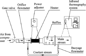
Fig.1 Experimental setup
The test sections(See Fig.2)is a rectangular channel with 245mm(Length)×200mm(Width)×100mm(Height)dimensions.The 0.02mm thick test plate is made of stainless steel foil with 135mm×200mm(Length and width)dimensions.The whole test plate is called cooling wall which can be heated by passing DC power.The surface of stainless steel foil is painted with black paint to assure an uniform emissivity of 0.96. Three T-type thermocouples acting as referencefor the infrared thermograph system are fastened on the rear of stainless steel foil with 502glue. Fig.3and Eq.(1)show the relationship between corrected infrared temperature and thermocouple date,respectively.
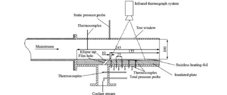
Fig.2 Schematic of test sections
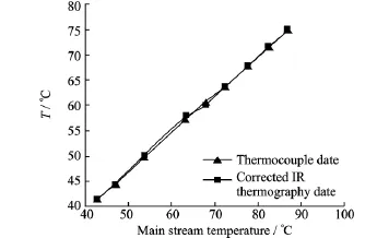
Fig.3 Relationship between corrected infrared temperature and thermocouple date
where T0is the infrared thermograph temperature and Tthe corrected infrared temperature.
The insulated plate is made of a 20mm thick Bakelite slab,which has a very low thermal conductivity of 0.06W/(m·°C).Three T-type thermocouples are glued on the outside of the insulated plate.
1.2 Experimental models
Fig.4shows the test plate with film holes geometry.Ten film holes of 6mm diameter in each row inclined at 35°in the mainstream direc-tion are machined in a Bakelite slab,and the length L,width S and heightδof the slab are 245mm,200mm and 20mm,respectively.The hole spacing between adjacent holes is 2-hole diameters for all the film holes.Measurements are performed for the middle five holes.The ellipseshaped tabs made of 0.2mm thick stainless steel are placed in the location,as shown in Figs.4(a),(b).There are three kinds of geometry dimensions for the ellipse-shaped tabs,and correspondingly the covering ratio Bof the tab on film hole is 0.107,0.214and 0.387,respectively.The geometry dimension of ellipse-shaped tabs and covering ratio are shown in Table 1.Therefore,there are four kinds of cases in this paper.Case 1 is the cylindrical hole with no tab.In case 2,the covering ratio Bis 0.107.In cases 3,4,the covering ratio Bis 0.214and 0.387,respectively.

Table1 Geometrical dimensions of test pieces
1.3 Definition of film cooling parameters
The blowing ratio is defined by

It can be rewritten as
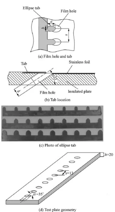
Fig.4 Film hole and ellipse-shaped tab

Adiabatic cooling effectivenessηis given as

Heat transfer coefficient ratio is defined as

where his the local heat transfer coefficient with film cooling and h0the heat transfer coefficient without film cooling on the flat surface.
When the coolant stream is injected on the flat surface from film hole,the film temperature Tfis a mixture of mainstream stream temperature Tmand coolant stream temperature Tc,that is the adiabatic wall temperature Taw.Therefore,the local heat transfer coefficient his defined as

where q=UI/Ais the heat flow rate of stainless foil when the foil being heated by passing DC power,I,Uand Aare electric current,voltage and heat area of stainless foil,respectively.With the desired voltage V and current I passing through the test plate,the heat flux qalong the surface of stainless foil can be calculated.Twis the wall temperature of stainless foil heated by passing DC power.The adiabatic wall temperature Tawcan be obtained by the definition of the cooling effectiveness Eq.(4).Substituting Eq.(4)into Eq.(6),the local heat transfer coefficient of film cooling becomes

The temperature distribution on the surface of stainless foil(heated or unheated)were recorded by an infrared thermography system operating in the middle IR band(8—14μm)of the infrared spectrum.The calculation method of the temperature map obtained from the infrared thermography system was described[30].During all of the experiments,the outer surface temperature of the insulated plate is between 25.5℃and 25℃while ambient temperature is approximately 24℃.The difference between ambient temperature and outer surface temperature of the insulated plate is less than 1.5℃.Therefore,the natural convection and the radiation losses from insulated plate are not taken into account.
The discharge coefficient is defined as the ratio of real mass flow rate mreto theoretic mass flow rate mththrough film holes.Real mass flow rate can be measured by experiment,and theoretic mass flow rate can be calculated assuming the isentropic flow from the coolant flow total pressure to the main stream static pressure.Therefore,for the incompressible fluid,the discharge coefficient can be defined aswhere p2is the coolant stream total pressure at the film hole inlet and p∞the mainstream static pressure,measured by coolant stream total pressure probe and mainstream pressure probe shown in Fig.5,respectively.

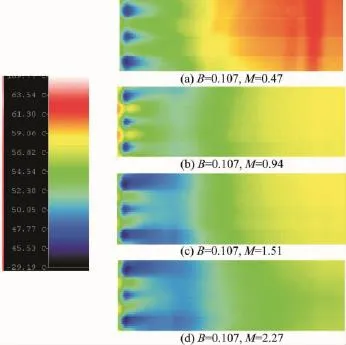
Fig.5 Effects of blowing ratio on temperature field of film cooling
According to Ref.[33],experimental uncertainties in heat transfer coefficient,film cooling effectiveness measurement were estimated to be about±10.6%and±4.2%,respectively.The individual uncertainty in mainstream temperature T∞was±0.4℃;Coolant temperature Tcwas ±0.2℃;Surface adiabatic wall temperature Tawwas±0.5℃.Experimental uncertainty in discharge coefficient measurements is about ±8.2%.
2 Results and Discussion
2.1 Temperature fields
Fig.5shows the effects of blowing ratio on film cooling adiabatic temperature fields at a given covering ratio B=0.107.Obviously,when the blowing ratio is lower(M=0.47),the coolant jets penetration to the mainstream is weaker,the phenomenon of coolant jet reattachment on the surface is not appeared,which leads to a higher temperature distribution on the surface.Under the same covering ratio B=0.107,the tempera-ture of cooling wall decreases with increasing blowing ratio from M=0.47to M=2.27,and the temperature distribution on the cooling wall is more and more uniform on the cooling wall.
Fig.6presents the effects of covering ratio B on the film cooling adiabatic temperature distributions on the cooling wall at a given blowing ratio M=1.51.The detailed distributions are shown for only the middle three holes although measurements are performed for the whole ten holes.For case 1(No tabs),the coolant can smoothly jet into the mainstream,which weakens the coolant reattachment on the cooling wall.That leads to a higher adiabatic temperature along the jet centerlines,with almost no cooling in between the holes for most of the cooling wall length(Fig.6(a)). In contrast to the no-tab case,the coolant jet penetration into the mainstream is effectively restrained by the tabs,and the coolant jet can more easily reattach to the cooling wall.After reattachment,the coolant jets spread laterally and fully spanwise coverage is observed in Fig.6(b).That is more evident with increasing covering ratio(See Figs.6(c),(d)).This fact is responsible for a lower adiabatic temperature of cooling wall. Under the same blowing ratio,not only is the adiabatic temperature decreased with the increase of covering ratio,but the temperature distribution ismore uniform.That shows that ellipse-shaped tab can effectively reduce the gas film cooling wall temperature.
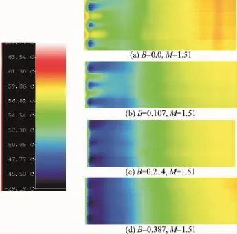
Fig.6 Effects of covering ratio on temperature field of film cooling
2.2 Heat transfer coefficients
Fig.7presents the effects of blowing ratio on the laterally averaged heat transfer coefficient ratio distributions on the cooling wall.The heat transfer coefficient h0is measured on the cooling wall without film holes.The heat transfer coefficient ratio is increased with increasing blowing ratio.In any case,the average heat transfer coefficient ratio is always greater than 1,which shows that the heat transfer coefficient is enhanced due to increasing turbulence produced by mixing of the coolant jets with the mainstream boundary layer.The increased turbulence locally enhances the heat transfer coefficient.However,there exists greatly different for the average heat transfer coefficient ratio distribution on the cooling wall between case 1and the other cases.For case 1,when the blowing ratio M>1,the heat transfer coefficient ratio almost keeps a constant 1.15. When the blowing ratio M>1.3,there exists a minimum heat transfer coefficient ratio in the region immediately downstream of the film hole. This can be explained by the action of the jet creating a stagnation region underneath the jet.The blowing ratio does not affect the presence of the stagnation.As the flow distance increases,the heat transfer coefficient ratio gradually increases to a peak where the coolant jet reattaches to the cooling wall.As the blowing ratio increases,the peak region becomes larger and larger.Further increase of blowing ratio(M>1.5)can cause the peak region to gradually shift downstream along the cooling wall.All the results agree well with Refs.[1—6].For cases 2—4,the coolant jet penetration into the mainstream is effectively restrained by the tabs,and the coolant jet can more easily reattach to the cooling wall,which causes the stagnation region immediately downstream of the film hole to disappear on the cooling wall and makes the peak location of heat transfer coefficient ratio shift forward to the film hole outlet.Thus,the maximum value location of heat transfer coefficient ratio is in the region immediately downstream of the film hole.The heat transfer coefficient ratio decreases with increasing axial distance from the film hole.However,when X/ d>4,the film cooling effect on the cooling wall will disappear,and the heat transfer coefficient ratio keeps a constant.For case 1,no film cooling effect location on the cooling wall is about 16-hole diameters downstream of film hole.Thus,we can know that the ellipse-shaped tab can enhance the heat transfer coefficient,on the other hand,it also shortens the film cooling distance on the cooling wall.
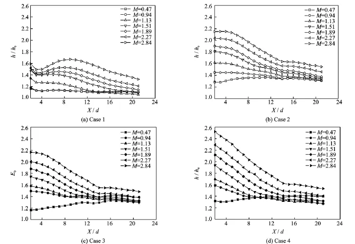
Fig.7 Effects of blowing ratio on averaged heat transfer coefficient
Fig.8presents the effects of covering ratios of ellipse-shaped tabs on the laterally averaged heat transfer coefficient ratio distributions on the cooling wall.Clearly,the heat transfer coefficient ratios of cases 2—4are higher than case 1.Especially,when the blowing ratio M>0.94,this kind of difference of heat transfer coefficient ratio increases with increasing blowing ratio.The effects of covering ratios on the heat transfer coefficient ratio vary with the blowing ratio.Each blowing ratio corresponds to a optimal covering ratio to obtain a maximum heat transfer coefficient ratio.At lower blowing ratio(M=0.47),the optimal covering ratio is 0.387.When the blowing ratio is 0.94,the optimal covering ratio is 0.214,and when the blowing ratio is greater than 1.5,the optimal covering ratio is 0.107. The reason to induce this kind of phenomenon is that when the blowing ratio is lower,the larger covering ratio can increase the coolant injection velocity from the film hole,and strengthen the jet injection turbulence levels inside the boundary layer due to the shear layer mixing.When the blowing ratio is greater than 1.5,the larger covering ratio will greatly increase the injection velocity from film hole,which makes the jet injection more difficult to reattach the cooling wall,and weakens the turbulence levels inside the boundary layer.
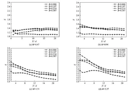
Fig.8 Effects of covering ratio on averaged heat transfer coefficient
2.3 Discharge coefficients
Fig.9shows the effects of covering ratio B and Re number on discharge coefficients of ellipse-shaped film holes.The Reynolds number is defined based on the coolant flow inlet velocity and diameter of film hole.Clearly,the discharge coefficient without ellipse-shaped tabs is far larger than that with ellipse-shaped tabs.The discharge coefficients are gradually decreased with increasing covering ratio B.Due to the fact that the discharge coefficient is proportional to the pressure drop of the film hole,there is a larger pressure drop with the ellipse-shaped tab relative to the notab case.As the coolant jet Reynolds number increases,the discharge coefficients for all cases increase.However,the ellipse-shaped tabs do enhance film cooling effectiveness and heat transfer coefficient,but the fact that ellipse-shaped tab at the outlet of film hole largely increases the larger pressure drop though the film hole can not be neglected.Therefore,when the optimum case is selected,the comprehensive effects of ellipseshaped tabs on the film cooling effectiveness,heat transfer coefficient and discharge coefficient should be considered.
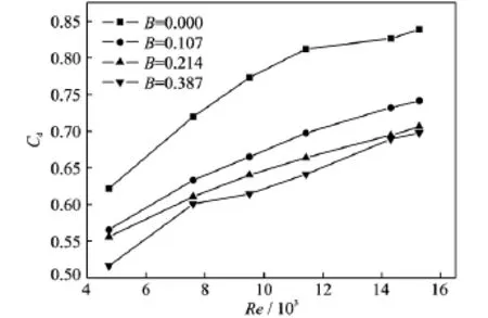
Fig.9 Effect of covering ratio on discharge coefficient(Ellipse)
2.4 Comparison between ellipse-shaped tab and triangle-shaped tab
At present,most of the investigations on tab film cooling have been focused on the triangularshaped tabs.In order to compare the difference of film cooling characteristics between the ellipse-shaped tab and equilateral triangle-shaped tab,an equilateral triangle-shaped tab which has all side equal was machined with the same material as the ellipse-shaped tab,and its covering ratio is 0.214.Fig.10shows the effects of tab configurations on film cooling effectiveness and heat transfer coefficient ratio at blowing ratio M=0.47and covering ratio B=0.214.From Fig.10(a),we can know that when X/d<10,the film cooling effectiveness of ellipse-shaped tab is higher than that of triangle-shaped tab,but when X/d>10,there is almost no difference between the two kinds of tabs.However,it can be known from Fig.10(b)that the heat transfer coefficient ratio of ellipse-shaped tab is higher than that of triangle-shaped tab,and the difference is larger and larger as the increase of X/d.Fig.11shows the comparison of discharge coefficients bewteen ellips-shaped tab and trangle-shaped tab.Clearly,the discharge coefficient of ellipsecient of ellipseshaped tab is higher than the triangle-shaped tab,which indicates that the pressure drop of film hole with ellipse-shaped tab is less than the that with triangle-shaped tab.Thus,it is reasonable to believe that the film cooling characteristics of ellipse-shaped tab is better than the triangle-shaped tab.
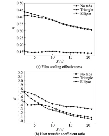
Fig.10 Comparison of film cooling effectiveness and heat transfer coefficient ratios between ellipseshaped tab and triangle tab at B=0.214,M= 0.47
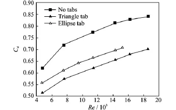
Fig.11 Comparison of discharge coefficients bewteen ellipse-shaped tab and triangle tab
3 Conclusions
The effects of ellipse-shaped tab placed at the film hole outlet on the film effectiveness,heat transfer coefficient ratio and discharger coefficient are investigated.Three different ellipse tab configurations are tested.The results are summarized as follows:
(1)The heat transfer coefficient ratio is higher for the ellipse-shaped tab at the film hole outlet than that without tab,indicating that the mixing of mainstream and coolant jet provides a better coverage film on the cooling wall,but increases the local turbulence production enhancing the heat transfer coefficient.
(2)The discharge coefficient is proportional to the pressure drop across the coolant hole. When the ellipse-shaped tabs are located at the film hole outlet,there is a larger pressure drop with the ellipse tab relative to the no-tab case. Thus,the discharge coefficient with ellipse tab is lower than that without tab.
(3)When the optimum case is selected,the comprehensive effects of ellipse-shaped tabs on the film cooling effectiveness,heat transfer coef-ficient and discharge coefficient should be considered.
(4)The ellipse tabs almost have the same film cooling effectiveness as the triangular tabs,but a larger heat transfer coefficient enhancement than triangular tabs.Thus,the heat flux to the wall will be higher if the film is hotter than the wall,but if the wall is hotter than the cooling film,the heat flux from the wall to the cooling film is also higher.At the same time,there is a large discharge coefficient for ellipse tabs than triangular tabs.Thus,it is difficult to specify which one is better between ellipse tabs and triangular tabs.When the optimum case is selected,the sum of all effects of ellipse-shaped tabs on the film cooling effectiveness,heat transfer coefficient and discharge coefficient should be considered.
Acknowledgement
This work was supported by the Research Program of the National Natural Science Foundation of China(51276088).
References:
[1] GOLDSTEIN R J.Film cooling[J].Advance in Heat Transfer,1971,7:321-379.
[2] AMMARI H D,HAY N,LAMPARD D.The effect of density ratio on the heat transfer coefficient from a film cooled flat plate[J].ASME J of Turbomachinery,1992,112:444-450.
[3] ERIKSEN V L,GOLDSTEIN R J.Heat transfer and film cooling following injection through inclined circular holes[J].ASME J Heat Transfer,1974,96:239-245.
[4] ERIKSEN V L.Film cooling effectiveness and heat transfer with injection through holes:NASA CR72991[R].1972.
[5] GOLDSTEIN R J,YOSHIDA T.The influence of a laminar boundary layer and laminar injection on film cooling performance[J].ASME J Heat Transfer,1982,104:355-362.
[6] LEISS C.Experimental investigation of film cooling with injection from a row of holes for the application to gas turbine blades[J].ASME J of Engineering forpower,1975,97:21-27.
[7] SCHMIDT D L,SEN B,BOGARD D G.Film cooling with compound angle hole:Heat transfer[J]. ASME J of Turbomachinery,1996,118:800-806.
[8] EKKAD S V,ZAPATA D,HAN J C.Film cooling effectiveness over a flat plate with air and CO2injection through compound angle holes using a transient liquid crystal image method[J].ASME J of Turbomachinery,1997,119:587-592.
[9] GOLDSTEIN R J,JIN P,OLSON R L.Film cooling effectiveness and heat/mass transfer coefficient downstream of one row of discrete holes[J].ASME J of Turbomachinery,1999,121:225-232.
[10]LIGRANI P M,ORTIZ A,JOSEPH S L,et al. Effects of embedded vortices on film-cooled turbulent boundary layers[J].ASME J of Turbomachinery,1994,111:71-89.
[11]MAYHEW J E,BAUGHN J W,BYERLEY A R. The effect of freestream turbulence on film cooling adiabatic effectiveness[J].Int J Heat &Fluid Flow,2003,24:669-679.
[12]AMMARI H D,HAY N,LAMPARD D.The effect of density ratio on the heat transfer coefficient from a film-cooled flat plate[J].ASME J of Turbomachinery,1996,112:444-450.
[13]JUNG J S,LEE J S.Effects of orientation angles on film cooling over a flat plate:Boundary layer temperature distributions and adiabatic film cooling effectiveness[J].ASME J of Turbomachinery,2000,122:153-160.
[14]BERHE M K,PATANKAR S V.Investigation of discrete hole film cooling parameters using curveplate models[J].ASME J of Turbomachinery,1999,121:793-803.
[15]YANG Weihua,ZHANG Jingzhou.Experimental study of HTC for film cooling of parallel-inlet holes[J].Transaction of Nanjing University of Aeronautics and Astronautics,2012,29(1):46-53.
[16]YANG Weihua,PENG Jianyong,CAO Jun,et al. Experimental study on cooling effectiveness of compound cooling configurations in reverse flow combustor[J].Journal of Nanjing University of Aeronautics &Astronautics,2012,44(6):769-774.(in Chinese)
[17]MCGOVERN K T,LEYLEK J H.A detailed analysis of film cooling physics:Part II-compound-angle injection with cylindrical holes[J].J Turbomach,2000,122(1):113-121.
[18]SCHMIDT D L,SEN B,BOGARD D G.Film cooling with compound angle holes:Adiabatic effectiveness[J].J Turbomach,1996,118(4):807-813.
[19]EKKAD S V,ZAPATA D,HAN J C.Film effectiveness over a flat surface with air and CO2injection through compound angle holes using a transient liquid crystal image method[J].J Turbomach,1997,119(3):587-593.
[20]LIGRANI P M,WIGLE J M,CIRIELLO S,et al. Film cooling from holes with compound angle orientations,Part 1:Results downstream of two staggered rows of holes with 3dspanwise spacing[J].J Heat Transfer,1994,116(2):341-352.
[21]LIGRANI P M,WIGLE J M,JACKSON S M.Film cooling from holes with compound angle orientations,Part 2:Results downstream of a single row of holes with 6dspanwise spacing[J].J Heat Transfer,1994,116(2):353-362.
[22]REISS H,BOLCS A.Experimental study of showerhead cooling on a cylinder comparing several configurations using cylindrical and shaped holes[J].ASME J Turbomach,2000,122:161-169.
[23]SCHMIDT D L,SEN B,BOGARD D G.Film cooling with compound angle holes:Adiabatic effectiveness[J].ASME J Turbomach,1996,118:807-813.
[24]SEN B,SCHMIDT D L,BOGARD D G.Film cooling with compound angle holes:Heat transfer[J]. ASME J Turbomach,1996,118:801-807.
[25]GRITSCH M,SCHULZ A,WITTIG S.Heat transfer coefficient measurements of film cooling holes with expanded slots:ASME Paper No.98-GT-28[R].New York:[s.n.],1998.
[26]YAO Yu,ZHANG Jingzhou.Investigation on film cooling characteristics from a row of converging slot holes on flat plate[J].Science China Technological Science,2011,54(17):1793-1800.
[27]SHIH T I P,LIN Y L,CHYU M K,et al.Computations of film cooling from hole with struts ASME Paper No.99-GT-282[R].New York:[s.n.],1999.
[28]EKKAD S V,NASIR H,ACHARYA S.Film cooling on a flat surface with a single row of cylindrical angled holes:Effect of discrete tabs[C]∥Proceedings of 2000IMECE.Orlando,Florida:[s.n.],2000.
[29]NASIR H,ACHARYA S,EKKAD S.Improved film cooling from cylindrical angled holes with triangular tabs:Effect of tab orientations[J].Int J HeatFluid Flow,2003,24:657-668.
[30]LI Yongkang,ZHANG Jingzhou,YAO Yu.Numerical investigation on improvement of film cooling effectiveness using delta-shaped tabs[J].J Aerospace Power,2006,21:83-87.(in Chinese)
[31]YANG Chengfeng,ZHANG Jingzhou.Experimental investigation on film cooling characteristics from a row of holes with ridge-shaped tabs[J].Experimental Thermal and Fluid Science,2012,37:113-120.
[32]YANG Weihua,LIU Xue,LI Guohui,et al.Experimental investigation on heat transfer characteristics of film cooling using parallel-inlet holes[J].International Journal of Thermal Sciences,2012,60:32-40.
[33]HOLMAN J P.Experimental methods for engineerings[M].4th ed.New York:McGraw_Hill,1984.
Mr.Zheng Xianwu is an engineer in China Aviation Power Plant Research Institute.He received his M.S.degree in Nanjing University of Aeronautics and Astronautics,and his main research interest is the heat transfer of turbine blade.
Dr.Yang Weihua is a professor in Nanjing University of Aeronautics and Astronautics.He received his Ph.D.in Shanghai Jiao Tong University,and his main research interests are advanced heat transfer and thermal protection technology of turbine blade.
(Executive Editor:Xu Chengting)
V231.1 Document code:A Article ID:1005-1120(2016)02-0155-11
*Corresponding author,E-mail address:yangwh-sjtu@163.com.
How to cite this article:Zheng Xianwu,Yang Weihua.Heat transfer coefficient of film cooling with ellipse-shaped tab[J]. Trans.Nanjing Univ.Aero.Astro.,2016,33(2):155-165.
http://dx.doi.org/10.16356/j.1005-1120.2016.02.155
杂志排行
Transactions of Nanjing University of Aeronautics and Astronautics的其它文章
- Jet Noise Reduction of Double-Mixing Exhaust System
- Grey Incidence Analysis Applied to Civil Aircraft Customization Process
- Gas Flow Development Through Tandem Heat Exchangers Inside Exhaust Nozzle by Using Porous Medium Model
- Optimal Control of Reinforced Plate Based on the Minimum Energy
- Numerical Analysis of Refueling Drogue Oscillation During Refueling Docking
- Experimental Analysis of A Cooling System for Wind-Driven Generator Stator
