Occupant Restraint System Simulation and Optimization Based on TESW
2016-09-14TianSheng
Tian Sheng
School of Civil Engineering and Transportation,South China University of Technology,Guangzhou 510640,P.R.China(Received 25December 2014;revised 27April 2015;accepted 8May 2015)
Occupant Restraint System Simulation and Optimization Based on TESW
Tian Sheng*
School of Civil Engineering and Transportation,South China University of Technology,Guangzhou 510640,P.R.China
(Received 25December 2014;revised 27April 2015;accepted 8May 2015)
Integrated into the development process of a chinese independent brand class sedan,optimization about occupant restraint system associated with dummy chest deceleration is studied.Based on this simulated vehicle deceleration and the target vehicle′s chest deceleration,tipped equivalent square wave(TESW)is calculated by combining the average stiffness kof occupant restraint system and the average free flight time t*from the existant CNCAP(China new car assessment program)tested cars.After proposing modeling regulations of occupant restraint system and establishing mathematical dynamic modelling(MADYMO)for occupant restraint system of the target vehicle,four optimization design parameters namely vent area A,load limit L,seat belt extension ratio Band pretension force Fare selected by weighted injury criteria(WIC)rule and the first-order response surface method. The four parameters have been optimized by using orthogonal test design of four factors with five levels and the optimum combination A5L1B1F5has been chosen by range and variance analyses.The results show that occupant restraint system performance has been optimized and improved,while meeting the chest deceleration calculation peak based on TESW.
full frontal impact;tipped equivalent square wave;occupant restraint system
0 Introduction
In the process of full frontal impact,some scholars,engineers and technicians′researches revealed that chest deceleration not only connected with the body structure,but also it was affected by occupant restraint system[1-3].In particular,the peak of dummy chest deceleration had a certain relationship among the occupant restraint system,the initial impact velocity,the body structure and occupant response[4-7].Thus Huang[8]assumed and proved that in the process of 100%frontal impact,dummy chest deceleration¨xoand body deceleration¨xvexisted following relationship:¨xo=Asin(ωt′+φ)+¨xv.According to the data of the similar structure of China new car assessment program(C-NCAP)tested star cars,Tian Sheng et al.[9]proposed to design target vehicle by equivalent dual trapezoids wave(EDTW)envelope curves and the average free flight time t*and the average occupant restraint system stiffness k,designing body structure based on EDTW and designing occupant restraint system based on tipped equivalent square wave(TESW)by using a fitting combination scheme. At the same time,Tian Sheng et al.[9]calculated chest deceleration based on equivalent square wave(ESW),TESW and EDTW comparably and found that chest deceleration peak based on TESW is most close to the actual one.On this basis,the occupant restraint system based on TESW will be optimally designed by simulation in the paper.
1 Calculation of Dummy Chest Deceleration
The better program curve of body deceleration is gained by simulation shown as Fig.1,which is lined with the principle of high in the front and low in the behind.According to Fig.1,when the deceleration is zero again,the moment is t7=76.50ms.
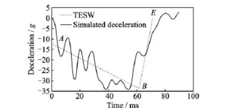
Fig.1 Vehicle simulation deceleration¨xvand TESW
The speed curve and displacement curve can be integrated from the vehicle deceleration curve respectively.we can see from the speed curve that when the speed is zero,the moment tmis 61.69ms,and when the moment t7is 76.50ms,the speed vt7is-1 580.63mm/s.We can also judge the maximum displacement C=494.79mm from the displacement curve,and calculate the waveform of TESW based on body deceleration in Fig.1.
When v0=50km/h and C=494.79mm,the centroid time tcis calculated as

Substituting v0=50km/h,tc=35.62ms and tm=61.69ms into the Eqs.(2),(3),respectively,calculating

Substituting tm=61.69ms,¨xv(0)= -12.29gand¨xv(tm)=-33.61ginto Eq.(4),getting the slope of the line AB(s1)

The equation of AB line in Fig.2is:¨xv= -0.345 6t-12.29(0≤t≤61.69ms).If the average free flight time t*is 16.01ms in C-NCAP frontal crash test,the equation can also be expressed as¨xv=-0.345 6t′-17.82(0≤t′≤45.68ms),and¨xv(t*)=-17.82g.

Fig.2 TESW
Because vt7is-1 580.63mm/s,the velocity difference of rebound phaseΔvris -1 580.63mm/s.Calculating the end time trof body rebound based on TESW

Substituting tm=61.69ms,tr=71.28ms and¨xv(tm)=-33.61ginto Eq.(7),getting the slope of the line BE(s2)

The equation of BEline in Fig.2is:¨xv= 3.504 69t-249.81(61.69ms≤t≤71.28ms)or ¨xv=3.504 69t′-193.70(45.68ms≤t′≤55.27ms).
Therefore,the three key points of TESW waveform based on the simulated body deceleration are:A(0,-12.29g),(61.69ms,-33.61g)and E(71.28ms,0).The fitting TESW waveform is shown as Fig.2.
If k=0.122 6g mm-1(the average stiffness of existing similar structures star vehicle′s occupant restraint system),34.68s-1=0.034 68ms-1.
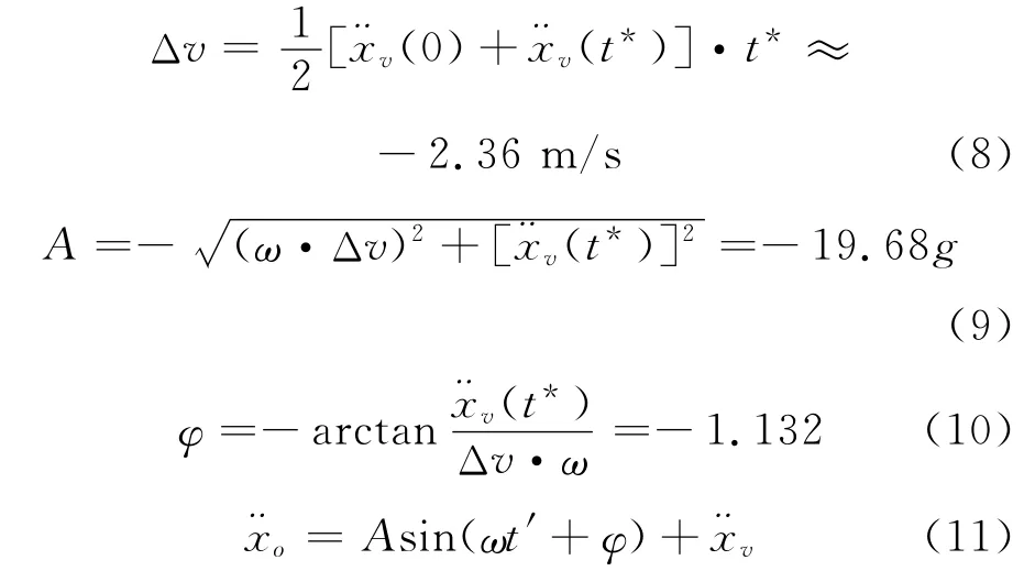
Calculating the shaded areaΔv referring to Fig.2shown as Eq.(8).In accordance with Eqs.(9),(10),respectively,calculating the amplitude Aand phase angleφ,then in accordance with Eq.(11)designing and calculating the dummy chest deceleration of target car.
Getting TESW through the simulated body deceleration curve,then chest deceleration is expressed as Eq.(12)based on TESW and shown as Fig.3.
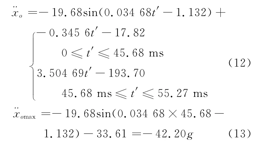
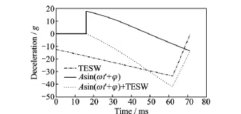
Fig.3 Dummy chest deceleration based on TESW from simulation
Thus,after calculating the average free flight time t*=16.01ms and the stiffness of occupant restraint systemk=0.122 6g mm-1through the star car of similar structure,the dummy chest deceleration of the target car has been calculated based on the simulated body deceleration.
2 Modeling of Occupant Restraint System
2.1 Modeling of interior
The accurate mathematical dynamic modeling(MADYMO)occupant restraint system of interior and components depends on the actual size and installation relationship,which can be selected from the general arrangement or design drawings. Because the installation of design products from different manufacture may be different,there will be some points in the modeling which need to pay strong attention to.The established multi-body(MB)model of the interior parts is shown as Fig. 4.
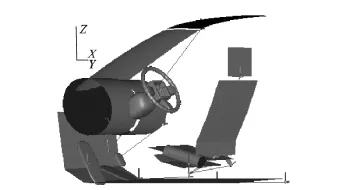
Fig.4 MB model of interior parts
2.2 Modeling of seat belt
The modeling and positioning of seat belt have an important impact on accuracy of the simulation results.Retractor,guide groove,height adjuster,D ring,buckle,anchor and other positional parameters determine the ribbon trend and connection of the seat belt model.Ribbon can be modeled by MB or the mix of MB and finite element(FE).The sliding of the seat belt in the dummy body surface can be simulated by MB and FE method,and the penetration effect of the seat belt fabric,which is embedded in the dummy body surface,can be simulated by orthotropic friction coefficient.The seat belt is modeled by MB and FE methods in this paper as shown in Figs.5,6.
2.3 Modeling of airbag
The FE airbag model includs the reference model and the initial model in MADYMO.Refer-ence model made by pre-treatment meshing software(e.g.Hypermesh)is the real shape of the airbag′s geometry without initial stress shown as Fig.7;Initial model is the airbag which has been folded shown as Fig.8,whose size and shape are the same as the ones of the real vehicle′airbag.In MADYMO,it will automatically search airbag′s reference model when initial model is inflated.
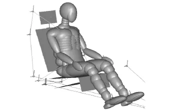
Fig.5 MB modeling of belt
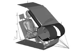
Fig.6 FE modeling of belt
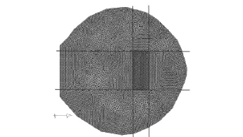
Fig.7 Airbag reference model
The fabric and hole materials of airbag need be set.While airbag chamber being set,we need to understand the parameters of the gas generator,such as ignition time(Switch),the gas mass flow(Mass-flow-rate)and gas ingredient(Gas).
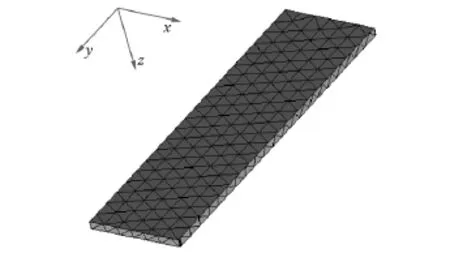
Fig.8 Airbag initial model
2.4 Dummy positioning
Accurate dummy positioning is very important to the simulation results in MADYMO. Commonly there are two dummy positioning methods:directly imput the measured location parameter values of the physical dummy before test(See Fig.9),or just exert the gravitational field to a dummy in the pre-simulation to make dummy and seat reach the static equilibrium state under the interaction of the parts(See Fig.10).In fact two methods are used in combination in the paper.
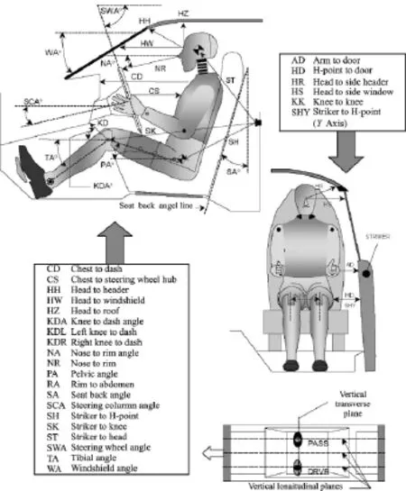
Fig.9 Dummy Position 1(Position data)
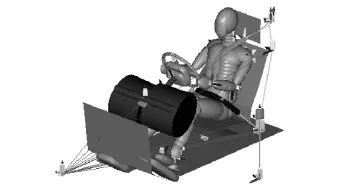
Fig.10 Dummy Position 2
3 Simulation and Optimization of Occupant Restraint System
The evaluation of occupant restraint system design depends on test scores of dummy.Weighted factors were introduced by Viano and Arepally[10]from general motors(GM)in 1990to evaluate the extent of dummy injury by integrating injury indexes together with weighted method and to fully evaluate the performance of occupant restraint system by using weighted injury criterion(WIC).Comprehensive evaluation index WIC is calculated by using head impact criteria(HIC),chest accelerations and compressions,and thigh′s forces.Weighted coefficient of each index in Eq.(14)shows that the injury extent which comes from the statistical analyses on a large number of accidents.The lower the WIC value is,the better the protect performance of occupant restraint system is.
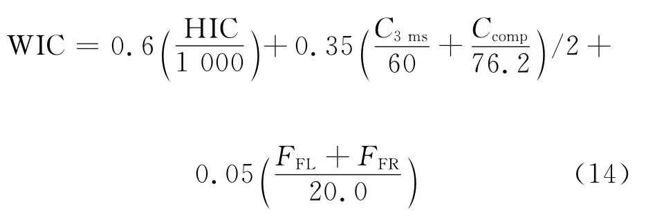
where HIC denotes comprehensive performance indexes of the head;C3msthe chest deceleration value during 3ms;Ccomp(mm)the chest compression;FFL(kN)the maximum axial force of the left thigh;and FFR(kN)the maximum axial force of the right thigh.
The first-order linear response surface model of WIC has been built by orthogonal experiment method to select four optimization design parame-ters,namely vent area A,load limit L,seat belt extension ratio Band pretension force Ffor occupant restraint system.
After selecting four parameters as the design variables of occupant restraint system,considering four changes of the initial value in the upper and lower symmetry which lead to five levels shown as Table 1.Therefore,this is a four factors and five levels orthogonal experimental design,selecting the orthogonal table L25(56).
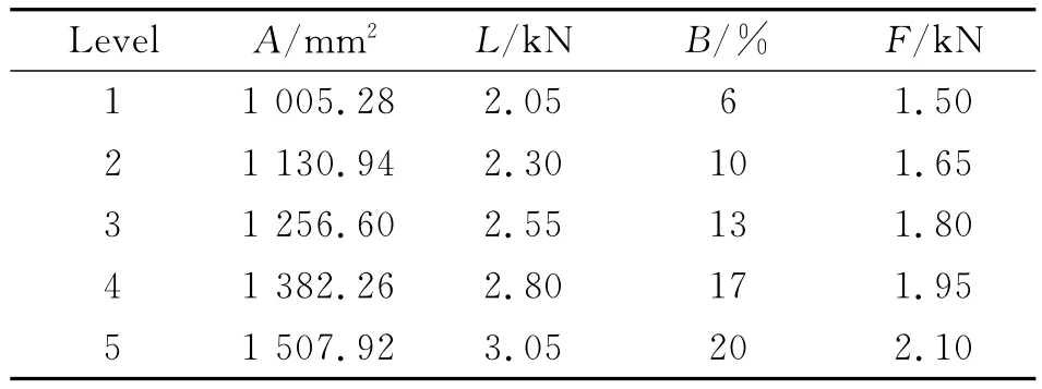
Table1 Four factors and five levels
It should be noted that dummy chest deceleration peak¨xomaxin x-direction introduced has been considered for the total occupant restraint system,including the steering wheel,so outputting the dummy HIC of the driver′s side,chest synthetic acceleration C3ms,chest compression Ccomp,the left thigh axial pressure FFL,and the right thigh axial pressure FFRin accordance with orthogonal experiment design of the four factors and five levels,then calculating WIC according to Eq.(14).In order to observe the peak deceleration ¨xomaxof dummy chest in x-direction whether meets -42.2g which is computed in the first part or not,in particular,the dummy chest peak deceleration¨xomaxin x-direction has been calculated.Increasing one program of initial value on the basis of the 25trials,the obtained results are shown as No.0test of Table 2when the four design parameters being taken the initial value.
If only take the minimum WIC(0.457 54)and absolute the minimum¨xomax(-41.489g)as the standard,we select No.22test combination in Table 2(A5L2B1F5).However,the chest deceleration peak¨xomaxhas been calculated(Equal to -42.2g)based on TESW in the first part of thispaper.Therefore,we choose the chest deceleration peak¨xomaxclose to-42.2gto verify ideas of this paper.But taking a combination of direct observation to the test results cannot completely guarantee the optimal combination,since we just make a part of the test.Therefore,we need to do the range and variance analyses,and make a comparative choice.
The optimal candidate solution is A4L4B2F5by variance analysis and the optimal candidate solution is A5L1B1F5by range analysis.Three optimal candidate solutions include A4L4B2F5(No.19 test),A5L2B1F5(No.22test),and A5L1B1F5,but A5L1B1F5combination does not appear in orthogonal test which need to remodel and simulate in MADYMO.The results of simulation are shown as Table 2,comparing with No.0,No.19 and No.22test.
Comparing the schemes in Table 2,in addition to decline of the major damage index value,such as WIC and HIC,¨xomaxshould be close to the calculated peak(-42.2g),too.Not only WIC and HIC of A5L1B1F5have been decreased,but also-42.283gis the closest to-42.2g(¨xomax). Although the left and right thigh axial forces of A5L1B1F5have been increased,the scores are still full scores(Full scores are 2points).Therefore,we choose A5L1B1F5as the final optimal program of occupant restraint systems(Shown as bold in Table 2).

Table2 Choosing scheme
4 Conclusions
(1)First,after the simulated and optimized body deceleration has been calculated to TESW,the dummy chest deceleration peak¨xomaxin x-direction is equal to-42.2gbased on TESW by a set of complete fitting combination design methodology of car full frontal impact safety.
(2)¨xomaxand WIC known as the objective functions identify the quantity to be minimized in order to optimize the occupant restraint system.
(3)The occupant restraint system is modeled by using MADYMO and modeling approach of the target vehicle is described,including interior,seat belt,airbag as well as the positioning of dummy.
(4)The four design parameters(vent area A,load limit L,seat belt extension ratio Band pretension force F)have been optimized by using four factors and five levels orthogonal experimental design.
(5)The calculation results show that the dummy injury WIC has been decreased by 8.67% and restraint system performance has been optimized and improved in the process of full frontal impact.
Acknowledgement
This work was supported by the National Science and Technology Support Program of China(2011BAG02B02).
References:
[1] AL-THAIRY H,WANG Y C.An assessment of the current Eurocode 1design methods for building structure steel columns under vehicle impact[J].Journal of Constructional Steel Research,2013,88(9):164-171.
[2] Hoffenson S,Frischknecht B D,Papalambros P Y. A market systems analysis of the U.S.sport utility vehicle market considering frontal crash safety technology and policy[J].Accident Analysis and Prevention,2013,50(1):943-954.
[3] AL-THAIRY H,WANG Y C.A simplified analytical method for predicting the critical velocity of vehicle impact on steel columns[J].Journal of Constructional Steel Research,2014,92(1):136-149.
[4] RYB G E,DISCHINGER P C,KLEINBERGER M,et al.Aortic injuries in newer vehicles[J].Accident Analysis and Prevention,2013,59(10):253-259.
[5] ADAM T,UNTAROIU C D.Identification of occupant posture using a Bayesian classification methodology to reduce the risk of injury in a collision[J]. Transportation Research Part C,2011,19(6):1078-1094.
[6] LEE E L,HAYES W C.Occupant accelerations and injury potential during an ambulance-to-curb impact[J].Forensic Science International,2014,237(4):6-10.
[7] KOPPEL S,MUIR C,BUDD L,et al.Parents′attitudes,knowledge and behaviours relating to safe child occupant travel[J].Accident Analysis and Prevention,2013,51(3):18-26.
[8] HUANG M.Vehicle crash mechanics[M].New York:CRA Press,2002:69-138.
[9] TIAN Sheng,HUANG Xiangdong,YANG Man,et al.Comparison and calculation of chest deceleration based on fitted wave for full frontal impact[J].Journal of South China University of Technology:Natural Science,2011,39(1):134-140.(in Chinese)
[10]VIANO D C,AREPALLY S.Assessing the safety performance of occupant restraint system:SAE Paper 902328[R].[S.l.]:SAE,1990.
Dr.Tian Shengis currently an associate professor of vehicle operation engineering in School of Civil Engineering and Transportation at South China University of Technology. He received his first degree and Ph.D.degree in South China University of Technology.His research interests are impact safety design for vehicle and traffic and transportation engineering.
(Executive Editor:Xu Chengting)
U461.91 Document code:A Article ID:1005-1120(2016)02-0224-07
*Corresponding author,E-mail address:shitian1@scut.edu.cn.
How to cite this article:Tian Sheng.Occupant restraint system simulation and optimization based on TESW[J].Trans. Nanjing Univ.Aero.Astro.,2016,33(2):224-230.
http://dx.doi.org/10.16356/j.1005-1120.2016.02.224
杂志排行
Transactions of Nanjing University of Aeronautics and Astronautics的其它文章
- Jet Noise Reduction of Double-Mixing Exhaust System
- Grey Incidence Analysis Applied to Civil Aircraft Customization Process
- Gas Flow Development Through Tandem Heat Exchangers Inside Exhaust Nozzle by Using Porous Medium Model
- Heat Transfer Coefficient of Film Cooling with Ellipse-Shaped Tab
- Optimal Control of Reinforced Plate Based on the Minimum Energy
- Numerical Analysis of Refueling Drogue Oscillation During Refueling Docking
