Experiment and simulation of foaming injection molding of polypropylene/nano-calcium carbonate composites by supercritical carbon dioxide☆
2016-05-29ZhenhaoXiJieChenTaoLiuLingZhaoLihShengTurng
Zhenhao Xi ,Jie Chen ,Tao Liu ,Ling Zhao ,*,Lih-Sheng Turng
1 State Key Laboratory of Chemical Engineering,East China University of Science and Technology,Shanghai 200237,China
2 Department of Mechanical Engineering,University of Wisconsin-Madison,WI 53706,USA
1.Introduction
Microcellular foams,a kind of polymeric foam with bubble sizes less than 10 μm and bubble densities larger than 108to 109cm-3,were introduced by Suh[1]in the 1980s to reduce material usage.However,maintaining the mechanical properties of microcellular polymeric foams as compared to solid materials still remains a major challenge today[2].Polymer composite foams,on the other hand,have been regarded as a promising alternative to their neat resin foams due to their enhanced mechanical properties,better thermal stability,improved barrier properties,and superior flame retardancy[3-5].Polypropylene/calcium carbonate(PP/CaCO3)composites are widely used owing to the excellent properties of PP along with the low price of CaCO3[6,7].The incorporation of CaCO3into PP not only increases the tensile strength of the composite,but also actsasan excellent crystal nucleation agent to enhance the impact strength of composites[8-11].This makes PP/CaCO3composites a promising candidate for overcoming the mechanical weakness of foamed PP alone for industrial applications.
Microcellular injection molding technology has been successfully commercialized by Trexel,Inc.[12,13]to injection mold microcellular foams which can further improve the mechanical and thermal properties,such as higher strength/weight ratios,enhanced toughness,and increased impact strength[14-18].Recently,an intensive research has been conducted on foaming processes employing environmentally benign blowing agents such as supercritical carbon dioxide(CO2)and nitrogen(N2).That is due to their unique properties such as being nonflammable,non-toxic,quick dissolving,and having high self-nucleating characteristics[19,20].Furthermore,blending supercritical fluid(SCF)in a polymer melt can effectively reduce the viscosity,the glass transition temperature and the interfacial tension[21,22].Thus,the foaming process can be operated at low temperatures and the degree of polymer degradation can be reduced[23,24].Since the properties of molded polymer composites are affected by the processing conditions and the amount of filler,a finer cell structure and more uniform cell size distribution can be achieved by controlling the foaming processing conditions[25,26].
For micro cellular foaming process,there are numerous models of bubble nucleation and growth[27-36],among which the classic nucleation model and diffusion-induced bubble grow th have been employed by the majority researchers for foaming process.By combining the bubble nucleation and growth model,Taki and co-workers numerically studied cell morphology the batch foamed PP by CO2[35,37].Different from batch foaming process with static polymer melt,the bubble nucleation and grow th in micro cellular injection molding undergo macroscopic melt polymer flow.Thus,an appropriate fluid model should be combined with the classic nucleation model and diffusion-induced bubble growth during the injection molding process.The Mu cell simulation function in the a CAE software Moldex 3D is a recent development of three dimensional prediction of final bubble morphology with finite volume method in micro cellular injection molding process,in which the capability of 3D Mucell prediction has been well validated with the experimental results of micro cellular injection molding of polypropylene with supercritical nitrogen[10,11,38,39].
In this work,microcellular injection molding of isotactic polypropylene/nano-CaCO3composites was performed to investigate the microstructures of microcellular foams.The effects of the processing conditions,including the nano-CaCO3w eight content,mold temperature,super-critical gas content,and injection speed,on the microstructures of microcells were studied.Then the Moldex 3D softw are was applied to simulate the microcellular injection molding process of neat polypropylene and polypropylene/nanocalcium carbonate composites respectively.
2.Experimental
2.1.Materials
Isotatic polypropylene(Pro-fax7523)with an average melt flow index(MFI)of 4.0 g per 10 min(230°C,21.6 N)was supplied by Basell Co.,America.The filler,nano-CaCO3without surfacetreatment waspurchased from Shanghai LingFeng Chemical Co.,China.The primary particle size of nano-CaCO3is about 100 to 200 μm.TYZON TPT used as titanate compatibilizer,was provided by Dorf Ketal Chemical LLC,America.The physical blow ing agent CO2(99.97%)was supplied by Airgas.Co.,USA.All other materials were used as received.
The iPP was melt compounded with different w eight contents of nano-CaCO3in a twin screw extruder(Leistritz,GmbH)at a screw speed of 50 r·min-1.The nano-CaCO3was organically pretreated with the titanate compatibilizer using the following process.First,2 ml TYZON TPT was dissolved into 500 ml toluene with stirring at 45°C for 4 h.Thereafter,200 g of nano-CaCO3was added into this solution with stirring for another 6 h.The mixture was filtrated with Buchner funnel and washed several times using toluene.The rest of solvent was removed in a fume cupboard.Before compounding,the PP resin and the pretreated nano-CaCO3powder were dried in a vacuum oven at 80°C for 12 h.For comparison,the neat PP for injection molding was also treated under the same process condition as the composites in the extruder.
2.2.Injection molding processing
The injection molding experiments were conducted on the injection molding machine(Arburg Allrounder 320)equipped with a MuCell SCF dosing system(Trexel,Inc.,Wilmington,MA).Supercritical carbon dioxide(ScCO2)was used as the physical blowing agents.The molding experiments were set to produce the standard ASTM-D638 tensile bars.The extruder barrel temperatures,from the hopper to the die,were set of 20,175,200,220,and 220°C,and the screw speed was 15 m·s-1.
Based on the experiment scheme as specified in Table 1,the iPP/nano-CaCO3composites with different contents of filler(2.5%and 5.0%)were injection molded for microcellular foams to investigate the effects of processing conditions(i.e.injection speed,mold temperature,and SCF weight percentage)on cell morphologies.A high CO2concentration was achieved by adjusting the pressure difference between the SCF outlet and the barrel[40].The w eight reduction was maintained at 15%for all the foamed parts,with proper control of the shot size.Also,the additional molding trial was made for solid parts at the same processing conditions with no CO2injection.

Table 1 Experimental design of foaming injection molding
2.3.Testing techniques
The micro-cellular structure of the molded parts was examined using a JEOL Neoscope Scanning electron microscopy(SEM)(Nikon Corp.)with an accelerating voltage of 10 kV.The SEM specimens(Fig.1)were taken from the middle of the molded tensile bars by fracturing after being immersed in liquid nitrogen for 10 min and then spurted with a Pd(palladium)coating for 45 s.The average cell sizes and cell densities were obtained from the SEM analysis by the Image-Pro Plus 6.0(Media Cybernetics,Silver Spring,MD)[21].The number average diameter of all of the cells in the micrograph,d,was estimated using the following equation,


Fig.1.Schematic of SEM specimen preparation.
where niwas the number of cells with a perimeter-equivalent diameter of di.
The cell density N0,defined as the number of cells per unit volume with respect to an unfoamed polymer,was determined as,

w here n was the number of cells in a given area,A was the area of interest.
3.Simulations by Moldex 3D
The Mucell simulation in the CAEs oft ware Moldex 3D is a significant development of three-dimensional prediction of final bubble morphology in micro cellular injection molding process recently,in which the capability of 3D Mucell prediction has been w ell validated with the experimental results of micro cellular injection molding of polypropylene with supercritical nitrogen.In this study,the Mucell simulations are carried out for micro cellular injection molding process of both iPP and iPP/nano-CaCO3composites with supercritical carbon dioxide.
In Mucell simulation by Moldex 3D,the polymer/gas mixture is always considered as a General New tonian compressible fluid during the micro cellular injection molding process,which can simplify the mathematically calculation.Therefore,the flow field can be expressed by mass balance,momentum balance and energy balance equations as follow s:
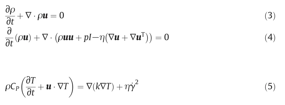
where ρ is the density of polymer,t is the time,u is the velocity vector,η is the viscosity,T is the temperature,CPis the specific heat and γ˙is the shear rate.
The bubble nucleation and grow th models developed by Taki for PP are employed in this study[35].A brief summarize of the model development is show n as follow s.
Radio of bubble growth for momentum balance equation

w here R is the bubble radius,PDand PCare the bubble and ambient pressure respectively,η is the viscosity and γ is the surface tension.
Mass balance at the shell of bubbledescribed by a diffusion equation

where c is the gas concentration,r is the distance to the center of bubble sphere,and D is the gas diffusion coefficient.
Mass balance at the interface of bubble

With the concentration gradient around the bubble

w here CRis the gas concentration on the w all of bubble while C is the one at infinity,and δ is the distance to the w all of bubble.
The Mass balance at the interface of bubble can be written as

Bubble nucleation rate

The average concentration of gas in polymer

The Zeldovich factor f0corrects among other things for the fact that some clusters that have reached the critical size still decay to smaller sizes.
In this study,all the universal parameters used in the simulation by Moldex 3D of injection foaming process for neat iPP and iPP/nano-CaCO3composites injection foaming with ScCO2were listed in Table 2,w here the CO2diffusion coefficient(D)and solubility coefficient(S)were tested by our lab using Magnetic Suspension Balance(MSB)[41],and the surface tension and Shreshold of nucleation Jshresholdmeasured by Taki with a small visual reactor[35,42].Besides that,modified cross model adopted to describe the rheological properties for neat PP melt and the composites was show n as follow s,w here η0is the zero-shear viscosity,n is the non-New tonian index,γ*is shear stress at the initial shear-thinning behavior,and B and Tbare the polymer nature constants.


Table 2 Input parameters for injection foaming simulation of iPP and iPP/nano-CaCO3 composites

Fig.2.SEM images of microcellular injection molded neat iPP.
4.Results and Discussion
4.1.Cellular structure
Typical SEM micrographs of microcellular structures for microcellular injection molded specimens of neat iPP and iPP/nano-CaCO3composites are show n in Figs.2 and 3,respectively.
4.1.1.Effect of dissolved CO2 concentration and back pressure
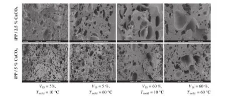
Fig.3.SEM images of microcellular injection molded iPP/nano-CaCO3 composites at LB=5%.
The cell morphologies for foamed neat iPP under three different dissolved CO2and back pressure levels are show n in three lines from top to the bottom.Comparing these three line,it can be clearly seen that the bubble size sequence is HB 7%<HB 5%<LB 5%,and the bubble density sequence is HB 7%>HB 5%>LB 5%.In foaming injection molding,the melt pressure of polymer/gas mixture is directly controlled by the back pressure,thus the pressure drop rate of melt is consequently affected by the back pressure.Although the pressure release rate for foaming is same at HB 7%and HB 5%,the nucleation energy barrier under high CO2concentration is lower and the nucleation supersaturation degree can be achieved faster than low CO2concentration,which results in a higher nucleation rate and bubble density under high CO2concentration.Meanwhile,as the bubble nucleation and grow th are the two competitive stages during foaming process,fast nucleation rate means the low bubble grow th rate,that leads to a smaller cell size under high CO2concentration.Thus,comparing the foaming process at HB 7%and LB 5%,both the gas pressure release rate and CO2concentration are much higher for HB 7%,then the bubble density is way larger and the bubble size is much smaller than those foamed at LB 5%under same injection speed and mold temperature.In addition,a certain degree of super saturation of dissolved gas,which is known as nucleation supersaturation degree,should be achieved before the first bubble nucleated during the foaming process.Higher pressure release rate or lower unsaturated degree of the dissolved gas before foaming would accelerate the achievement of nucleation supersaturation degree.Comparing the foaming process at HB 5%and LB 5%,the dissolved CO2under LB 5%in the saturate state as the degree of unsaturated is much lower,while the pressure drop release rate is higher under HB 5%.For foaming injection molding,as the pressure of polymer/gas would immediately reduced once the solution injected to the cavity,the pressure drop rate is relatively high,as a result,the nucleation supersaturation degree can be achieved faster under a high back pressure even then the low one with corresponding small degree of unsaturation.Therefore the setting of back pressure is the key point on controlling the final foam products for the microcellular injection.
4.1.2.Effect of mold temperature and injection speed
For each level of dissolved CO2concentration and back pressure,the cell morphology obtained from different injection speeds and mold temperatures were arranged from left to right.Notice that,the bubble size is larger while the bubbles density is lower under high mold temperature and high injection speed.It is due to that the cooling speed of melt under high mold temperature is slower than that under low mold temperature,and then the bubble can more fully grow accordingly.Although the temperature does not directly affect the bubble nucleation at the initial foaming stage,it is easy to be merged for the growing large bubbles under high mold temperature,which leads to a larger bubble size and a lower bubbles density.
As mentioned above,the pressure drop is very high since the pressure of melt would suddenly drop to ambient.But the injection speed can only affect the speed of the melt pushing forward,and has little effect on the pressure release rate for the melt already injected in to the cavity.However the injection speed obviously affects the fountain flow of polymer melt/bubble mixture.In a fountain flow,the bubble is firstly created at the front,and then pushed towards the w all of the cavity.Under low injection speed,the melt experience longer flow time,the bubbles formed in the fountain flow front will be continuously pushed to the wall and squeezed by the flow,inhibiting the bubble grow th and leading to a smaller bubble size.How ever,under high injection speed,the time of fountain flow is short,the bubble almost nucleated simultaneously at the end of filling.A lot of uniform large bubble would emerge resulting in a large bubble size.Meanwhile,the fountain flow bubble is an unstable flow,it is easy to create lots of thermal unstable site at the interface for cell nucleation,since the difference of CO2concentration and shear strength in different layers of flows.Therefore,foaming with low injection speed would results in a smaller bubble size and higher bubble density.
4.1.3.Effect of filler content
The effects of concentration of nano-CaCO3in iPP/nano-CaCO3composites on the cell morphology of foamed composites by micro cellular injection molding are shown in Fig.3.It is clear that,the cell size of composites foam is greatly reduced and the cell density increases by using the nano-CaCO3fillers for all the injection conditions.The cell size decreases with increasing filler loading and the cell density increases accordingly.It demonstrates that the nano-CaCO3is one of the perfect nucleation agents during the foaming process and the number of bubble nucleation can be enhanced by increasing the filler content.In fact,the cell morphologies obtained under HB 7%and HB 5%also show the same filler dependence.
4.2.Simulation for injection foaming of neat PP
For neat PP,the shear viscosity of melts accords with Modified cross model and the four model parameters implemented by Moldex 3D database,n, γ*,B and Tb,are 0.2916,24750 Pa,0.2219 Pa·s and 4913 K,respectively.The pre-exponential factor of nucleation rate f0for neat iPP is 3.5×10⁻²⁵and the correction factor for nucleation activation energy F is 0.014085.Both of that have also been published by Taki[35].Then,microcellular injection molding process of neat iPP has been simulated by Moldex 3D and the bubble morphology in surface layer and corelayer hasbeen predicted in detail wiped off the unfoamed layer.The typical simulated bubble morphology compared with experimental SEM micrograph of microcellular structures in surface layer and core layer for neat PP are show n in Fig.4.And the comparisons of the bubble size and bubble density of injection molded iPP by experimental and Moldex 3D simulated results for trials 1-4 and 9-12 are show n in Figs.5 and 6,respectively.
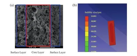
Fig.4.Experimental and simulated cell size distribution for neat PP at trail 1 condition,(a)Experimental SEM image,(b)Simulated result by Moldex 3D.
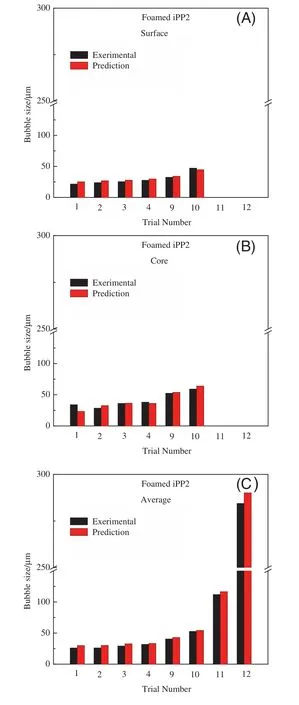
Fig.5.Comparison of bubble size between the experimental and simulated results for foamed iPP,(A)surface layer;(B)core layer;(C)average.

Fig.6.Comparison of bubble density between experimental and simulated results for foamed iPP,(A)surface layer;(B)core layer;(C)average.
It is clear that the cell morphology simulated has similar inhomogeneity to experimental result during the microcellular injection molding process which can be generally divided into two layers barring the unfoamed parts,the surface layer and the core layer.That is due to the thermodynamic instability,shear effect and cooling-solidification phenomenon.During the injection foaming process,the polymer melt close to the mold surface is intensively affected by shear effect,so the bubble size on the surface layer of molded samples is smaller with fast cooling rate and short bubble grow th time;while the cell has large size in core layer which maintains a longstanding molten state for grow th and low shear stress.Both of the experimental and simulated bubble morphology show s an obvious stratified structure with bubble size decreasing in sample's thickness direction from center to the surface layer.
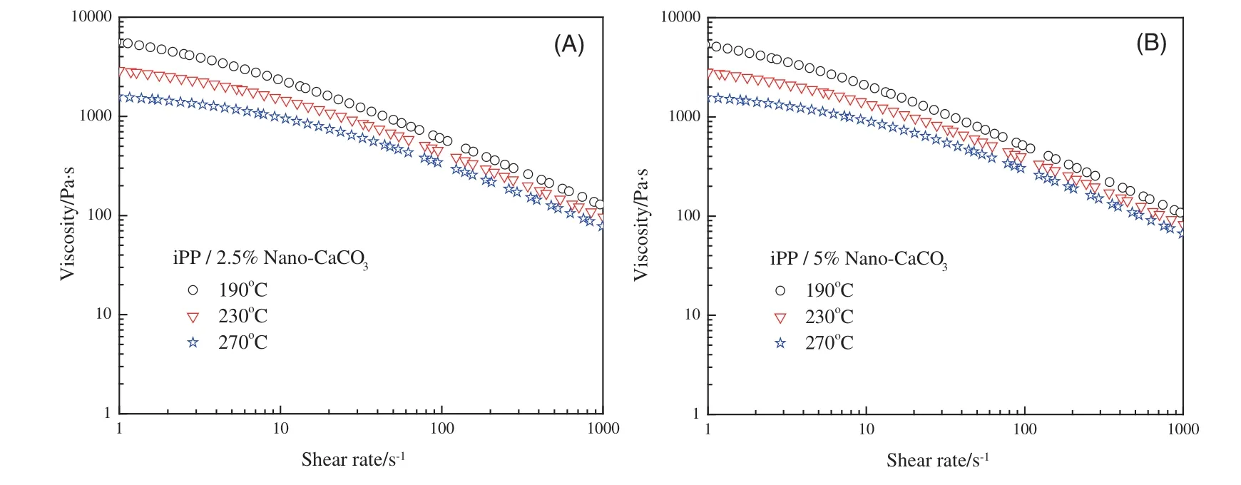
Fig.7.Shear viscosity of iPP/nano-CaCO3 composites versus shear rate,(A)iPP/2.5%nano-CaCO3;(B)iPP/5%nano-CaCO3.
The figures show that the values of bubble size both in surface layer and core layer,as well as the bubble density,of injection molded iPP by Moldex 3D simulated results are very close to the experimental ones for trials.The average relative deviation between the experimental and simulated results of the bubble size is 5.38%and the one of the bubble density is 9.13%.It indicates that the flow field,the bubble nucleation and the bubble grow th can be integrated w ell in Moldex 3D by using finite volume method.Moldex 3D software with appropriate input parameters can be used to w ell predict the distribution of flow field,bubble size and bubble density during the micro cellular injection molding process.
4.3.Simulation for injection foaming of iPP/nano-CaCO3 composites
For iPP/nano-CaCO3composites with different filler contents,the shear viscosity of melts was measured using a TA-ARES rheometer by dynamic frequency sw eep tests under a nitrogen gas purge.The frequency dependences of the shear viscosity for iPP/nano-CaCO3composites at different temperatures are show n in Fig.7.Then,the rheological parameters for modified cross model,n,γ*,B and Tb, fitting by the rheological data can be obtained listed in Table 3.How ever,the pre-exponential factor of nucleation rate f0for iPP/nano-CaCO3composites and the corresponding correction factor for nucleation activation energy F are unknown as the bubble nucleation being the heterogeneous nucleation.The two parameters of nucleation,also show n in Table 3,are established through nonlinear regression of the experimental bubble size and bubble density data for iPP/2.5%nano-CaCO3and iPP/5%nano-CaCO3,respectively.
Compared to the parameters of homogeneous nucleation for neat PP,the correction factor for nucleation activation energy F for iPP/nano-CaCO3 composites clearly decreases while the preexponential factor of nucleation rate f0increases as the fillercompounded.With the increasing of filler content,the F value decreases further while the f0increases concurrently.That is due to the nano-scale filler,nano-CaCO3is a perfect nucleation agents during the foaming process which can effectively reduce the nucleation activation energy for supercritical carbon dioxide.Also,the form of nucleation changes from homogeneous nucleation to heterogeneous nucleation.Thus,more nano-CaCO3filled into the polymer/gas mixture distinctly leads to easier nucleation for the blow agent.Meanwhile,the bubble size and bubble density are also observably affected correspondingly.

Table 3 Rheological and nucleation parameters for iPP/nano-CaCO3 composites
The comparisons of the bubble size and bubble density of injection molded iPP/nano-CaCO3composites by experimental and Moldex 3D simulated results for trials 1-4 and 9-12 are show n in Figs.8 to 11,respectively.The figures also show that the values of bubble size,as w ell as the bubble density,both in surface layer and core layer of microcellular foamed iPP/nano-CaCO3composites simulated by Moldex 3D are basically close to the experimental results for all trials.For iPP/2.5%nano-CaCO3,the average relative deviation between the experimental and simulated results of the bubble size is 3.28%and the one of bubble density is 6.65%,while the ones for iPP/5%nano-CaCO3are 3.05%and 14.3%,respectively.As the average relative deviations are less than 15%,it indicates that the pre-exponential factor of nucleation rate f0and corresponding correction factor for nucleation activation energy F obtained through regression for iPP/nano-CaCO3composites can be used to predict the microcellular injection molding process by Moldex 3D.
5.Conclusions
Microcellular injection molding of neat isotactic polypropylene(iPP)and isotactic polypropylene/nano-calcium carbonate composites(iPP/nano-CaCO3)were performed using supercritical carbon dioxide(Sc CO2)as the physical blow ing agent.The influence of filler content and operating conditions on microstructure morphology of molded iPP/nano-CaCO3microcellular samples was studied systematically.The results show that the bubble size of the microcellular samples,as w ell as the bubble density,could be effectively affected by the dissolved CO2concentration and back pressure.A lower nucleation energy barrier and faster super saturation with high nucleation rate will result in a smaller bubble size and higher bubble density under higher CO2concentration.Also,the high pressure drop release rate controlled by setting of back pressure is also a w ay to obtain the small cell size with high bubble density.Besides that,a smaller bubble size and higher bubble density can be achieved at low mold temperature and injection speed results in a smaller bubble size and higher bubble density.Furthermore,the filler,nano-CaCO3,is good for nucleation during the foaming process and the cell size is greatly reduced and the cell density increases with the cooperation of nano-CaCO3fillers.That has a deferred effect on impact crack and enhances the impact strength.
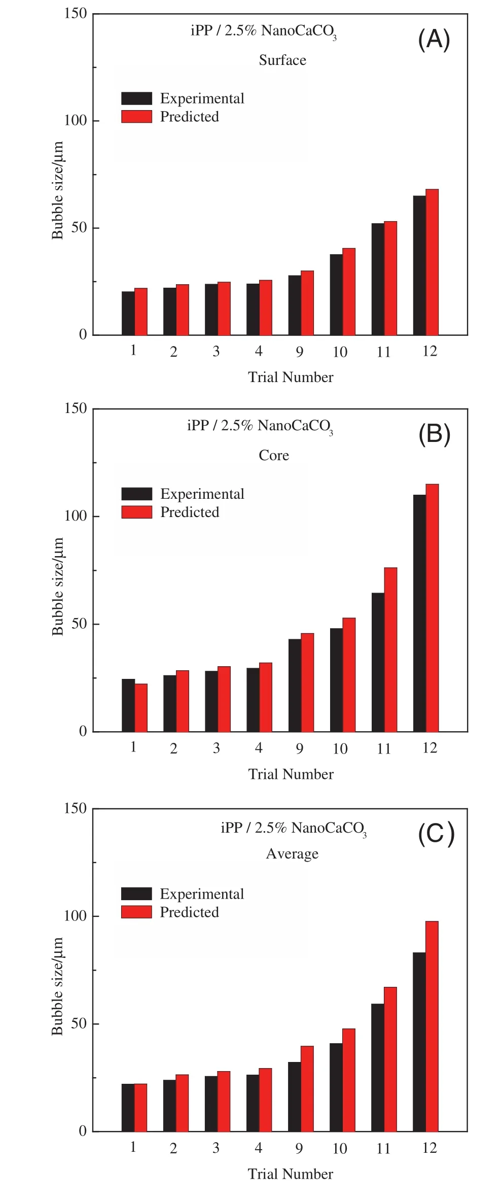
Fig.8.Comparison of bubble size between the experimental and simulated results for foamed iPP/2.5%nano-CaCO3,(A)surface layer;(B)core layer;(C)average.
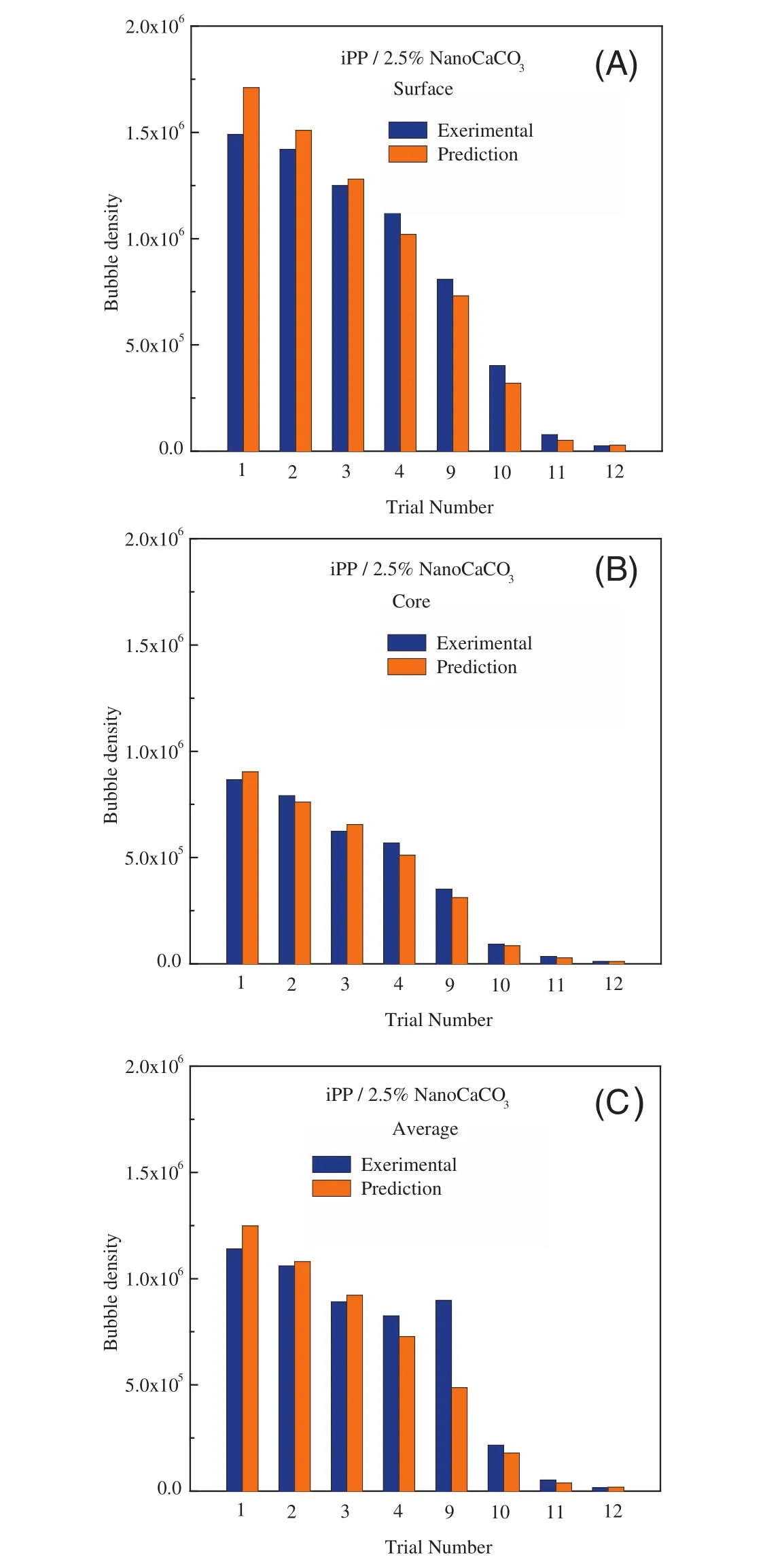
Fig.9.Comparison of bubble density between the experimental and simulated results for foamed iPP/2.5%nano-CaCO3,(A)surface layer;(B)core layer;(C)average.

Fig.10.Comparison of bubble size between the experimental and simulated results for foamed iPP/5%nano-CaCO3,(A)surface layer;(B)core layer;(C)average.
By using Moldex 3D,the microcellular injection molding processes of neat iPP were simulated.The simulated results of bubble morphology compared to the experimental ones,indicates that the microcellular injection molding process including the flow field,the bubble nucleation and the bubble grow th can be predicted w ell in Moldex 3D by using finite volume method with experienced parameters.How ever,for iPP/nano-CaCO3composites,the correction factor for nucleation activation energy F decreases as the filler compounded while the pre-exponential factor of nucleation rate f0increases.The values of F and f0,obtained by nonlinear regression on the experimental bubble size and density distribution,are 0.013 and 3.5×10⁻²¹for iPP/2.5%nano-CaCO3composites,resp ectively;while the ones are 0.011 and 3.5×10⁻¹⁹for iPP/5%nano-CaCO3composites,respectively.These parameters can be used to predict the microcellular injection molding process for iPP/nano-CaCO3composites by Moldex 3D.
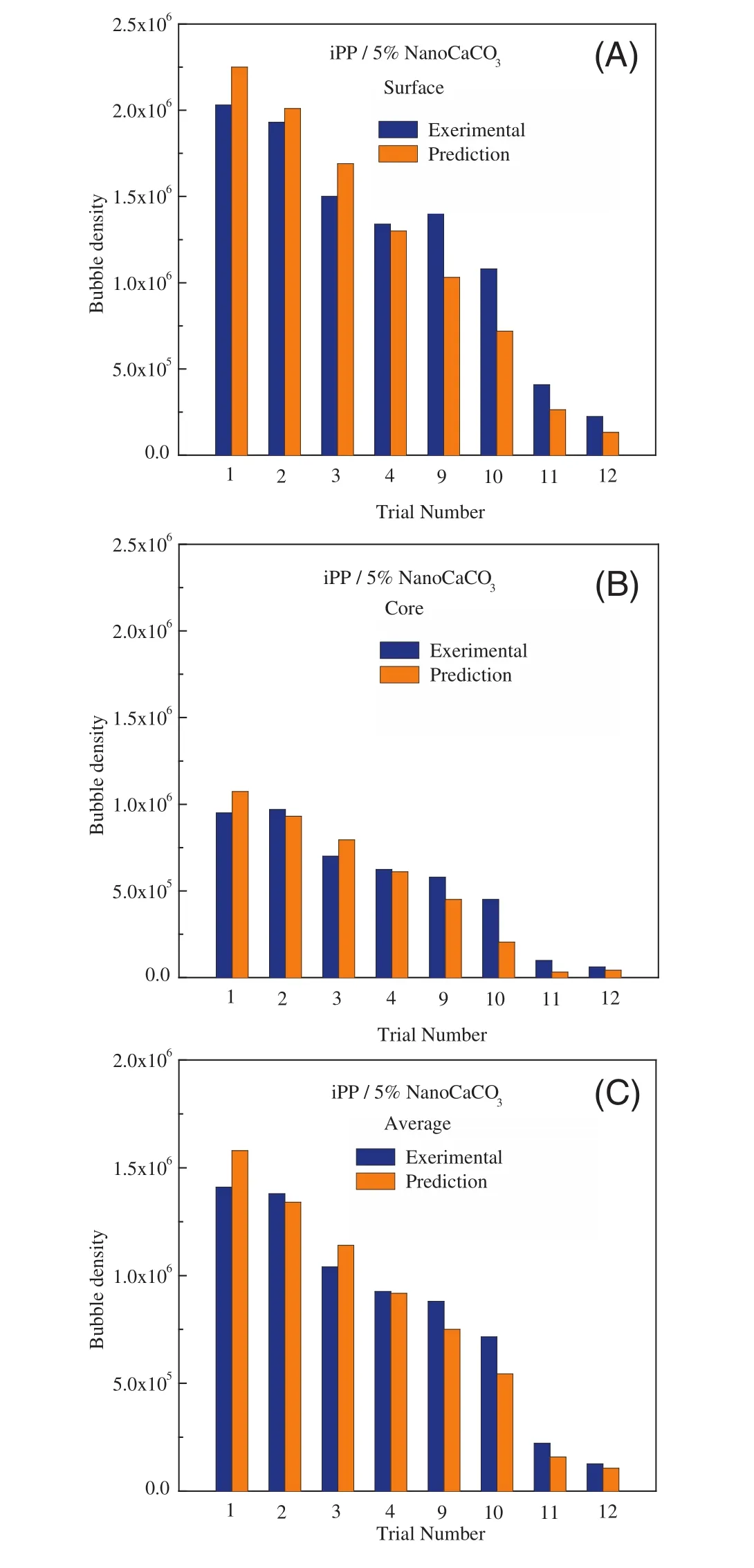
Fig.11.Comparison of bubble density between the experimental and simulated results for foamed iPP/5%nano-CaCO3,(A)surface layer;(B)core layer;(C)average.
[1]N.P.Suh,Innovation in polymer processing,Hanser/Gardner Publications,New York,1996.
[2]D.I.Collais,D.G.Baird,Tensile toughness of microcellular foams of polystyrene,styrene-acrylonitrile copolymer,and polycarbonate,and the effect of dissolved gas on the tensile toughness of the same polymer matrices and microcellular foams,Polym.Eng.Sci.35(1995)1167-1177.
[3]A.Zhang,Q.Zhang,H.Bai,L.Li,J.Li,Polymeric nanoporous materials fabricated with supercritical CO2and CO2-expanded liquids,Chem.Soc.Rev.43(2014)6938-6953.
[4]M.Sauceau,J.Fages,A.Common,C.Nikitine,E.Rodier,New challenges in polymer foaming:A review of extrusion processes assisted by supercritical carbon dioxide,Prog.Polym.Sci.36(2011)749-766.
[5]M.Yuan,L.S.Turng,Microstructure and mechanical properties of microcellular injection molded polyamide-6 nanocomposites,Polymer 46(2005)7273-7292.
[6]J.C.Feng,M.C.Chen,Z.T.Huang,Assessment of efficacy of trivalent lanthanum complex as surface modifier of calcium carbonate,J.Appl.Polym.Sci.82(2001)1339-1345.
[7]J.Zhang,Q.J.Ding,N.L.Zhou,Studies on crystal morphology and crystallization kinetics of polypropylene filled with CaCO3of different size and size distribution,J.Appl.Polym.Sci.101(2006)2437-2444.
[8]T.Labour,C.Gauthier,R.Séguéla,Influence of the β crystalline phase on the mechanical properties of unfilled and CaCO3- filled polypropylene.I.Structural and mechanical characterisation,Polymer 42(2001)7127-7135.
[9]C.M.Chan,J.Wu,J.X.Li,Polypropylene/calcium carbonate nanocomposites,Polymer 43(2002)2981-2992.
[10]J.Ding,W.H.Ma,F.J.Song,Q.Zhong,Effect of nano-calcium carbonate on microcellular foaming of polypropylene,J.Mater.Sci.48(2013)2504-2511.
[11]J.Ding,J.N.Shangguan,W.H.Ma,Q.Zhong,Foaming behavior of microcellular foam polypropylene/modified nano calcium carbonate composites,J.Appl.Polym.Sci.128(2013)3639-3651.
[12]Martini-Vvedensky,J.E.,Suh,N.P.,Waldman F.A.,“Saturation with inert gas,depressurization,and quick-cooling”,U.S.Patent 4,473,665(1984).
[13]J.Xu,D.Pierick,Microcellular foam processing in reciprocating screw injection molding machine,J.Injection Molding Technol.5(2001)152-159.
[14]L.J.Lee,C.Zeng,X.Cao,Polymer nanocomposite foams,Compos.Sci.Technol.65(2005)2344-2363.
[15]S.Hw ang,P.P.Hsu,J.Yeh,C.Hu,K.Chang,Effect of organoclay on the mechanical/thermal properties of microcellular injection molded polystyrene-clay nanocomposites,Int.Commun.Heat Mass Transfer 36(2009)799-805.
[16]G.Q.Zheng,Q.Li,J.B.Chen,C.Y.Shen,W.Yang,M.B.Yang,Gas-assisted injection molded polypropylene/glass fiber composite:Foaming structure and tensile strength,Polym.-Plast.Technol.Eng.48(2009)170-176.
[17]J.F.Gómez-Gómez,D.Arencón,M.A.Sánchez-Soto,A.B.Martínez,Influence of the injection moulding parameters on the microstructure and thermal properties of microcellular polyethylene terephthalate glycol foams,J.Cell.Plast.49(2012)47-63.
[18]H.Y.Mi,X.Jing,J.Peng,L.-S.Turng,X.F.Peng,Influence and prediction of processing parameters on the properties of microcellular injection molded thermoplastic polyurethane based on an orthogonal array test,J.Cell.Plast.49(2013)439-458.
[19]M.F.Kemmere,T.Meyer,Supercritical carbon dioxide:In polymer reaction engineering,WIELY-VCH,Weinheim,Germany,2005.
[20]K.T.Okamoto,Microcellular processing,Hanser,Munich,2003.
[21]D.Li,T.Liu,L.Zhao,Controlling sandwich-structure of PET microcellular foams using coupling of CO2diffusion and induced crystallization,AICHE J.58(2012)2512-2523.
[22]W.Zhai,H.Wang,J.Yu,Foaming behavior of isotactic polypropylene in supercritical CO2influenced by phase morphology via chain grafting,Polymer 49(2008)3146-3156.
[23]G.Q.Zheng,W.Yang,M.B.Yang,J.B.Chen,Gas-assisted injection molded polypropylene:The skin-core structure,Polym.Eng.Sci.48(2008)976-986.
[24]K.F.Zhang,Z.Lu,Analysis of morphology and performance of PP microstructures manufactured by micro injection mold ing,Microsyst.Technol.14(2008)209-214.
[25]J.S.Kim,G.Guo,K.H.Wang,C.B.Park,F.W.Maine,processing/structure/property relationships for artificial wood made from stretched PP/wood- fiber composites,SPE-ANTEC Paper,Chicago,USA,16-19 May 2004.Paper no.809,2004.
[26]A.K.Chaudhary,K.Jayaraman,Extrusion of linear polypropylene-clay nanocomposite foams,Polym.Eng.Sci.51(2011)1749-1756.
[27]K.Taki,T.Yanagimoto,E.Funami,Visual observation of CO2foaming of polypropylene-clay nanocomposites,Polym.Eng.Sci.44(2004)1004-1011.
[28]C.Wang,S.N.Leung,M.Bussmann,W.T.Zhai,C.B.Park,Numerical investigation of nucleating-agent-enhanced heterogeneous nucleation,Ind.Eng.Chem.Res.49(2010)12783-12792.
[29]J.S.Colton,N.P.Suh,Nucleation of microcellular foam:Theory and practice,Polym.Eng.Sci.27(1987)500-503.
[30]S.N.Leung,A.Wong,Q.Guo,Change in the critical nucleation radius and its impact on cell stability during polymeric foaming processes,Chem.Eng.Sci.64(2009)4899-4907.
[31]C.D.Han,C.-Y.Ma,Rheological properties of mixtures of molten polymer and fluorocarbon blowing agent.I.Mixtures of low-density polyethylene and fluorocarbon blowing agent,J.Appl.Polym.Sci.28(1983)831-850.
[32]J.H.Han,C.D.Han,A study of bubble nucleation in a mixture of molten polymer and volatile liquid in a shear flow field,Polym.Eng.Sci.28(1988)1616-1627.
[33]A.C.Papanastasiou,L.E.Scriven,C.W.Macosko,Bubble grow th and collapse in viscoelastic liquids analyzed,J.Non-Newtonian Fluid Mech.16(1984)53-75.
[34]M.Amon,C.D.Denson,A study of the dynamics of foam grow th:Analysis of the grow th of closely sp aced spherical bubbles,Polym.Eng.Sci.24(1984)1026-1034.
[35]K.Taki,Experimental and numerical studies on the effects of pressure release rate on number density of bubbles and bubble grow th in a polymeric foaming process,Chem.Eng.Sci.63(2008)3643-3653.
[36]A.Arefmanesh,S.G.Advani,Diffusion-induced growth of a gas bubble in a viscoelastic fluid,Rheol.Acta 30(1991)274-283.
[37]Y.Li,Z.Yao,Z.H.Chen,K.Cao,S.L.Qiu,F.J.Zhu,C.C.Zeng,Z.M.Huang,Numerical simulation of polypropylene foaming process assisted by carbon dioxide:Bubble growth dynamics and stability,Chem.Eng.Sci.66(2011)3656-3665.
[38]T.Y.Shiu,Y.J.Chang,C.T.Huang,Dynamic behavior and experimental validation of cell nucleation and growing mechanism in microcellular injection molding process,SPE-ANTEC papers,Orlando,2012.
[39]T.C.Chen,C.T.Huang,Y.C.Chiu,W.D.Wang,C.L.Hsu,C.Y.Lin,L.W.Kao,Material saving and product quality improvement with the visualization of hot runner design in injection molding,Int.J.Precis.Eng.Manuf.14(2013)1109-1112.
[40]X.Sun,L.-S.Turng,E.Dougherty,Artificial neural network-based supercritical fluid dosage control for microcellular injection molding,Adv.Polym.Technol.31(2012)7-19.
[41]J.Chen,T.Liu,W.K.Yuan,Solubility and diffusivity of CO2in polypropylene/microcalcium carbonate composites,J.Supercrit.Fluids 77(2013)33-43.
[42]K.Taki,T.Murakami,M.Ohshima,Surface tension of polypropylene and polystyrene in super critical carbon dioxide,A.W.P.P.2002,Singapore,2002.
杂志排行
Chinese Journal of Chemical Engineering的其它文章
- Economic analysis in product design—A case study of a TCM dietary supplement
- Effect of ionic liquids on stability of O/W miniemulsion for application of low emission coating products☆
- Characterization and adsorption behaviors of a novel synthesized mesoporous silica coated carbon composite☆
- Salt-free reactive dyeing of betaine-modified cationic cotton fabrics with enhanced dye fixation☆
- A computational analysis of the impact of mass transport and shear on three-dimensional stem cell cultures in perfused micro-bioreactors
- Production and characterization of exopolysaccharides in mycelial culture of Cordyceps sinensis fungus Cs-HK1 with different carbon sources☆
