Evaluation of substrates for zinc negative electrode in acid PbO2-Zn single flow batteries☆
2016-05-29JunliPanYuehuaWenJieChengJunqingPanShouliBaiYushengYang
Junli Pan ,Yuehua Wen *,Jie Cheng Junqing Pan *,Shouli BaiYusheng Yang
1 State Key Laboratory of Chemical Resource Engineering,Beijing University of Chemical Technology,Beijing 100029,China
2 Research Institute of Chemical Defence,Beijing 100191,China
1.Introduction
Redox flow batteries are a class ofstationary energy storage systems.Different from common secondary batteries employing solid active materials,the active materials of Redox flow batteries are soluble,stored in external reservoir vessel.In normal operation,charged and discharged reactants are circulated through the electrode compartment by pumps.Accordingly,a long cycle life is expected for this rechargeable cell[1].A novelsingle flow battery involving the deposition ofa metallic species has been proposed and developed[2,3],breaking the limit on conventional dual flow batteries with a membrane,which causes spontaneous discharge of different reactive species at anode and cathode.Several systems have been examined including earlier zinc-bromine[4]and zinc-chlorine[5-7],recent soluble lead acid[2,8],zinc-nickel single flow batteries[3],and zinc ion battery[9-12].The flow battery is characterized by charged(ordischarged)products ofatleastone couple deposited on the inert electrode in charge-discharge process.In essence,electrodes themselves serve as an electrical interface and a place for electrode reactions.The nature and form of electrode materials and surfaces play a key role in the charge and discharge efficiencies and cycling stability for Redox flow batteries[6].The effects of substrate electrodeson the formofmetallic deposits and self-discharge rates are ofcritical importance in the design of such systems.
High specific energy,high negative equilibrium potential,good reversibility,low cost,and environmentalfriendliness are some ofthe outstanding merits of zinc electrodes.Zinc has a wide variety of applications as a negative electrode material in batteries such as zinc-silver,zinc-air,and zinc-nickel batteries[13].However,the working voltage ofthese alkaline zinc-based batteries is less than 2 V.As a well-developed positive electrode,PbO2solid electrode with a high equilibrium potential has been widely studied[14,15]and used in acid lead batteries.The application and developmentofacid lead battery are limited owing to its poorcycling life and low energy density.Thereby,we have developed acidic PbO2-Zn single flow battery with a highest open-circuit voltage of 2.4 V[16,17],with a sulfuric acid solution containing zinc ions as the electrolyte.With concentrated SO42-ions,a large part of hydrogen ions from the ionization of H2SO4are converted to HSO4-ions,so that the concentration of free hydrogen ions is minimized.During charging,the metal ions at the negative electrode move from the solution and deposit onto the inert carbon substrate(Zn2++2e-→Zn),whereas at the positive electrode,oxidation of PbSO4to PbO2occurs at a lead-alloy grid electrode(PbSO4++2H2O-2e-→PbO2+H++.During discharging,reverse process occurs,forming highly soluble products in the acid electrolyte at the zinc electrode.In an acid aqueous solution of zinc sulfate,it is easy to form fine grained,smooth and compact deposits.Thus,the sulfuric acid solution containing zinc ions has been used as electrolyte for electro deposition of zinc[18-20].
In this paper,we focus on the negative electrode side of acid PbO2-Zn single flow battery and investigate Zn deposition/dissolution process on a number of carbon and lead electrodes.Cyclic voltammetry,potentiostatic current transients and cathode potentiodynamic polarization measurements(lg i-E),as well as galvanostatic charge/discharge cycles are employed in order to evaluate the effectiveness,robustness and potential use of several carbon and lead composite materials in the Redox flow cell.
2.Experimental
The lead alloy samplesused in this study were essentially lead materials doped with a minimum amount of other metals with high hydrogen overpotential.The composition of lead grid alloys is listed in Table 1.The main componentadded is Sn,followed by Ca and Zn.5%bismuth and 95%lead were melted and stirred at high temperature,then cooled to room temperature and cut into the electrodes with the volume of 2×2×0.3 cm3.The lead alloy electrodes were obtained.The graphite composite samples were graphite materials doped with a certain amount of polymer resin,which was obtained from Shanghai Heixia carbon product Co.
For the electrochemical study,a standard 3-electrode configuration was employed,with a graphite and its composite or lead and its alloy(area:1×1 cm2)asworking electrodes,a large lead plate as the counter electrode,and Hg/Hg2SO4as the reference electrode.All potentials are reported with respect to this reference.
In the cyclic voltammograms,potentiostatic polarization(E-lg i)was carried out at room temperature using a Solartron1280z electrochemical station.The scan rate for all the cyclic voltammograms was 20 mV·s-1between potential limits of-1 and-1.7 V.For the cyclic voltammograms,the 1 mol·L-1H2SO4solution containing 1.25 mol·L-1Zn(II)was employed as the electrolyte.The galvanostatic charge/discharge cycles were conducted in a three-electrode cell at room temperature,and each charge-discharge cycle was discharged to 1 V vs.Hg/Hg2SO4.A graphite and its composite or lead and its alloys(area:2×2 cm2)were used as the working electrodes.Two sheets of PbO2/PbSO4solid electrode(area:4.5×5 cm2)were counter electrodes.An electrode of Hg/Hg2SO4acted as the reference electrode.A Solartron1280z Electrochemical Interface controlled by Corrware software was employed.The morphology of electrodeposits on graphite composite and lead surfaces after cycling experiments was examined using SEM(Cambridge Instruments APollo300).In the experiment,the solution was stirred using a magnetic stirrer.
3.Results and Discussion
3.1.Electrochemical characterization
Fig.1 shows the cyclic voltammograms in 1 mol·L-1H2SO4containing 1.25 mol·L-1Zn2+on different substrate electrodes.Some data from Fig.1 are summarized in Table 2.With lead as the substrate electrode,the zinc deposition process was initiated at point A(-1.56 V vs.Hg/Hg2SO4),scanned in the negative direction and reversed at-1.7 V in the positive direction.The current increased sharply to point C,where it was reversed.The current decreased and reached zero at point B,and then became anodic corresponding to the dissolution of deposited zinc.The potential difference between points A and B is a measure of nucleation overpotential(NOP)[21].NOP is regarded as an indicator of the extent of polarization of a cathode,and high NOP values indicate strong polarization of cathode.Point A is referred to as the nucleation potential(Enu),corresponding to the reduction of Zn2+ions.Point B is referred to as the cross-over potential where the current reaches zero,also called as the formal potential.The values of NOP(as shown in Table 2)for other substrates can be determined from the cyclic voltammograms in the same way.It is found that the onset for the zinc deposition process is the lowest on lead substrate and the next is on the graphite composite with relatively large value of NOP,which is up to 68-80 mV.On the contrary,the deposition potential shifts to more positive values for the graphite electrode and two lead alloys.NOP values are also significantly lowered,particularly for the graphite electrode,with the NOP value of 20 mV.This indicates that the cathodic polarization for the zinc deposition on the lead and graphite composite substrates is larger than the other three substrate electrodes.The nextis the graphite composite electrode rather than the two lead alloys.The rate of growth of zinc layer at the lead surface is the slowest among the five electrode materials.This indicates that the zinc deposition-dissolution process from acid sulfate solution is related to the texture and electrochemical features of substrate electrodes.The difference is little in the dissolution potential(Edis)for the zinc dissolution,but the substrates exert great in fluences on the anodic dissolution peak current.Anodic peak current density of zinc on the graphite electrode is much higher than that on the other substrates,corresponding to the smallest value of NOP.The next is the graphite composite electrode.The anodic peak current densities of zinc on the lead and lead alloy substrates are close and the lowest.
Suppressing H2formation is critical for the zinc deposition process,particularly in the acidic medium.The rate of hydrogen evolution reaction(HER)depends on the overpotential of hydrogen on the substrate electrode for zinc deposition.Fig.2 shows cathodic polarization curves at 10 mV·s-1from the rest potential of the zinc electrode in 1 mol·L-1H2SO4solution with various substrate electrodes.The hydrogen overpotentialis the lowestfor the graphite electrode.The currentof hydrogen evolution increases sharply with scanning in the negative direction.However,the hydrogen overpotential increases to a great extent on the graphite composite electrode.It indicates that the addition of some resin polymer can slow the rate of HER remarkably on graphite.The onsetofhydrogen evolution forthe lead and lead grid alloy is earlier compared to the graphite composite electrode.However,with the potential scanning to a more negative value,the current of hydrogen evolution on the lead and lead grid alloy electrodes increases more slowly than that on the graphite composite electrode.Comparatively,the rate of HER on the lead grid alloy is a bit faster than that on lead.The rate of HER decreases on the lead-Bi alloy compared to the lead and lead grid alloy.Consequently,for raising the hydrogen over-potential for zinc deposition,the graphite composite is the most effective,followed by lead and lead grid alloy.The side reaction of hydrogen evolution on the graphite and Pb-Bi alloy is relatively serious.Moreover,it may suggest that the rate of HER could be slowed down considerably on lead and lead grid alloy for the zinc electro-deposition at a high polarization potential or a high current density.
lg i-E curves for 1.25 mol·L-1Zn(II)ions in 1 mol·L-1H2SO4at different substrate electrodes are presented in Fig.3.The anodic and cathode Tafel slopes,baand bc,exchange current density,I0,and formal potential,E0,are calculated from lg i vs.E curves,as shown in Table 3.I0is regarded as an indicator of the rate of zinc deposition and dissolution,and high I0values indicate high rate of zinc electrode reaction.The I0value of zinc deposition and dissolution on the graphite composite electrode is lower by one order ofmagnitude compared to other substrate electrodes.Among the lead and its alloys,the I0value on the Pb-Bi alloy is the highest,followed by lead grid alloy and lead.As thehydrogen overpotential increases,the formal potential(E0)for the zinc deposition and dissolution shifts to a more negative value.This corresponds to the features of hydrogen evolution on these substrate electrodes.That is,the lower the hydrogen overpotential,the higher the I0value of zinc deposition and dissolution.Moreover,the cathodic Tafel slope is close to the anodic slope for the graphite composite and lead electrodes,indicative of cathode and anode mixed control.For lead grid and Pb-Bi alloys,the cathodic Tafel slope is greater than the anodic slope.This suggests that the reaction is under cathode control.

Table 1 Composition of lead alloy

Fig.1.Cyclic voltammograms of different substrate electrodes in 1.25 mol· L-1 Zn2+in 1 mol·L-1 H2SO4 at 25 °C and a scan rate of 20 mV·s-1(substrate electrode:1—graphite;2—graphite composite;3—Pb;4—Pb-Bi alloy;5—lead grid alloy).

Table 2 Effect of substrate electrodes on nucleation potential(E nu),nucleation overpotential(NOP)and dissolution peak potential(E dis),anodic peak current density(I ac)during zinc electro-deposition dissolution from acid sulfate solution
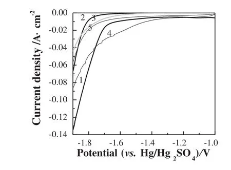
Fig.2.Effect of substrate on hydrogen evolution reaction for zinc deposition in 1 mol·L-1 H2SO4 solution(substrates:1—graphite;2—graphite composite;3—Pb;4—Pb-Bi alloy;5—lead grid alloy;scan rate:10 mV·s-1).

Fig.3.lg i-E curves for 1.25 mol⋅L-1 Zn(II)ions in 1 mol·L-1 H2SO4 solution at different substrate electrodes(substrates:1—lead grid alloy;2—Pb-Bi alloy;3—lead;4—graphite composite;5—graphite).
3.2.Charging and discharging performance
To illustrate the effectiveness of these carbon and metal materials as the substrate of negative zinc electrode in acidic PbO2-Zn single flow batteries,the stability of substrate electrodes to repeated zinc deposition and dissolution was examined in a three electrode system under a variety of conditions.Fig.4 shows the coulombic efficiency as a function of cycling number in charging and discharging at various current densities in the range of 10-150 mA·cm-2for 300 s with differentsubstrate electrodes in 1 mol·L-1H2SO4solution containing 1.25 mol·L-1Zn2+ions.The coulombic efficiency(Qeff)and energy efficiency(Eeff)of zinc electrode are important for evaluation of the performance of zinc half cell.The coulombic efficiency refers to the ratio of the discharge capacity to the charge capacity of the battery.The voltage efficiency is the ratio of the average discharge voltage to the average charge voltage of the battery.The energy efficiency is the coulombic efficiency multiplied by voltage efficiency.In general,Qeffis enhanced with increasing current density.When the current density is as low as 10 mA·cm-2,Qeffis less than 80%apart from the graphite composite and lead electrodes.For the graphite composite electrode,at 30 mA·cm-2,Qeffis increased to around 90%.This increase is not significant for current densities greater than 50 mA·cm-2.In contrast,this change forthe graphite electrode is 88%at150 mA·cm-2and 66%-80%at30 mA·cm-2.For the two lead alloys,Qeffis over 90%when the current density is raised to 150 mA·cm-2.For the lead electrode with relatively high hydrogen overpotential,Qeffis not sensitive to current density.As current density increases,Qeffincreases slightly.Qeffis up to 82%at 10 mA·cm-2while it is only about87%at150 mA·cm-2.This corresponds to a competition between the zinc deposition and the corrosion of zinc in acid solution.At high current densities,this dependence of Qeffis due to decreasing competition from the zinc corrosion.The lower the hydrogen overpotential,the more serious the corrosion of zinc.Thus,though the I0value on the graphite composite is one order of magnitude lower than that on the other substrate electrodes,the corrosion is not serious even at the lowestcurrentdensity employed for the graphite composite electrode with the high hydrogen overpotential.
For the deposition of electrodes,the charge period is also an important factor.Hence,the effect of charging period on the performance of zinc deposition is studied.The current density is fixed at 20 mA·cm-2and the charge time is from 1200 s to 7200 s in 1 mol·L-1H2SO4solution containing 1.25 mol·L-1Zn2+ions.The dependence of Qeffand Eefffor the graphite composite electrode is shown in Fig.5.The deposition time below 5400 s gives high Qeff,∼90%.As the deposition time goes to 7200 s,Qeffdecreases sharply at the fourth cycle.And then,as cycling number increases,Qeffreduces continuously from 88%to less than 80%.The decreasing trend of Eeffwith current density is clear when the shortest deposition time of 1200 s gives the highest Eeff,~83%,and the longest deposition time of 7200 s reduces Eeffto~70%.For the deposition time of 7200 s,the variation in Eeffwith cycling numberis great,with the efficiency decreasing from 76%to 66%for 10 cycles.The deposition time of 7200 s simply exacerbates the stability of zinc deposition and dissolution in the acid medium.Therefore,in 1 mol·L-1H2SO4solution,the time of zinc deposition should be less than 5400 s.

Table 3 Kinetic data of zinc deposition-dissolution at different substrate electrodes in 1 mol·L-1 H2SO4 solution containing 1.25 mol·L-1 Zn2+ions

Fig.4.Effect of current density on the coulombic efficiency for various substrate electrodes in 1.25 mol·L-1 Zn2+and 1 mol·L-1 H2SO4 at 25 °C(charge time:300 s;substrates:(a)graphite;(b)graphite composite;(c)Pb;(d)Pb-Bi alloy;(e)lead grid alloy).

Fig.5.Effect of charging time on coulombic efficiency(a)and energy efficiency(b)for the graphite composite in 1.25 mol·L-1 Zn2+and 1 mol·L-1 H2SO4 solution at 25 °C and current density of 20 mA·cm-2.

Fig.6.Comparison of Q eff and E eff for different substrate electrodes in 1 mol·L-1 H2SO4 and 1.25 mol·L-1 Zn2+solution at 25 °C.Charge time=3600 s at 20 mA·cm-2.Discharge at 20 mA·cm-2.
Fig.6 shows the charge and discharge performance of different substrate electrodes,at 20 mA·cm-2for 3600 s in 1 mol·L-1H2SO4solution containing 1.25 mol·L-1Zn2+ions.The graphite composite electrode presents the highest coulombic and energy ef ficiencies,~90%and ~80%,respectively.This composite material also exhibits the best stability to cycling,with little deterioration in Qeffand Eeff.This is different from the lead substrate electrode,which degrades substantially with cycling.For the Pb-Bi and lead grid alloys,the coulombic and energy average efficiencies are only 80%and 60%,respectively.
The differences in electrochemical performance of substrate electrodes in acidic zinc sulfate solutions are associated with the morphology of deposited Zn.Fig.7 shows the SEM micrographs of the zinc deposits on the electrode surfaces with different charging periods.The conclusion is drawn from the investigations on hydrogen evolution reaction HER for zinc deposition,the charge and discharge performance of zinc electrode,the cyclic voltammograms,the kinetic analysis by Tafel slopes,and the SEM micrographs.For the graphite composite electrode,depositsare more compactwith longerdeposition time,which is associated with high over-H2-potentialand differenttexture and electrochemical features of substrate electrodes.Thus,hydrogen evolution on the composite graphite is effectively suppressed due to the addition of a polymer resin[22].Zinc corrosion is prevented to a certain extent.On the contrary,the zinc deposit is porous and loose with long deposition time for the lead electrode.
4.Conclusions
The suitability of carbon and metallic lead materials as substrate electrodes of zinc negative electrode in PbO2-Zn single flow battery was investigated.It showed that the nucleation mechanism of zinc deposition on carbon materials was completely from that on metallic lead materials.No maximum current appeared on the potentiostatic current transients for the zinc deposition on the lead and its alloys.Increasing the overpotential,the progressive nucleation turned to be a 3D-instantaneous nucleation process for the graphite composite.Hydrogen evolution on the graphite composite was effectively suppressed due to the doping ofa polymer resin.The rate of hydrogen evolution reaction on the lead was relatively weak,while on the lead alloys,it became more serious.Although the exchange current density on the graphite composite was lower by one order of magnitude compared to other substrate electrodes,corrosion was notserious even atthe lowest current density.Furthermore,the zinc deposits tended to be more compact with the deposition time prolonged.Zinc galvanostatic charge-discharge cycling on carbon and lead substrates revealed that the graphite composite electrode had no loss in efficiency with cycling,and a drastic reduction was observed for the lead electrode,accompanied by the physical deterioration in the electrode surface.

Fig.7.SEM micrographs of Zn deposits in 1.25 mol·L-1 Zn2+and 1 mol·L-1 H2SO4 solution at 25 °C for graphite composite after deposition for 300 s(a)and 3600 s(b),lead after deposition for 300 s(c)and 3600 s(d).
References
[1]C.Ponce de León,A.Frías-Ferrer,J.González-García,D.A.Szánto,F.C.Walsh,Redox lf ow cells for energy conversion,J.Power Sources 160(2006)716-732.
[2]A.Hazza,D.Pletcher,R.Wills,A novel flow battery:A lead acid battery based on an electrolyte with soluble lead(ii),Phys.Chem.Chem.Phys.6(2004)1773-1778.
[3]J.Cheng,L.Zhang,Y.S.Yang,Y.H.Wen,G.P.Cao,X.D.Wang,Preliminary study of single flow zinc-nickel battery,Electrochem.Commun.9(2007)2639-2642.
[4]T.I.Evans,R.E.White,A review of mathematical modeling of the zinc/bromine flow cell and battery,J.Electrochem.Soc.134(1987)2725-2733.
[5]D.Loftus,J.Roberts,R.Weaver,S.Leach,L.Nanis,Diffusivity in zinc chloride-potassium chloride electrolyte,J.Electrochem.Soc.130(1983)332-334.
[6]G.Nikiforidis,L.Berlouis,D.Hall,D.Hodgson,Evaluation of carbon composite materials for the negative electrode in the zinc-cerium redox flow cell,J.Power Sources 206(2012)497-503.
[7]F.Yu,M.Y.Zhu,X.G.Wang,G.Wang,P.R.Qi,D.Chen,B.Dai,Clean energy and energy storage research—The 2nd international conference on clean energy sciences,Energy Storage Sci.Technol.3(2014)457-470.
[8]A.Hazza,D.Pletcher,R.Wills,A novel flow battery—A lead acid battery based on an electrolyte with soluble lead(II),J.Power Sources 149(2005)103-111.
[9]C.Xu,B.Li,H.Du,F.Kang,Energetic zinc ion chemistry:The rechargeable zinc ion battery,Angew.Chem.51(2012)933-935.
[10]D.Xu,B.Li,C.Wei,Y.B.He,H.Du,X.Chu,X.Qin,Q.H.Yang,F.Kang,Preparation and characterization of MnO2/acid-treated CNT Nanocomposites for energy storage with zinc ions,Electrochim.Acta 133(2014)254-261.
[11]C.Wei,C.Xu,B.Li,H.Du,F.Kang,Preparation and characterization of manganese dioxides with nano-sized tunnel structures for zinc ion storage,J.Phys.Chem.Solids 73(2012)1487-1491.
[12]M.H.Alfaruqi,J.Gim,S.Kim,J.Song,J.Jo,S.Kim,V.Mathew,J.Kim,Enhanced reversible divalentzinc storage in a structurally stable α-MnO2nanorod electrode,J.Power Sources 288(2015)320-327.
[13]J.X.Yu,H.X.Yang,X.P.Ai,X.M.Zhu,A study of calcium zincate as negative electrode materials for secondary batteries,J.Power Sources 103(2001)93-97.
[14]S.Tong,T.Zhang,C.A.Ma,Oxygen evolution behavior of PTFE-F-PbO2electrode in H2SO4 solution,Chin.J.Chem.Eng.16(2008)885-889.
[15]X.Hong,R.Zhang,S.Tong,C.A.Ma,Preparation of TiPTFE-F-PbO2electrode with a long life from the sulfamic acid bath and its application in organic degradation,Chin.J.Chem.Eng.19(2011)1033-1038.
[16]J.Pan,Y.Wen,J.Cheng,J.Pan,Z.Bai,Y.Yang,Zinc deposition and dissolution in sulfuric acid onto a graphite-resin composite electrode as the negative electrode reactions in acidic zinc-based redox flow batteries,J.Appl.Electrochem.43(2013)541-551.
[17]P.K.Leung,Q.Xu,T.S.Zhao,High-potential zinc-lead dioxide rechargeable cells,Electrochim.Acta 79(2012)117-125.
[18]B.C.Tripathy,S.C.Das,P.Singh,G.T.Hefter,V.N.Misra,Zinc electrowinning from acidic sulphate solutions part IV:Effects of per fluorocarboxylic acids,J.Electroanal.Chem.565(2004)49-56.
[19]C.Cachet,R.Wiart,In fluence of a per fluorinated surfactant on the mechanism of zinc deposition in acidic electrolytes,Electrochim.Acta 44(1999)4743-4751.
[20]S.Han,B.Qiu,Z.Wei,Y.Xia,Z.Liu,Surface structuralconversion and electrochemical enhancement by heat treatment of chemical pre-delithiation processed lithium-rich layered cathode material,J.Power Sources 268(2014)683-691.
[21]Q.B.Zhang,Y.Hua,Effect of Mn2+ions on the electrodeposition of zinc from acidic sulphate solutions,Hydrometallurgy 99(2009)249-254.
[22]A.E.Alvarez,D.R.Salinas,Nucleation and growth of Zn on HOPG in the presence of gelatine as additive,J.Electroanal.Chem.566(2004)393-400.
杂志排行
Chinese Journal of Chemical Engineering的其它文章
- Synthesis of water-soluble acryl terpolymers and their anticorrosion properties on mild steel in 1 mol·L-1 HCl
- Prediction of pyrolysis kinetic parameters from biomass constituents based on simplex-lattice mixture design☆
- Production of carbonaceous material from avocado peel for its application as alternative adsorbent for dyes removal
- Production of succinic acid in basket and mobile bed bioreactors—Comparative analysis of substrate mass transfer aspects☆
- Enhanced production of glycyrrhetic acid 3-O-mono-β-D-glucuronide by fed-batch fermentation using pH and dissolved oxygen as feedback parameters☆
- Continuous production of biodiesel from cottonseed oil and methanol using a column reactor packed with calcined sodium silicate base catalyst☆