Robot impedance control and passivity analysis with inner torque and velocity feedback loops
2016-05-14MicheleFOCCHIGustavoMEDRANOCERDAThiagoBOAVENTURAMarcoFRIGERIOClaudioSEMINIJonasBUCHLIDarwinCALDWELL
Michele FOCCHI,Gustavo A.MEDRANO-CERDA,Thiago BOAVENTURA,Marco FRIGERIO ,Claudio SEM INI,Jonas BUCHLI,Darw in G.CALDWELL
1.Departm ent of Advanced Robotics,Istituto Italiano di Tecnologia(IIT),via Morego,30,16163 Genova,Italy;
2.Agile&Dexterous Robotics Lab,ETH Z¨urich,Tannenstrasse 3,8092 Z¨urich,Switzerland
1 Introduction
Until recently, the majority of legged robots employed high-gain (stiff) position feedback control [1]. However,this approach is unsuitable when a robot is in contact with unstructured real-world environment, as the controller would try to satisfy the position goal at all costs [2]. Instead, for such scenarios, a force/torque control in joint or end-effector space is desirable.
For a legged robot,force control can be useful in both the swing and stance phase.During stance,it allow s to control the ground impact forces,with the purpose to improve balance capabilities.During the swing phase,it p lays a crucial role in providing to the robot’s leg the compliance necessary to negotiate unperceived obstacles,while still ensuring a good position tracking by us-ing rigid body inverse dynamics.Interaction forces can be regulated in two ways:passively and actively.Passive methods are those in which physical com pliant elements are included between the robot and the environment to limit the interaction forces(e.g.,a passive spring in series elastic actuators[3,4]).On the other handactivecompliance is achieved through the active control of joints(position or torque)using feedback measurements of joint torques[5].This canemulateavirtualcompliance both at the joint as well as at the end-effector/foot level.
A major benefit of active compliance is its ability to change the dynamic characteristics(e.g.,stiffness and dam ping)in real-time.Hence,legged robots can take advantage of active compliance to adapt the leg stiffness to swing and stance phases,or to the surface properties[6].Many methods to actively control compliance at the end-effector have been developed,such as impedance control[7],operational space control[8],hybrid force-control[9],and virtual model control[10].impedance control,in particular,allows the dynamic characteristics at the robot interaction port(e.g.,the end-effector)to be specified by regulating the dynamic relationship between forces and positions(mechanical impedance).Despite impedance is of primary importance to achieve dynamically stable robot locomotion,only recently an exhaustive research has been carried out,on the M IT Cheetah robot,to find which impedance parameters are suitable for locomotion[11].However,an analysis that investigates if these parameters arerealizableis still missing.
In the past,impedance control algorithm s were limited by the controller bandwidth,which was set by the computational power and actuator dynamics.That was one of the reasons for the introduction of passive elements in series with the actuator[12],which have intrinsically unlimitedbandwidth.However,recent advances in both computer and actuator performance,made active compliance feasible for highly-dynamic applications[13,14].Nevertheless,many aspects,still create stability issues on impedance control.For instance,the range of stable stiffness and dampings that can be virtually created(Z-width[15],whereZstands for impedance[16])can be limited by filtering,sampling frequency,and also by the bandwidth of inner control loops(e.g.,a torque loop).
A common practice in designing nested loop control system s is to maximize the bandwidth of the innermost loop[17].However,maximizing the inner loop controller bandwidth is not always the best strategy.When the outer impedance loop is closed,designing the inner loop to have the highest possible bandwidth reduces the range of impedance parameters for which the whole system is stable,as demonstrated later in this work.Therefore,a trade-off must be found between:having a high bandwidth to ensure good torque and impedance tracking,and keeping the bandwidth low to increase the range of stable impedance values.Other aspects that directly influence the stability region are the sampling frequency and filtering[18].Their effect is to introduce delays into the control loop,and their influence will also be investigated in this work.To ensure closed-loop stability during interactions with the environment or other system s,the controller must be designed to ensure the system behavespassivelyat the interaction port[19,20].From the passivity property,asymptotic stability can always be ensured:both in free motion as well as w hen the robot is in contact with any type of environment(which is usually passive).Physical compliant elements and rigid bodies are passive by nature.However,when the com pliant behavior is emulated by an actuator,the passivity is a function of the controller gains.In this work it will be shown that passivity can also be a restrictive condition to select impedance parameters.
Related worksThe published literature about active compliance is vast.A brief review on the issues that affect the performance of force controlled robots can be found in[21].Stability analysis and performance specifications for compliance control was first introduced by Kazerooni et al.[22]for a manipulator whose model had bounded uncertainty.Lawrence[23]considers the non-ideal,practical effects of computation and communication delays on impedance control and finds some stability boundaries.However,his analysis was in continuous time and it is not necessarily valid for discrete time system s.Indeed sampling is not completely equivalent to time delays because when sampling there are additional zeros that do not appear in continuous time.
Regarding controllers based on passivity,Albu-Schaffer et al.[20]implemented a fullstate controller for joint or Cartesian impedance with passive capabilities.The controller is not passive itself but it is together with the motor dynamics.The torque feedback shapes the rotor inertia of the motors to a desired value.More recently,Buerger and Hogan[24]have revisited the problem of designing controllers for physically interactive robots.For a 1 Do Fsystem,they reformulated the problem as a robust stability problem based on μ-synthesis(structured singular values)and loop shaping meth-ods.The approach provides improvements in robot performance com pared to traditional passive controllers.In[25]stiffness and impedance control concepts were used for robot-aided rehabilitation.New stability conditions w ere proposed using Lyapunov approach and based on the relationship between the dynamics of the robot and its energy.In[26]Yasrebi et al.carried out a time-domain passivity analysis of theZ-width diagram.This led to the design of a new haptic controller which extended the range of stable impedance parameters(Z-width)by means of an acceleration feedback.The analysis was carried out for one joint using passivity theory in the frequency domain.
The main contribution of this work,is a methodology to analyze(based on an accurate model)stability and passivity of a gearbox driven actuator(plus load)system.The analysis takes into account all the non-idealities present inrealimplementation of animpedancecontroller,namely:actuator dynamics,discrete implementation,filtering,nested loops.This allow s to find the impedance“stability regions”which represent the impedance parameters that can berenderedin astableway.Simulations and experimental data show how the above-mentioned non-idealities influence thestability regionsas well as the passivity of the system.The study is carried out for the adduction/adduction(HAA)joint of the HyQ[27]robot(see Fig.1),where impedance control was implemented with an inner torque loop[28].However,the underlying ideas arevalidfor any electric actuator moving a load with a gearbox reduction.In the bigger picture,thestability regionsare the basis to develop a gain scheduler(in the low-level control layer)which is able to adapt the bandwidth of the inner torque loop according to the impedance parameters set by the user.
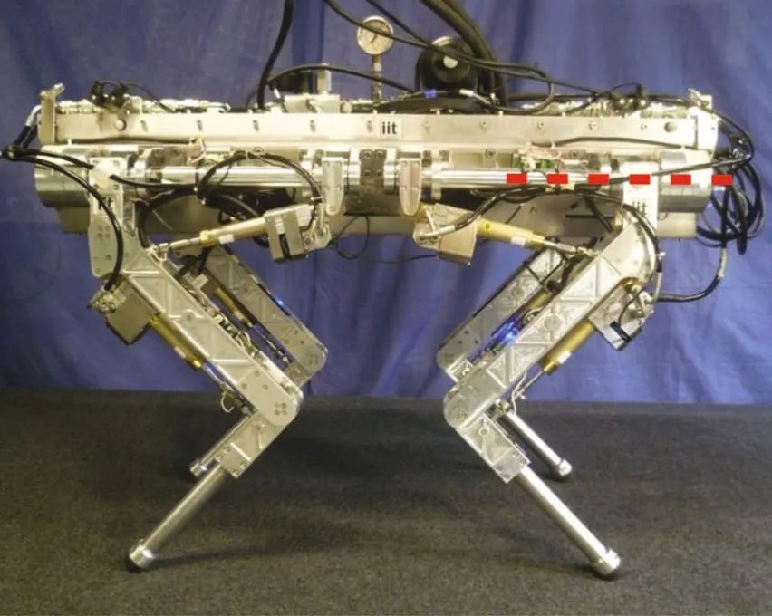
Fig.1 Picture of a lateral view of the HyQ robot,the HAA joint axis is marked in red.
This paper is structured as follows: the mathematical model of the system is introduced in Section 2 followed by a description of the control system implementation in Section 3. The stability issues associated with real implementation of an impedance controller are analysed,both in simulations and experimentally, in Section 4. A brief assessment about passivity for the system is thengiven in Section 5. Finally, Section 6 discusses the results and future works.
2 System description and mathematical model
The studies and experiments presented in this work are all conducted on HyQ [27]. HyQ is a fully torquecontrolled quadruped robot with a mix of hydraulic and electric actuation for each leg: two hydraulic joints on the sagittal plane (hip HFE and knee KFE flexionextension)and one electric joint moving in the traversal plane (hip adduction-abduction HAA, Fig. 2 on the left). This paper focuses on modeling and control of the electric joint, which consists of a DC brush-less motor(Emoteq HT2301) and a harmonic drive gearbox (CSD-25-100). The leg is attached to the gearbox output via an interface consisting of 6 parallel pins (evenly distributed on a circle around the axis of rotation) that enable easy dismounting (see Fig. 3). This interface represents a small intermediate rotational inertia(JL1)placed before the inertia represented by the leg(JL2)in the transmission train.
Normally,this type of assembly is modelled by two second order differential equations coup led via the gearbox transmission flexibility[29].However,after performing several open loop tests using chirp signals,an anti-resonance was detected for the link velocity(see the frequency response of the link velocity to a chirp input voltage in Fig.4).
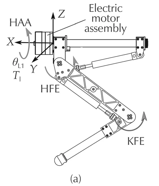
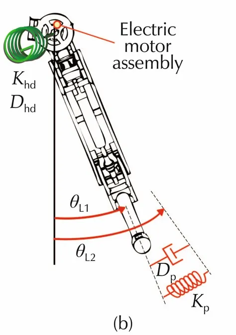
Fig.2 HyQ leg.(a)Lateral and(b)frontal view.The figures show the definition of the joints and their angles,as w ell as the coordinate frame.
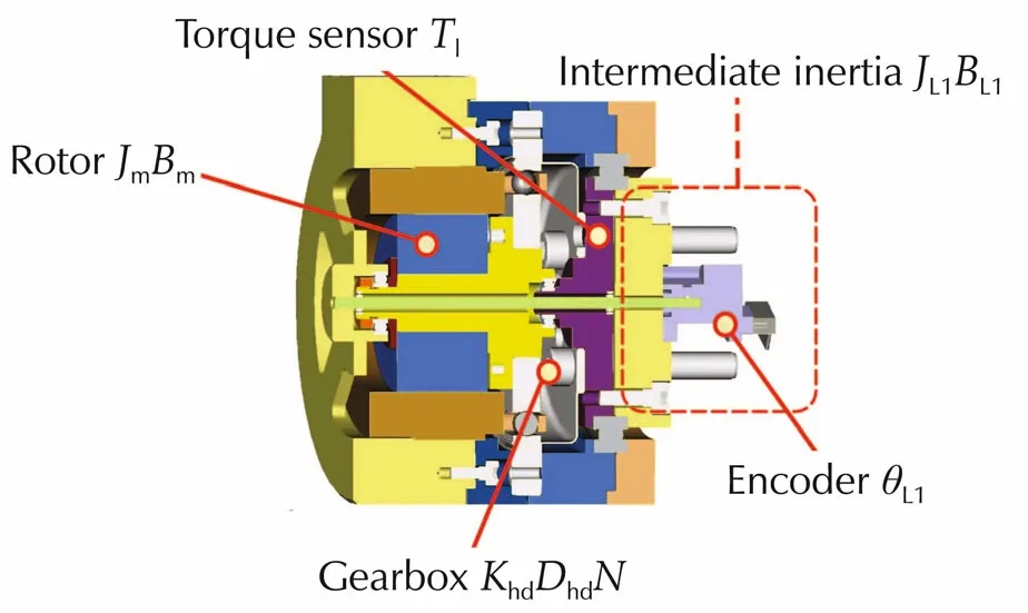
Fig.3 Cross-section of the mechanical assembly of the electric joint.The intermediate inertia J L1 represents the part that interfaces the leg with the gearbox output.
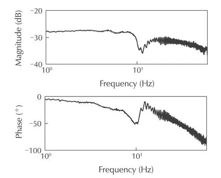
Fig.4 Frequency response of the link velocity˙θL1 to a chirp input voltage at the HAA motor,experimentally obtained with an unconstrained HyQ leg.
Since a model with two inertia and one spring cannot capture this behavior,a m ore com p lex model with three inertia coupled by springs was used,as shown in the schematic in Fig.5 whereKhdandKpare the stiffness related to the gearbox and the leg flexibility,respectively.
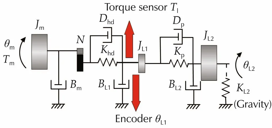
Fig.5 Motor drive system with torsional load,schematic for the 3 mass-2 spring model.
Joint position and torque are measured by an encoder and a torque sensor.Due to the topology depicted in Fig.3 the position encoder measures the angle of the intermediate inertiaJL1while the link velocity is measured by averaging first order differences(4 samples)of the position encoder(averaging filter).In addition a strain gage based torque sensor is mounted at the output of the harmonic drive.No filter is implemented on the torque signal because it would introduce delays in the control action.According to this model,the Lap lace transform s of the differential equations that describe the linearized dynamics of the load and of the electric motor are
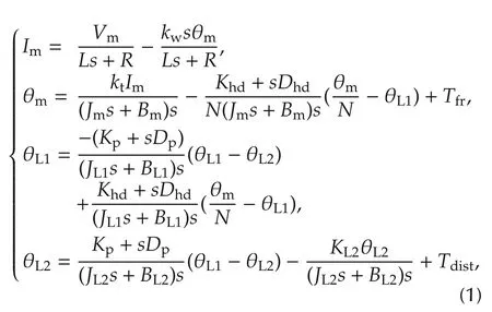
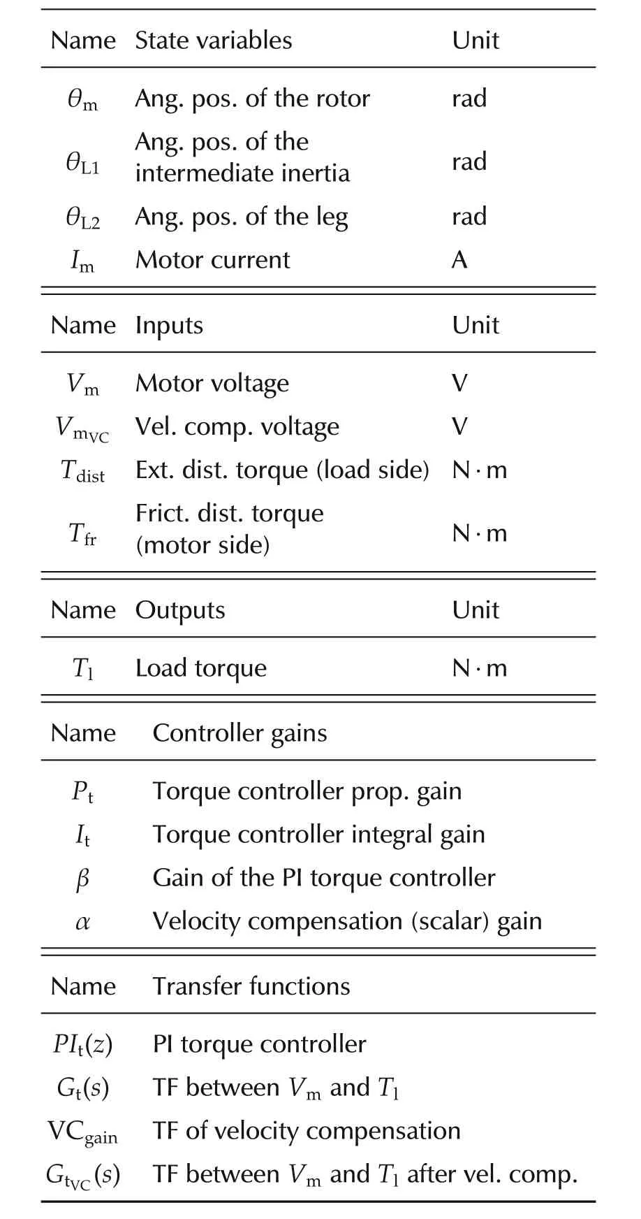
whereIm,θmdenote the motor current and motor position;θL1and θL2are the intermediate inertia and leg positions;Vmis the motor voltage;Tfris the friction torque in the harmonic drive andTdistis an external disturbance torque applied to the leg.All other symbols and parameter values are given in Table 1.A block diagram that illustrates the relationships between the state variables is depicted in Fig.6.Since the rotational inertia of the legJL2varies with the configuration of the joints HFE and KFE,the table includes also upper and lower bounds for the leg inertia.In particular the fact that the leg can retract or extend results in different m ass distributions around the hip abduction-adduction axis.Namely,the inertia is higher when the leg is extended and lower when it is retracted.Gravity has also an effect on the load dynamics,that,w hen linearized,behaves as arotationalspringKL2.The stiffness of this”gravity spring”is also dependent on the leg configuration and is reported in Table 1 for an extended and retracted leg configuration.
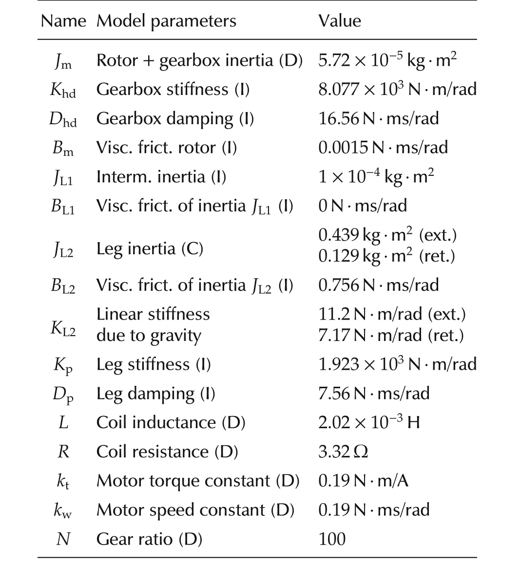
Table 1 Model parameters.
Name State variables Unit θm Ang.pos.of the rotor rad θL1 Ang.pos.of the rad intermediate inertia θL2 Ang.pos.of the leg rad I m Motor current A Name Inputs Unit V m Motor voltage V V m VC Vel.com p.voltage V T d ist Ext.dist.torque(load side)N·m T fr Frict.dist.torque N·m(motor side)Name Outputs Unit T l Load torque N·m Name Controller gains P t Torque controller prop.gain I t Torque controller integral gain βGain of the PI torque controller αVelocity compensation(scalar)gain Name Transfer functions PI t(z)PI torque controller G t(s)TF between V m and T l VCgain TF of velocity compensation G tVC(s)TF between V m and T l after vel.com p.

Fig.6 Block diagram representing equation(1)that describes the linearized dynamics of the electric motor and of the load.V m is the voltage input,T fr the harm onic-drive disturbance torque,T d ist is an external disturbance torque coming from the load side,θm is the motor position,and θL1 and θL2 the positions of the intermediate and leg inertia,respectively.
3 Controller design
This section explains the design of the control system.The controller architecture is shown in Fig.7 where an inner positive velocity feedback loop is followed by a torque loop controller and finally an outer impedance(position)loop.Specifications for the impedance loop vary depending on the gait,for exam p le a trotting gait frequency is around 2Hz for HyQ that has a m ass of 75 kg.The specifications for the performance will depend on the type of locomotion gait and the gains of the impedance loop will vary in a specified range.The inner torque loop and the velocity feedback loop must be designed to be consistent with these requirements.
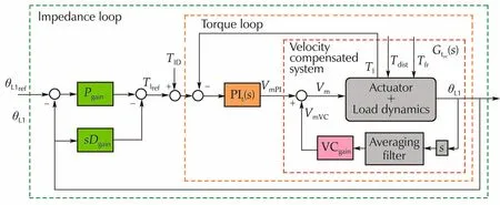
Fig.7 Block diagram of the velocity compensated system with inner torque loop(PI,orange block)outer impedance loop(PD,green blocks).The velocity compensation term(V m VC)is added to the output(V m PI)of the torque controller.
3.1 Positive feedback velocity compensation
One difficulty in the design of the torque loop controller is that the load dynamics may introduce severe limitations in the closed-loop performance of the torque loop.This problem has been largely overlooked since in m any cases the load dynamics are ignored in the analysis.In this section,a positive velocity feedback(velocity compensation)is introduced to address these limitations and improve the torque bandwidth.To exhibit the above-mentioned limitations,first of all,the system response has been considered after closing the inner velocity feedback loop.The torque transmitted to the load is measured by the torque sensor and can be expressed as

From equation(1),equation(2)and Fig.7,closing the velocity loop(without considering the averaging filter for the sake of simplicity),the transfer function from the motor voltage to the torque is given by(cf.Eq.(3.24),Ch.4,p.45 in[30]for complete derivation)

w here
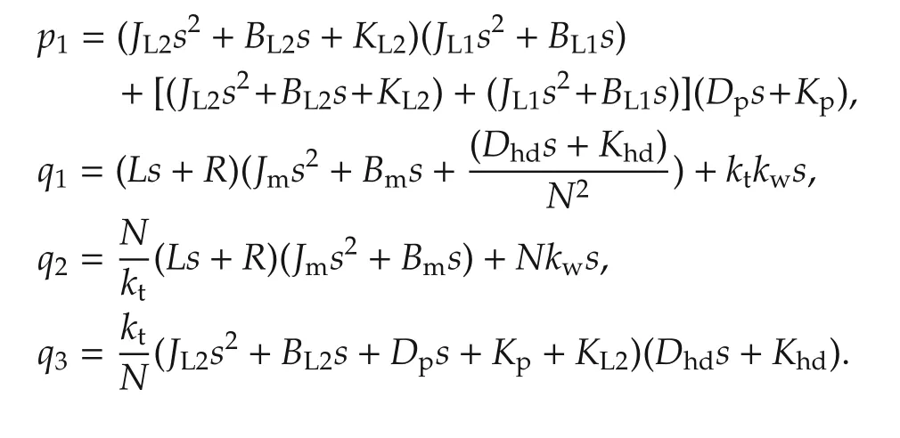
Observe that the transmission zeros in equation(3)introduced by the polynomialp1depend entirely on the load dynamics,that is the load connected at the output of the harmonic drive.When the dam ping coefficientsBL1andBL2are sm all,as is usually the case,some of these transmission zeros are very close to the stability region boundary.In the case of continuous time systems the boundary is the imaginary axis and in the case of discrete time systems this is the unit circle.Notice that the zeros may be real or com p lex depending on the value of the stiffnessKL2.These zeros impose limitations in the achievable closed-loop bandwidth w hen using a simple proportional and integral torque controller.This is because the controller pole,located at the origin,will be attracted towards the transmission zeros becoming the dominant pole of the system,thus limiting the closed-loop bandwidth of the torque loop unless very high gains are used in the torque controller.In most cases the torque loop gain will have a finite gain margin and therefore the controller gain cannot be made sufficiently large.This is m ore pronounced in digital control where the gain margin is likely to be much lower than the gain margin for a continuous time system.The effect of the velocity compensation is that these unwanted transmission zeros(polynomialp1)can be cancelled if the velocity feedback gain is chosen as VCgain=q2/sso that the termq2−VCgainsin the denominator of equation(3)is equal to zero.

The implementation of the compensator requires derivatives of the velocity signal that is often prone to quantization errors.Since this derivative is likely to be noisy the compensator has to be approximated by adding suitable filters which would add delay.An alternative solution is to use a simplified velocity compensation as presented in[31]which is obtained by discarding the derivative term s from equation(4):

This simplified velocity compensation is obtained by settingL=0 andJm=0.This means we are neglecting both the electrical dynamics and the acceleration term,which would introduce noise in the system.α is introduced as an adjustable parameter.Therefore,with equation(5),an exact cancellation of the transmission zerosp1is generally not possible.Nevertheless,even though an exact cancellation is not possible,an improvement in the closed-loop torque bandwidth can be achieved.To understand w hen and how this is possible,consider the velocity compensation given by equation(5).For the parameter values given in Table 1 and settingKL2=0,the polynomialp1has four real rootsz4<z3<z2<z1=0.The transfer function(3)also has a pole at zero.This is an unobservable pole and therefore it cancels out with the zeroz1.The second zeroz2is the closest to the imaginary axis and limits the torque bandwidth that can be achieved with a PI torque controller.Indeed,as α increases one real pole in equation(3)moves towards the stability boundary along the real axis and at some point it will become identical toz2.The value of the gain α for which this happens,is the ideal value required for cancelling out unwanted zeroz2.In this particular case,z2varies as a function of the leg inertia.Hence,it may be difficult to completely cancel out this zero for all leg configurations with a fixed value for α.However,as long as the pole in equation(3)is placed to the right of the zeroz2then the bandwidth limitation introduced by this zero is avoided(cf.Sec.3.5.3,Ch.4,p.46 in[30]).WhenKL2≠0,then the roots ofp1,which are closest to the imaginary axis,are complex(z1andz2are com p lex conjugate).As α increases two poles in equation(3)will move towards the imaginary axis as a comp lex conjugate pair but there is no value of α that will completely cancel out the unwanted zerosz1andz2.In this case the velocity compensation will not be as effective as for the case whereKL2=0.Nevertheless,it still results in an improvement of the achievable closed-loop torque bandwidth as shown in Fig.8.
Similar results can be established after discretization of the continuous time system.A final rem ark is that an alternative to overcome the limitations imposed by the unwanted zeros is to consider more comp lex controllers,for example a double integrator PII controller,or designs based on loop shaping control which introduce additional poles and zeros.The disadvantage is that tuning these com p lex controllers cannot be done without a good model for the system.
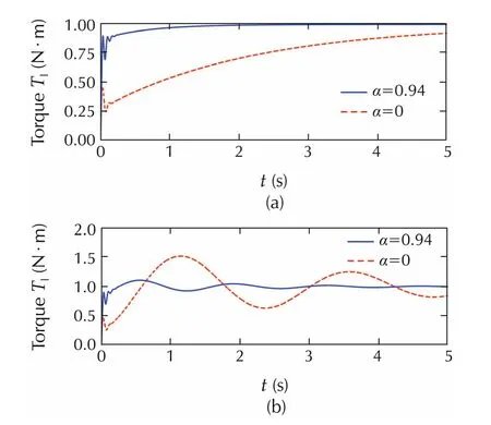
Fig.8 Simulation.Unit torque step responses with K L2=0(upper plot)and K L2=11.2N·m/rad(lower plot)for different velocity compensation gains α=0.94(So lid line)and α=0(dashed line).An extended leg inertia(J L2=0.439 kg·m2)has been considered.The use of velocity compensation significantly reduces the response time.
3.2 Torque controller design
In this section,the design of a PI torque controller is considered.An integrator is included in the controller structure to remove steady state errors w hen tracking constant torque inputs or when constant disturbances arise.The integrator is implemented in discrete time using the backward euler approximation.This controller is a lag compensator that has one zero and one pole.The analysis and design are carried out in discrete time because sampling introduces noticeable differences in comparison to the continuous time case.For example the system can become non-minimum phase even if the underlying continuous time is of minimum phase(non minimum phase system s are m ore difficult to control).The equation of the PI controller is given by

w herezis theZ-transform variable andTs=1m s is the sampling time interval;andPtandItare the proportional and integral gains to be determined.We remark that small sampling time intervals,on one hand,improve the disturbance rejection properties of the closed-loop system.However,as the sampling time interval decreases,the effects of quantization noise in the encoders become more prominent,especially when computing velocities from position measurements using simple first order differences.In addition,small sampling time intervals can introduce non-minimum phase behavior in the sampled system which is more difficult to control.The selected sampling time of 1m s is a trade-off among all these aspects.At the actual encoder resolution(80000 count/rev),the smallest velocity that can be measured with 1m s sampling time interval,is 0.0125 rad/s.
Traditionally,the design of an inner loop controller is carried out with the aim of maximizing the closed-loop bandwidth of the inner loop.However,one of the first difficulties is how to measure the bandwidth of the torque loop.The closed-loop torque bandwidth for an unconstrained system,for example when the leg is moving freely in the air,is very different from the case when the system is in contact with the ground and depends on the ground stiffness(soft versus hard).In fact,assuming that gravity is fully compensated(this meansKL2=0),the free leg motion with the torque loop closed is not internally stable(as was shown in the previous section there is a pole-zero cancellation on the stability boundary).Further,it is not obvious that maximizing the bandwidth of the torque loop is always consistent with the specifications for the outer impedance loop.In the approach presented in this paper it was decided to design the controller gains so that the torque loop gain has a phase margin larger than 30°and a gain margin larger than 12 dB for the upper and lower bounds ofJL2andKL2and with a velocity compensation gain α=0.94.This would result in a satisfactory response.In addition,the closed-loop torque response was required to be stable for all values of the velocity compensation gain α between zero and one(but the gain and phase margins can be less than 12 dB or 30°,respectively).A set of controller gains satisfying the given specifications is found by using the MATLAB SISO tool.

Changing the gain β only affects the gain of the controller but the controller zero remains fixed.This gives ample freedom to investigate the effects of increasing the torque loop gain β and hence increasing the closed-loop torque bandwidth when the outer loop specifications are considered.We must remark that,when defining the torque bandwidth,we consider that the system is free to move in the air.Then the bandwidth is the frequency where the torque amplitude decreases by−3dB respect to the reference.
3.2.1 Harmonic drive torque ripple compensation
One drawback of using a harmonic drive gearbox is that it introduces torque ripples(Tfrin(1)).The problem is related to the working principle of the gearbox that is based on the motion of an elliptic element(wave generator).This motion creates torque fluctuation with a fundamental frequency which is twice the wave generator angular velocity.While this disturbance is normally neglected in position control schemes,because it is passively filtered out by the inertia of the system,conversely it has a detrimental effect on torque control and creates vibrations and wearing of the components.A way to mitigate this problem is to add a lead/lag compensator(notch)in series to the PI controller in order to add enough phase lead at the resonance of the transfer function betweenTfrandTlw here the ripple is m ore prominent,as illustrated in Sec.3.7,Ch.4,p.50 in[30].
3.3 impedance control
An impedance controller is added as an outer loop as show n in Fig.7.The controller gainsPgainandDgainrepresent the stiffness and dam ping for the joint.The outputTlrefof the controller provides the reference torque for the inner loop:

while θL1refis the desired trajectory for the joint position.The term involving the link velocity feedback is implemented using an averaging filter to reduce the effects of encoder quantization.TID(see Fig.7)is an external compensation torque(e.g.,inverse dynamics)that can be added to remove the effects of gravity and inertia(and thus reduce position tracking errors):

wherelcomis the distance of the leg center of mass from the joint axis.For HyQ,a range of values for the impedance loop gains that is considered to be sufficient for walking,trotting and running tasks isPgain∈[1,2000]N·m/rad andDgain∈[1,50]N·m/rad.
孔庆东的解读偏重于揭露鲁迅平民化的一面,这不仅将一个完整、丰富、多维的鲁迅形象展示给大众,同时幽默的语言与故事化的讲述风格让观众感到轻松。但在《百家讲坛》对鲁迅形象进行传播、重构的过程中,仍然存在一些问题。
4 Stability regions
The analysis here is limited to the abduction-adduction electric joint of HyQ with a variable load inertia that depends on the configuration of the leg joints.In particular,given a range of impedance parameters,PgainandDgain,this analysis will assess how the region of closed-loop stability is affected by varying the torque controller gain(β),the velocity compensation gain(α),the number of samples used in the averaging filter(Nav)and the sampling time(Ts).
The analysis has been performed by varying the stiffnessPgainbetween 1 and 20000N·m/rad and the dampingDgainbetween 1 and 50.The upper-bound for the stiffness was chosen such that we could determine the boundary for the stability and passivity regions and is way beyond the maximum value used in locomotion.The stability of the overall system is determined by computing the closed-loop eigenvalues and checking that they are inside the unit circle.In addition,when closed-loop stability is attained,the region where the phase margin is less than 30°can be determined.These calculations were carried out in MATLAB using the mathematical model presented in Section 2.The results are displayed in Figs.9–12 where the white area corresponds to the stable region;light grey is a stable region with a phase margin of less than 30°and the dark area is the unstable region;and crosses and squares denote unstable and stable experimental points respectively.In the analysis all the regions have been computed for the leg in stretched configurationJL2=0.439kg·m2unless it is otherwise stated.
Fig.9 show s that as the torque controller gain increases,the unstable region for low stiffness and dam ping decreases but the unstable region for large stiffness and/or large dam ping increases.This clearly illustrates that increasing the torque loop bandwidth may not be consistent with the(stability)requirements for the outer impedance loop.This can be explained if we consider that for any given system and controller architecture,there is a limit on the maximum loop gain that can be achieved,beyond which stability is not ensured and performance degrades.In a nested architecture both loops contribute to the loop gain.If the loop gain contribution from the torque loop increases(e.g.,the gain β increases),then the contribution from the impedance loop should reduce otherwise closed-loop stability would be lost.
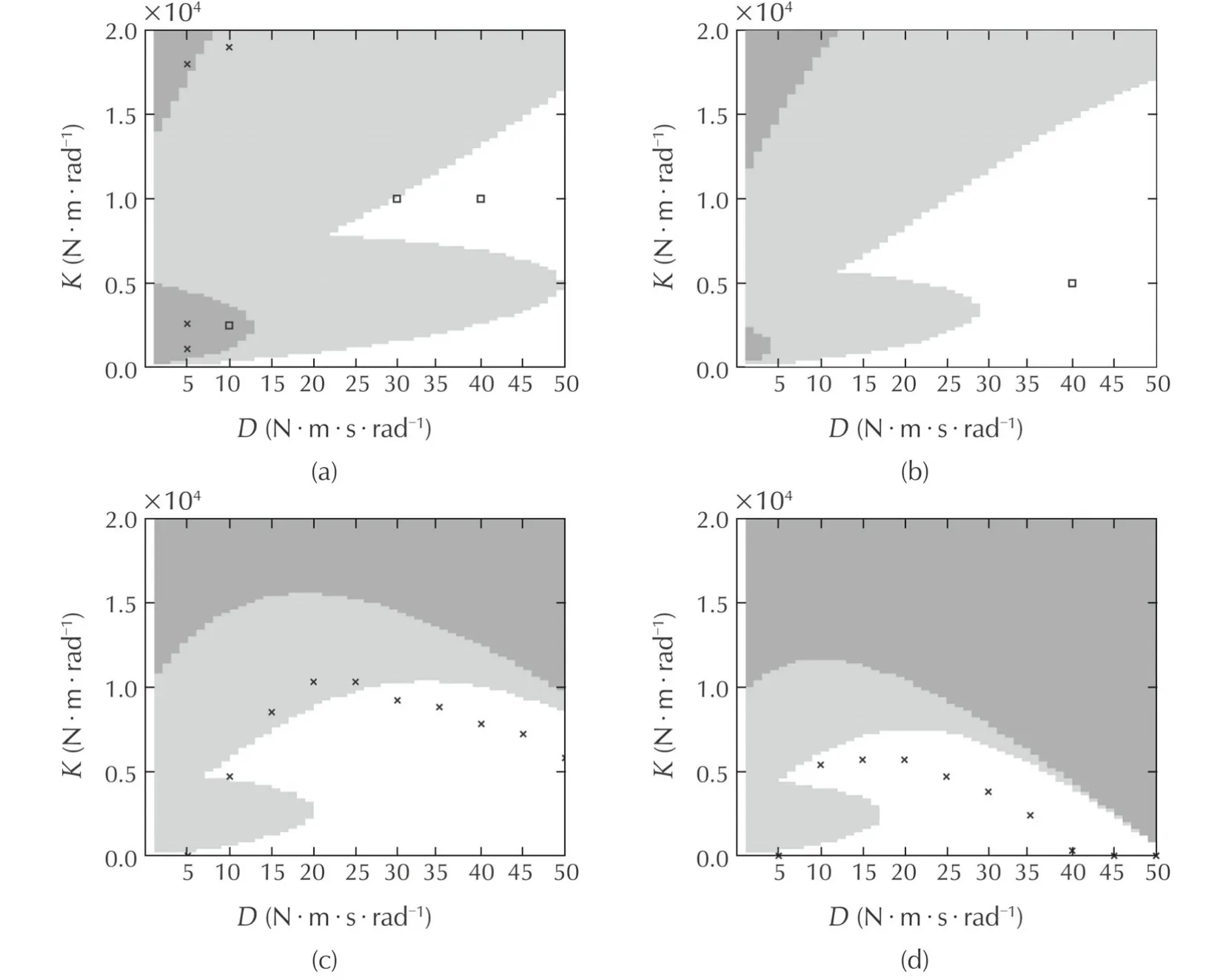
Fig.9 Stability regions varying the torque controller gain β(with α=0.94,N av=4 and T s=1m s).(a)β=1.(b)β=2.(c)β=4.(d)β=6.
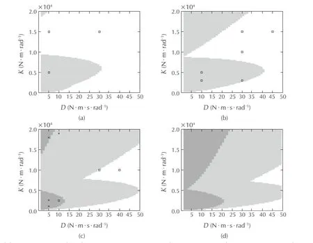
Fig.10 Stability regions varying the velocity compensation gain α(with β=1,N av=4 and T s=1m s).(a)α=0.(b)α=0.5.(c)α=0.94.(d)α=1.2.
From Fig.10(a)–(c)it is clear that increasing the velocity compensation gain results in an increasing instability region.Once more this gives further evidence that as the torque loop bandwidth increases,the outer loop may become unstable.The effects of increasing the number of samples(Nav)in the velocity averaging filter are shown in Fig.11.Averaging a large number of samples enlarges the instability region for low stiffness values but the unstable region for high stiffness and low dam ping decreases in size.Fig.12 clearly show s that for a large sampling time interval the region for instability is the largest both for low and high dam ping and stiffness.The region w here the phase margin is less than 30°also increases as the sampling time increases.For low leg inertia configuration in Fig.12(d)the instability region for low dam ping and low stiffness increases but the unstable region decreases for low dam ping and large stiffness.The region with a phase margin smaller than 30°is also larger for the low inertia configuration.
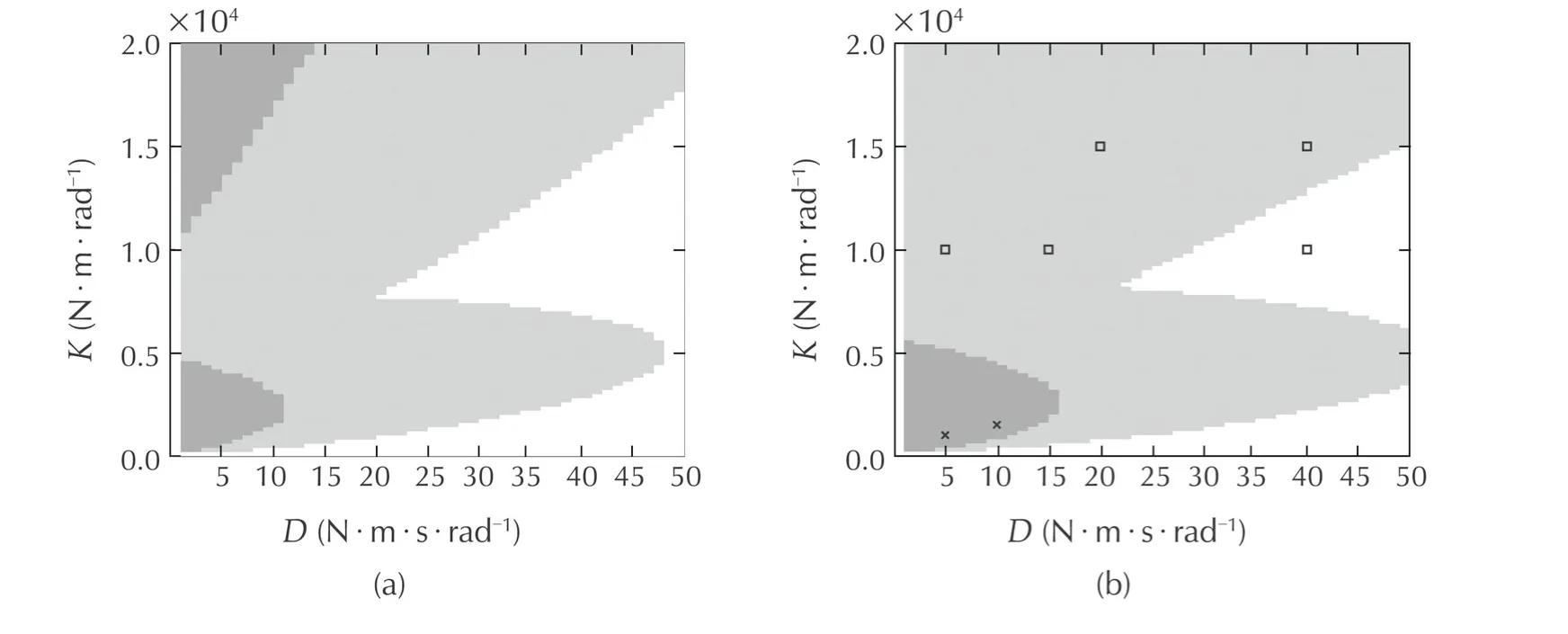
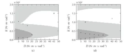
Fig.11 Stability regions varying number of sam ples N av of the link velocity filter(with β=1,α=0.94 and T s=1ms).(a)N av=1.(b)N av=10.(c)N av=20.(d)N av=50.
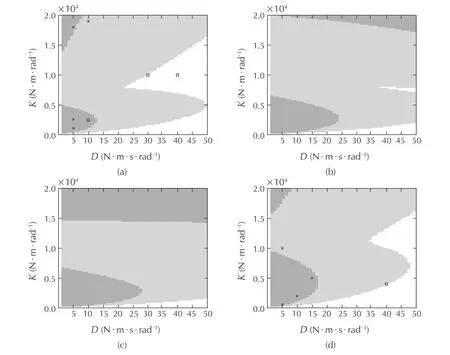
Fig.12(a)–(c)Stability regions varying the sampling times T s(with β=1,N av=4,α=0.94).(d)Stability region for retracted leg(lower inertia)J L2=0.129 kg·m 2(with β=1,α=0.94,N av=4 and T s=1m s).(a)T s=1m s.(b)T s=6m s.(c)T s=8m s.(d)J L2=0.129 kg·m 2.
To determine the stability regions experimentally is not an easy task because it would involve a vey large number of experiments. Even only finding the stability boundaries is not a simple task. Several experimental tests were carried out to validate the analytical results predicted by the model. The adopted methodology was to start from valuesPgainandDgainwell inside the stable region and change the parameters in small steps until the instability was triggered.This enabled us to get a rough idea of the boundary of the stability region.The experi-mental results are displayed in Figs.9–12,where crosses and squares denote unstable and stable points respectively.with the exception of Fig.9(c)and(d),overall the experimental tests are consistent with the analytical calculations.Figs.9(b),10(a),10(b)and 11(b)are fully in agreement with the theoretical results.For test points near the stability boundaries inconsistencies are present suggesting that the model lacks accuracy from a quantitative point of view but qualitatively it is correct.The experimental results show n in Fig.9(c)and(d)are quite different from the expected outcome.Even though a precise explanation is currently not available,the authors have several possible hypothesis for these discrepancies:the experimental set-up might have reached some limiting conditions,which invalidate the linear analysis(for example by generating motor voltages that exceed the capabilities of the motor drive electronics,or by generating reference torques that exceed the range of the torque sensor).Their investigation is part of future work.
5 Passivity analysis
Another question of interest is whether the closed loop system remains stable when it interacts with a passive environment.It is w ell-know n that a strictly passive system,connected to any passive environment,is necessarily stable[32].Thus,since most terrain surfaces are passive,to ensure a stable contact with the environment also the robot joints have to be passive.This section therefore analyzes them a in factors that influence passivity.Stating that a system is passive,is equivalent to saying that the system is intrinsically dissipative.This is not always the case when compliance is obtained actively,where the com pliant behavior is emulated by controlled actuators.In this case,the controller gains can destroy passivity.The requirement to ensure this type of stability for the robot interacting with the environment is the following:the port of interaction between the system and the environment,i.e.the driving port impedance,has to be passive.For linear time invariant system s this is a necessary and sufficient condition,but it is only a sufficient condition for nonlinear system s.LetZ(s)denote the driving port impedance transfer function.ThenZ(s)is passive if and only if it is positive real[33].In[16]and[34]it has been shown that this is equivalent to:
1)Z(s)has no poles in ℜ(s)>0;
2)the phase ofZ(s)lies between−90 and 90°.
For sampled data control system s,Colgate[16]has suggested an approximate method based on computing the corresponding discrete time transfer functionZ(z),assuming that the port of interaction is also sampled.The phase ofZ(z)is computed and corrected by subtracting ωTs/2 rad,whereTsis the sampling time interval.Although many studies have been carried out for analyzing the passivity of sampled-data system s[35],there is still a lack of information about the influence of the closed loop torque control bandwidth on the combinations of stiffness and dam ping that can be passively rendered(in the field of haptics calledZ-width)[16].Therefore,this section will show that the torque loop performance plays an important role in determining the range of passively achievable impedance values.The discrete time transfer functionZ(z)(impedance)has been computed from the link velocity˙θL1to the load disturbanceTdist.The transfer function has been computed for two cases:one for the torque loop(with velocity compensation)and one for the system after closing the outer impedance loop.Then the above-mentioned phase correction is applied to include the fact that the system is sampled.In the approach presented in this paper the analysis of passivity has been done by varying several parameters to have a better understanding of their influence:the gain of the PI torque controller(by varying the gain β in equation(7)),the velocity compensation gain α,the sampling timeTs,and the number of samplesNavof the averaging filter of the link velocity.For each set of parameters the analysis was performed by first checking the stability ofZ(z)and then verifying that the corrected phase ofZ(z)w as in the range±90°for frequencies up to the Nyquist frequency.If these conditions are not satisfied thenZ(z)is not passive for the particular set of parameter values.The results of this analysis are summarized in Table 2.
In this table the nominal set of parameters are α=0.94,Nav=4 samples,leg inertiaJL2=0.439kg·m2,Pt=0.38 andIt=18.The overall(impedance+torque loop)system is always passive for low impedancesPgain=200,Dgain=10 while passivity might be destroyed when the torque controller gain β(and so the torque bandwidth)increases or the sampling frequency decreases.In particular it can be noticed that w hen the torque gain is larger than or equal to 4 the closed-loop system with the impedance loop becomes unstable.This is a clear indication that increasing the bandwidth of the torque loop is not always consistent with the requirements of the position loop.When only the torque loop is closed the system is almost never passive except for low values of α.The table show s that the velocity compensation is the key parameter affecting the passivity if the torque loop alone is considered.In particular w hen the amount of velocity compensation increases,the inner torque loop becomes not passive and therefore the torque control system alone can become unstable w hen the leg interacts with some environments.
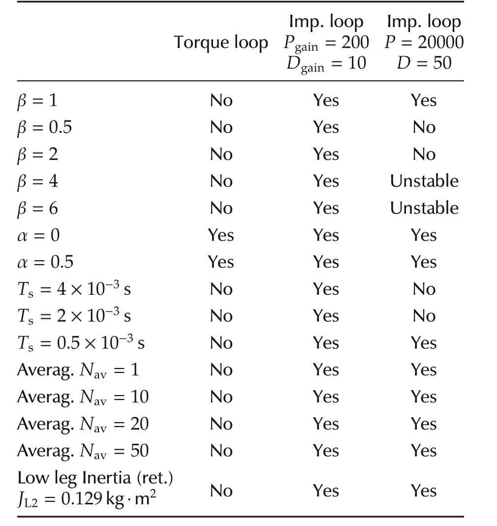
Table 2 Passivity.
Further analysis showed that the system(without closing the impedance loop)becomes unstable if the leg is in contact with an environment with a stiffnessKL2between 72N·m/rad and 3500N·m/rad.This has been verified with experimental tests using the test setup depicted in Fig.13 by commanding a leg motion to have an impact against a physical spring.This spring is positioned in order to create a certain stiffnessKL2.
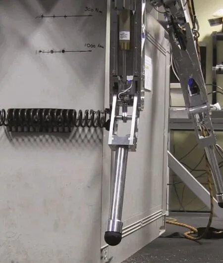
Fig.13 experimental setup for passivity tests.The rotational stiffness K L2 is obtained by positioning a linear spring at a certain distance from the HAA axis.
Fig.14 show s the phase ofZ(z)when only the torque loop is closed(β=1 and α=0.94)and when both the torque and the impedance loops are closed(Pgain=200,Dgain=10).The curves illustrate that,in the case of the torque loop alone,the phase ofZ(z)exceeds 90°between 10 and 50 rad/s,indicating the loss of passivity,while,when the outer loop is closed,the phase always remains within±90°,demonstrating that the passivity property is ensured as indicated in Table 2.
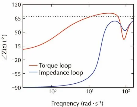
Fig.14 Simulation.Phase p lot of the driving port impedance Z(z)when only the torque loop is closed(β=1,α=0.94)and when both the torque and the impedance loops are closed(P gain=200,D gain=10).The black line show s the limit of 90°.
6 Conclusions and future work
This paper presented a methodology for designing joint impedance controllers based on an inner torque loop and a positive velocity feedback loop.In particular,it was shown that the positive velocity feedback can be used to increase the closed-loop bandwidth of the torque loop without the need of a com p lex controller.It has been demonstrated that besides the sampling frequency and filtering,the bandwidth of the torque loop has a strong influence on the range of impedance parameters(Z-width)that exhibit a passive and/or stable behavior.Indeed,larger inner loop bandwidth can be beneficial for disturbance rejection and to improve the tracking of the impedance(enlarge the range of frequencies for which the desired impedance is emulated by the system)but,at the same time,it can reduce the region of stable impedance parameters.This fact can limit the performance and versatility of a robot.Thus,the highest possible bandwidth for the torque loop might not be the best solution for all situations.It is therefore important to find a balance between the torque loop requirements(e.g.,to have a good torque tracking)and the stability/passivity specifications of the overall system.Furthermore,it has become evident that,even for simple controllers,the design problem is challenging and that there are competing trade-offs to consider when selecting the controller gains.
This suggests that there is a need for a problem formulation that can encompass the design objectives in a more systematic and generic framework.There are a number of areas that need further research and are left for future work.Adaptive schemes(e.g.,gain scheduling)can be developed to modify the torque controller gains to satisfy the constraints of stability/passivity given by the desired impedance parameters specified by the system designer.The torque gains can also be modified depending on the load inertia variations that is changing with the leg configuration.In addition,varying the location of the PI torque controller zero can provide improvements in performance.The torque controller architecture can also be enhanced to reduce the effects of torque ripples arising in the gear transmission system(drive jitter).Since increasing the torque controller gain has been shown to be detrimental,this option for mitigating the drive jitter can be discarded and more different solutions must be found.Finally,there is a need to develop strategies to quantify the range of impedances that are required for specific tasks.At present there are some guidelines that only provide qualitative results,for example a high stiffness(Pgain)is specified when there is contact with a com pliant environment and the positioning accuracy is important.On the other hand,a low stiffness is used to maintain small contact forces or when the environment is stiff.Similarly,large dam ping values(Dgain)are needed to reduce vibrations or to quickly dissipate energy.Future work also encompasses an extension of the methodology presented in this paper to include multi-degree of freedom system s.
References
[1]G.A.Pratt.Low impedance walking robots.Annual Meeting of the Society-for-Integrative-and-Comparative-Biolog,Chicago:Oxford University Press,2002:174–181.
[2]J.Buchli,M.Kalakrishnan,M.Mistry,et al.Compliant quadruped locomotion over rough terrain.IEEE/RSJ International Conference on Intelligent Robots and System s,St Louis:IEEE,2009:814–820.
[3]N.Tsagarakis,S.Morfey,G.Medrano-Cerda,et al.Com pliant humanoid COMAN:optimal joint stiffness tuning for modal frequency control.IEEE International Conference on Robotics and Automation,Karlsruhe:IEEE,2013:673–678.
[4]N.Paine,S.Oh,L.Sentis.Design and control considerations for high-performance series elastic actuators.IEEE/ASME Transactions on Mechatronics,2014,19(3):1080–1091.
[5]A.Albu-Sch¨affer,S.Haddadin,C.Ott,et al.The DLR lightweight robot:Design and control concepts for robots in hum an environments.Industrial Robot:An International Journal,2007,34(5):376–385.
[6]D.P.Ferris,M.Louie,C.T.Farley.Running in the real world:adjusting leg stiffness for different surfaces.Proceedings of the Royal Society B:Biological Sciences,1998,265(1400):989–994.
[7]N.Hogan.impedance control:An approach to manipulation–Part II:Implementation.Journal of dynamic System s,Measurement,and Control,1985,107(1):8–16.
[8]O.Khatib.A unified approach for motion and force control of robot manipulators:The operational space formulation.Journal of Robotics and Automation.1987:43–53.
[9]M.H.Raibert,J.J.Craig.Hybrid position/force control of manipulators.Journal of dynamic System s,Measurement,and Control,1981,103(2):126–133.
[10]J.Pratt,C.Chew,A.Torres,et al.Virtual model control:An intuitive approach for bipedal locomotion.International Journal of Robotics Research,2001,20(2):129–143.
[11]W.Bosworth,S.Kim,N.Hogan.The effect of leg impedance on stability and efficiency in quadrupedal trotting.IEEE/RSJ International Conference on Intelligent Robots and System s,Chicago:IEEE,2014:4895–4900.
[12]G.Pratt,M.williamson.Series elastic actuators.IEEE/RSJ International Conference on Intelligent Robots and System s,Pittsburgh:IEEE Computer Society,1995:399–406.
[13]T.Boaventura,C.Semini,J.Buchli,et al.dynamic torque control of a hydraulic quadruped robot.International Conference on Robotics and Automation,St.Paul:IEEE,2012:1889–1894.
[14]M.Hutter,M.Hoepflinger,C.Gehring.Hybrid operational space control for com pliant legged system s.Proceedings of Robotics:Science and System s,Sydney:M IT Press,2012:150–157.
[15]J.Mehling,J.Colgate,M.Peshkin.Increasing the impedance range of a haptic display by adding electrical dam ping.The 1st Joint Eurohaptics Conference and Symposium on Haptic Interfaces for Virtual Environment and Teleoperator System s,Pisa:IEEE Computer Society,2005:257–262.
[16]J.E.Colgate.Coupled stability of multiport system s–theory and experiments.Journal of dynamic System s,Measurement and Control,1994,116(3):419–428.
[17]G.Ellis.Control System Design Guide.2nd ed.London:Academic Press,2000.
[18]F.Janabi-Sharifi,V.Hayward,C.-S.Chen.Discrete-time adaptive windowing for velocity estimation.IEEE Transactions on Control System s Technology,2000,8(6):1003–1009.
[19]A.Albu-Schaffer,C.O tt,G.Hirzinger.A unified passivity-based control framework for position,torque and impedance control of flexible joint robots.The 12th International Journal of Robotics Research,San Francisco:SAGE Publications Ltd.,2007:23–39.
[20]A.Albu-Schaffer,C.Ott,G.Hirzinger.A passivity based Cartesian impedance controller for flexible joint robots–Part II:Full state feedback,impedance design and experiments.International Conference on Robotics and Automation,New Orleans:IEEE,2004:2666–2672.
[21]N.Hogan,E.Colgate.Stability problems in contact tasks.Robotics Review,Cam bridge:M IT Press,2004:339–348.
[22]H.Karerooni,T.B.Sheridan,P.K.Houpt.Robust com pliant motion for manipulators–Part I:The fundamental concepts of com pliant motion,Part II:Design method.Journal of Robotics and Automation,1986,2(2):83–105.
[23]D.A.Lawrence.impedance control stability properties in comm on implementations.International Conference on Robotics and Automation,Philadelphia:IEEE Computer Society,1988:1185–1190.
[24]S.P.Buerger,N.Hogan.Complementary stability and loop shaping for improved hum an-robot interaction.IEEE Transactions on Robotics,2007,23(2):232–244.
[25]H.Mehdi,O.Boubaker.Stiffness and impedance control using Lyapunov theory for robot-aided rehabilitation.International Journal of Social Robotics,2011,4(1):107–119.
[26]N.Yasrebi,D.Constantinescu.Extending the Z-width of a haptic device using acceleration feedback.Proceedings of the 6th EuroHaptics International Conference,Madrid:Sp ringer,2008:157–162.
[27]C.Semini,N.G.Tsagarakis,E.Guglielmino,et al.Design of Hy Q–a hydraulically and electrically actuated quadruped robot.Journal of System s and Control Engineering,2011,225(I6):831–849.
[28]M.Focchi,T.Boaventura,C.Semini,et al.Torque-control based com pliant actuation of a quadruped robot.Proceedings of the 12th IEEE International Workshop on Advanced Motion Control,Sarajevo:IEEE,2012:DOI 10.1109/AMC.2012.6197133.
[29]Y.Hori,H.Iseki,K.Sugiura.Basic consideration of vibration suppression and disturbance rejection control of multi-inertia system using SFLAC(state feedback and load acceleration control).IEEE Transactions on Industry Applications,1994,30(4):889–896.
[30]M.Focchi.Strategies to improve the impedance Control Performance of a Quadruped Robot.Ph.D.thesis.Italy:Istituto Italiano di Tecnologia,2013.
[31]T.Boaventura,M.Focchi,M.Frigerio,et al.On the role of load motion compensation in high-performance force control.IEEE/RSJ International Conference on Intelligent Robots and System s,Algarve:IEEE,2012:4066–4071.
[32]E.Colgate,N.Hogan.An analysis of contact instability in term s of passive physical equivalents.IEEE International Conference on Robotics and Automation,Scottsdale:IEEE Computer Society,1989:404–409.
[33]B.D.O.Anderson,S.Vongpanitlerd.Network Analysis and Synthesis:A Modern System s Theory Approach.New York:Dover Publications,2006.
[34]J.E.Colgate.The Control of dynamically Interacting System s.Ph.D.thesis.Cambridge:Massachusetts Institute of Technology,1986.
[35]J.E.Colgate,G.G.Schenkel.Passivity of a class of sampled-data system s:Application to haptic interfaces.Journal of Robotic System s,1997,14(1):37–47.
猜你喜欢
杂志排行
Control Theory and Technology的其它文章
- Fault detection for nonlinear discrete-time system s via deterministic learning
- A necessary and sufficient stabilization condition for discrete time-varying stochastic system s with multiplicative noise
- Lyapunov stability and generalized invariance principle for nonconvex differential inclusions
- Convergence,stability and robustness analysis of the OFEX controller for high-speed networks
- Adaptive control for an uncertain robotic manipulator with input saturations
