Influence of Helix Angle on Stability of Milling Flexible Parts
2016-02-09,,
, ,
College of Mechanical and Electrical Engineering, Nanjing University of Aeronautics and Astronautics, Nanjing 210016, P.R.China
Influence of Helix Angle on Stability of Milling Flexible Parts
MuhammadMasudAkhtar,HuangXiang,ChenWenliang*
College of Mechanical and Electrical Engineering, Nanjing University of Aeronautics and Astronautics, Nanjing 210016, P.R.China
(Received 18 October 2015; revised 20 February 2016; accepted 5 March 2016)
Geometry of end mill cutters plays a vital role in the stability of the flexible parts milling. The present study considers helix angle and number of flutes. Multi-frequency solution is established to draw stability Lobe diagram(SLD) for different helix angles and number of flutes. SLD for the two cases shows that the greater the value of helix angle, the more stable the milling process will be, and conversely increasing the number of flutes degrades the stability of flexible parts milling. A simple empirical methodology is adopted to employ the inclined plane workpiece geometry offering a gradual increase of the axial depth of cut in the feed direction. Surface roughness is used as a measure of stability. Test results corroborate the model conclusions very well.
helix angle; flute; end mill cutter; flexible parts milling; stability
0 Introduction
High efficiency products in modern industries like aerospace, aircraft and automobile guarantee the needed components with thin sections, which can greatly reduce structural stiffness. However, the machining of these thin sectioned parts presents a very difficult condition to keep stability. With HSM the metal removal rate increased dramatically through a combination of large axial depths of cut and high spindle speeds. One limitation on the allowable axial depth is regenerative chatter. Chatter is the most obscuring phenomenon and considerable research has been documented regarding the prediction, control and elimination of chatter.
Many out-of-process and in-process techniques have been established to suppress, control and predict chatter. SLD stands at the border between a stable cut (i.e. no chatter) and an unstable cut (i.e. with chatter) in terms of the axial depth-of cut as a function of the spindle speed. Research in the area of chatter dates back to as early as 1906 when Taylor stated that chatter is the ″most obscure and delicate of all problems facing the machinist″[1]. Other pioneering works in the field of chatter vibration are nominated to Tlusty et al.[2], Merritt[3], Sridhar et al.[4]. A study shows that presently Altintas, Budak and Tlusty are the key stakeholders in the business of chatter[5].
Remarkable contribution in the research of workpiece vibrations in thin walled parts have been made by Budak[6-7], Seguy et al.[8], Thevenot[9], Song et al.[10], Tang and Liu[11],Davies and Balachandran[12], and Adetoro et al.[13]. The influence of mill helix angle on stability was first considered by Zatarain et al.[14]. Later Zatarain et al.[15]analyzed the concept of directional factors for chatter stability in milling including the effect of the helix angle. Shirase and Altintas[16], Budak[17-18], Sims et al.[19], Turner et al.[20], Yusoff et al.[21]demonstrated in their work that with variable pitch and variable helix milling tools the stability of the milling improved by disrupting the regenerative effect.
In the study addressed here the milling stability of flexible workpiece has been investigated under the influence of helix angle and number of flutes of end mill cutter by considering the improved helix angle model for flexible parts presented by Masud[22]in which very small changes in the initial and final immersion positions of the cutter arc segment were contemplated, to reflect the actual cutting conditions. Multi-frequency solution of the proposed model was obtained. Stability lobe diagram was constructed for variable helix angles and variable number of flutes. An increase in helix angle showed improved stability as compared to low helix angle values. Stability lobe diagram for variable number of flutes showed that the stability of the flexible parts milling increased with fewer number of flutes whereas increasing the number of flutes degraded the stability of flexible parts. A simple empirical methodology employing the inclined plane workpiece geometry was used to validate the model results. The inclined plane workpiece geometry offered the increase of axial depth of cut along the length of cut enabling varying stability condition for one spindle speed. Surface roughness was measured at different points along the cut as a gauge of stability of the cutting process, hence eliminating the need of sophisticated analytical tools and equipment like, impact hammers, piezoelectric transducers, specific software, and sensors for chatter detection.
1 Chatter Stability Model
As shown in Fig.1, the milling cutter withNteeths and the workpiece are considered to obtain flexibility in feed (x-direction), normal (y-direction) and spindle (z-direction) directions. φjis the immersion angle of thejth teeth measured from they-direction. Ω (r/s) is the spindle speed. Tangential (dFt,j(φ,z)), radial (dFr,j(φ,z)), and axial (dFa,j(φ,z)) forces acting on a differential flute element with height dz(see Fig. 2) yield as
(1)
where φj(z)is the immersion angle at the axial distancez. φj(0)=φ+j·φp, φj(z)=φ+j·φp-kβz,kβ=(2tanβ)/D. β is the helix angle andDthe effective diameter of the cutting tool. The dynamic chip thicknessi
hj(φ,z)=gi(φ)[(f+Δx+Δu)sinφj(z)+
(Δy+Δv)cosφj(z)]
(2)
where f is the feed per tooth,Δx=x(t)-x(t-T), Δy=y(t)-y(t-T)and Δu=u(t)-u(t-T), Δv=v(t)-v(t-T)are the dynamic displacements of the cutter and workpiece at the previous and the present tooth periods, respectively.
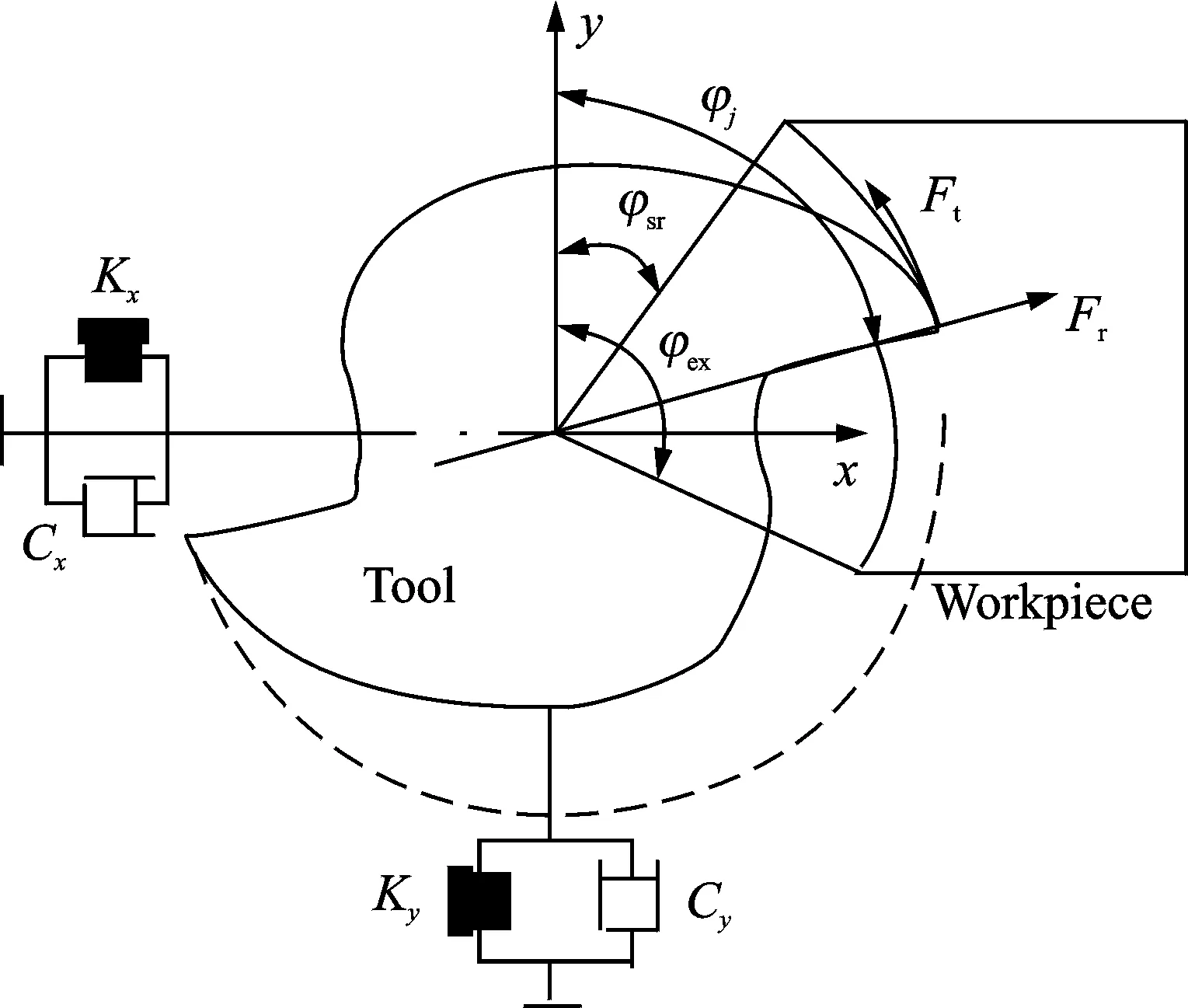
Fig.1 Dynamic model of milling

Fig.2 Helical end mill and its thin disk element
The function gi(φ) is a unit step function to determine whether the tooth is in or out of cut, that is
(3)
where φstand φexare the start and the exit immersion angles of the cutter, respectively. The elemental forces in feed (x), normal (y) and axial (z) directions are
(4)
Total cutting force produced by the flute is calculated by an integration of the differential cutting forces along the in-cut-portion of the flutejat each plane alongzdirection (5). Three distinct ways of interaction between immersion section of the cutter arc segment and a helical toothjare shown in Fig.3.
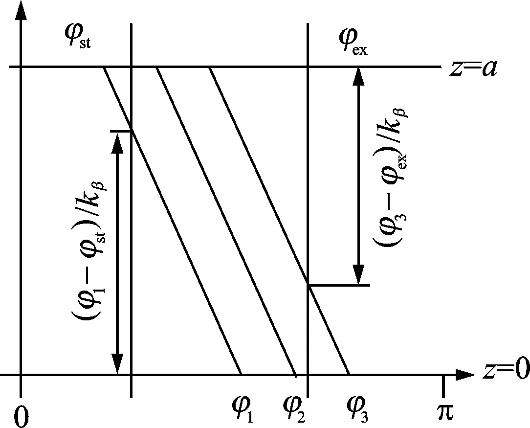
Fig.3 Helical flute-part ace integration zones

(5)
AssumingKte=Kre=Kae=0, and neglecting the axial force, the following equations can be obtained
(6a)
(6b)
where ε1=sin2φ1,j-sin2φst, ε2=2φst-2φ1,j,ε3=cos2φ1,j-cos2φst,ε4=sin2φ2,j+sin2(kβα-φ2,j),ε5=cos2φ2,j+cos2(kβa-φ2,j), ε6=sin2φex+sin2(kβa-φ3,j),ε7=2φ3,j-2φex-2kβa,ε8=cos2φex-cos2(kβa-φ3,j),Kt=Ktc,Kr=Krc/Ktc,φi,j=φi+jφp-KβZ.
The cutting forces contributed by all flutes are calculated and summed to obtain the total instantaneous forces on the cutter at immersionφ
(7)
Converting Eq.(7) into matrix form as follow
(8)
where
F=[FxFy]T
Converting Eq.(6) from time domain to frequency domain
(9)
where ″*″ denotes the convolution integral.Δ(ω) = (1-e-iωT)Φ(ω)F(ω) is the displacement/regenerative vector;Φ(ω) is the sum of the ″Frequency Response Function″ (FRF) matrices of the tool/cutter and of the workpiece. The periodic directional matrix can be expanded into Fourier series

(10a)

(10b)
Further multi-frequency solution is established to obtain the limiting depth of cut a as
(11)
2 Simulations
For simulations purpose end mill cutter of 2 flute, 12 mm diameter, 30° helix angle end mill cutter was used. Dynamic parameters of cutter inXandYdirections are shown in Table 1. The workpiece transfer function was identified in the normal direction (Y), in Table 2, as the dynamics in the feed direction (X) can be neglected due to its relative magnitude. The cutting coefficients of Al 7075,Kt= 999.28 MPa,Kr= 426.4 MPa were obtained[23].

Table 1 Tool dynamic parameters in X and Y directions
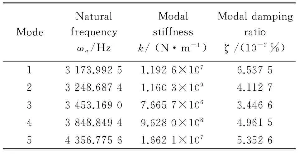
Table 2 Workpiece dynamic parameters in Y direction
(1) Helix Angle
Stability Lobe diagram(SLD) drawn for different helix angle is shown in Fig. 4. The simulation of the proposed model shows that helix angle affects the stability of flexible parts milling. An increase in helix angle shows improved stability and vice versa.
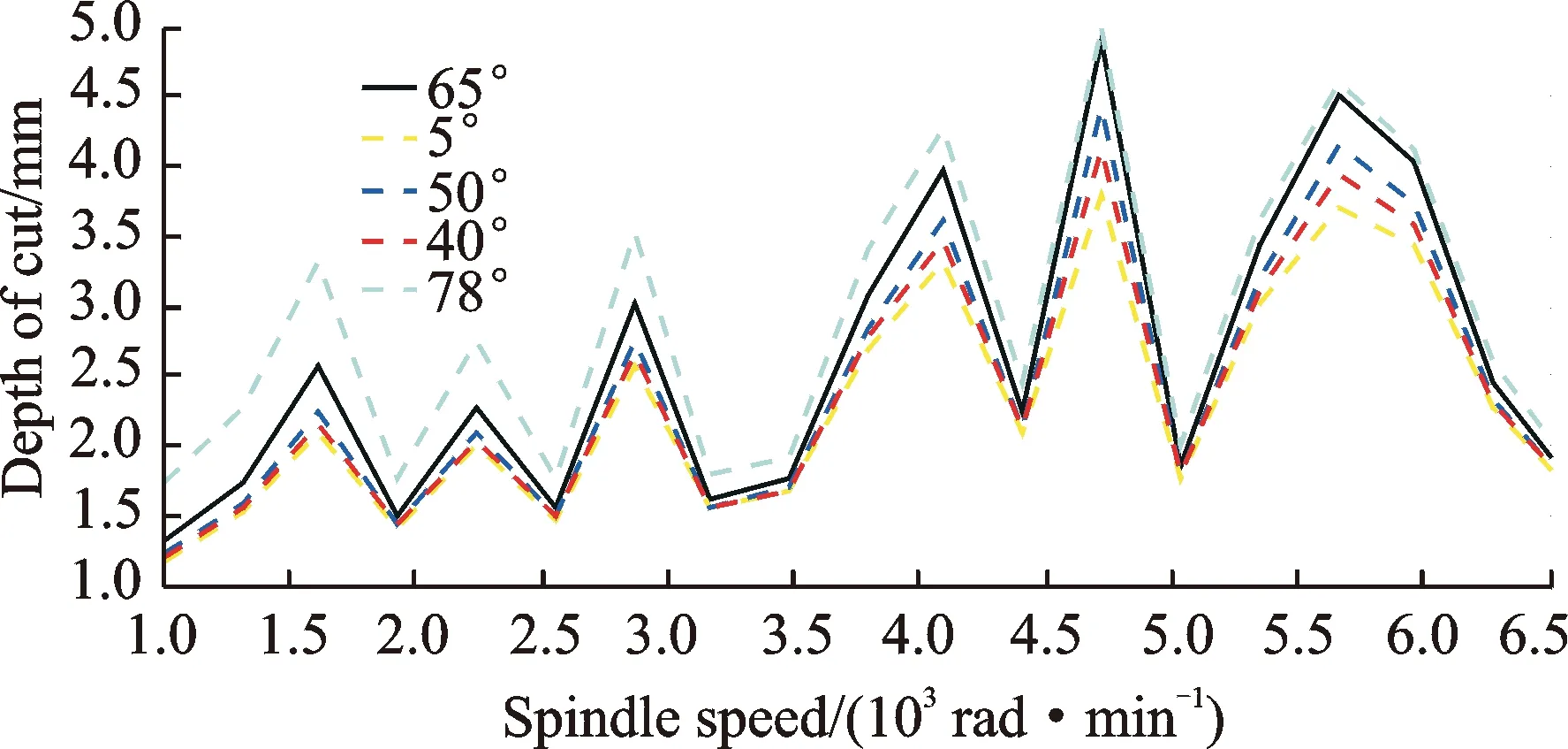
Fig.4 SLD of helix angle
(2) Number of flutes
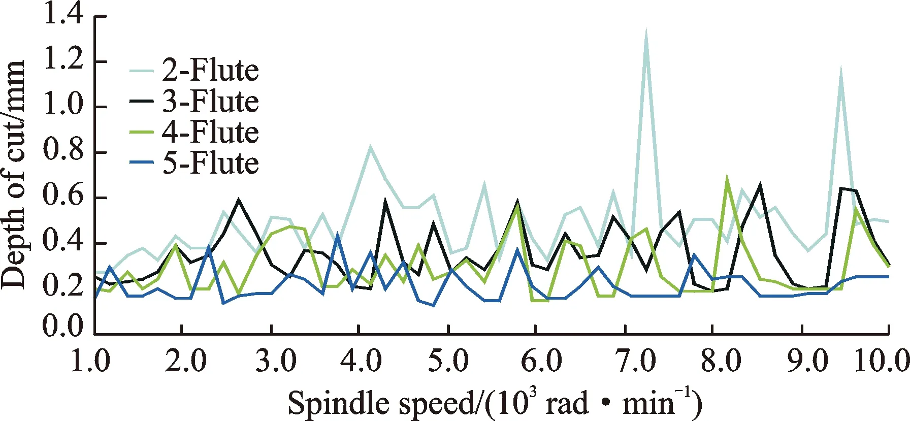
Fig.5 SLD of number of flutes
SLD drawn for different number of flutes is shown in Fig.5. The simulation shows that increasing the number of flutes degrades the stability of flexible parts milling where as an end mill cutter with fewer flutes improves the stability of the flexible parts milling.
3 Experimental Verification
In order to verify the simulation, a simple experimental methodology was adopted. A thin walled Aluminum 7075 workpiece 4 mm thick (Fig.6) of inclined geometry offering a gradual increase of the axial depth of cut in the feed direction was used. Experimental setup is shown as Fig.7.For each case of variable helix angle and number of flutes, two different values of end mill cutter were used. Test for each end mill cutter was performed with three sets of spindle speed, i.e. 2 000, 3 000 and 4 000 r/min on a three axis CNC milling machine. In order to ensure the same stability conditions among each test, following conditions were met:
·Workpiece of same geometry was used.
·Torque wrench was used to apply the same clamping force on each test piece by clamping vice.
·Same tool holder was used and same overhang of the milling cutter was ensured.
·To analyze the two different cutters same cutting parameters i.e. spindle speed, feed per revolution and RDOC were ensured.
Surface roughness of the test specimen was measured as a Gauge to compare the stability of the two different cases. Stylus type surface roughness measuring instrument was used to measure the surface roughness of the test piece at different points along the cut. Large cut-off values i.e. 2.5 mm was employed to identify the chatter marks on the machined surface[24].

Fig.6 Inclined workpiece
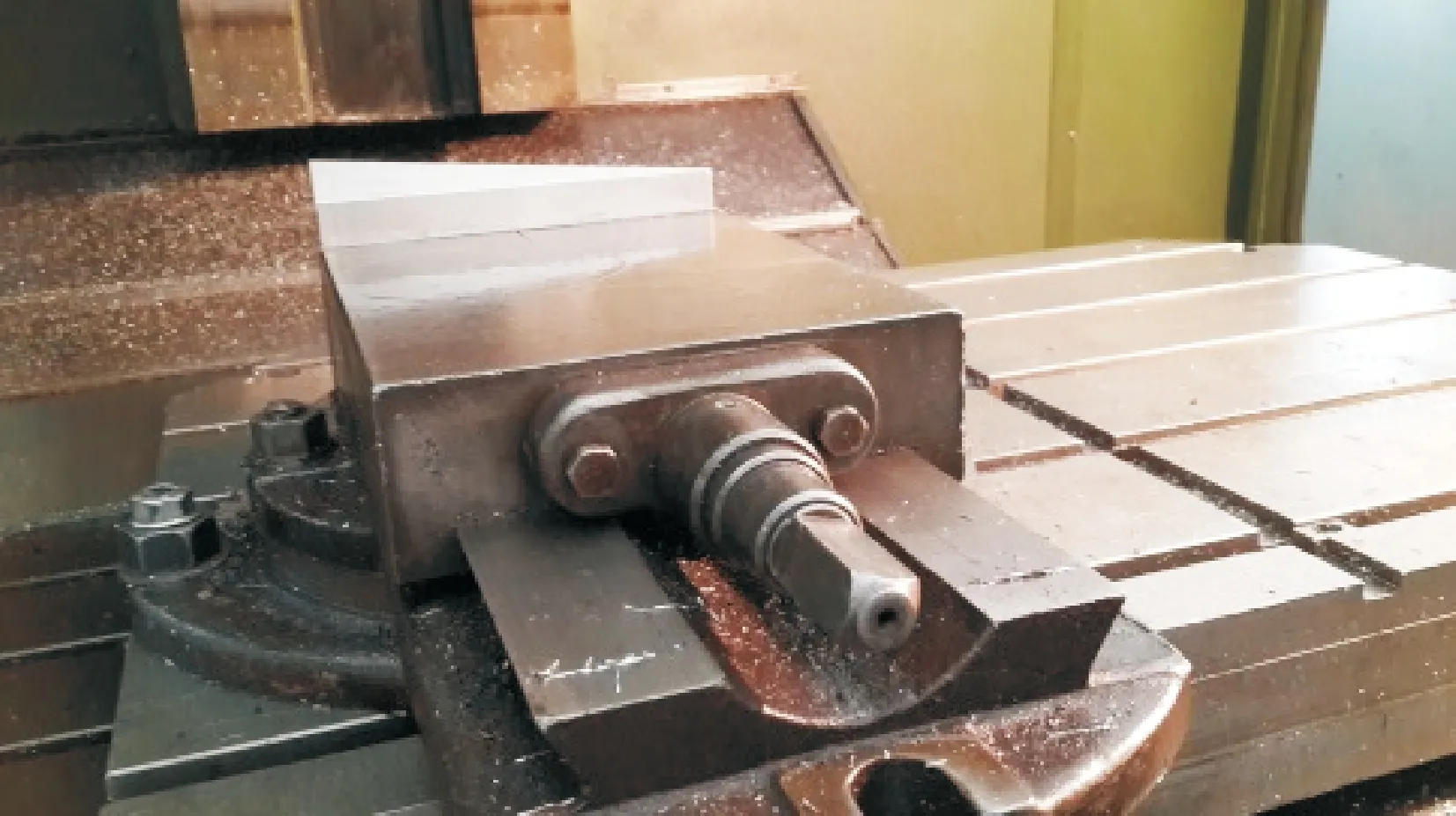
Fig.7 Experimental setup
(1) Helix angle
To verify the effect of helix angle on stability of thin walled workpiece, test were performed with two end mill cutters of dia 12 mm with helix angles 30° and 45°(Fig.8). Tests were performed as listed in Table 3 along with surface roughness measurement made along the length of cut at two points 140 mm and 180 mm. Measurement was taken three times at a point and their mean was obtained. For each test RDOC was 1 mm and feed of 0.15 mm/tooth was used to maintain the constant chip load.
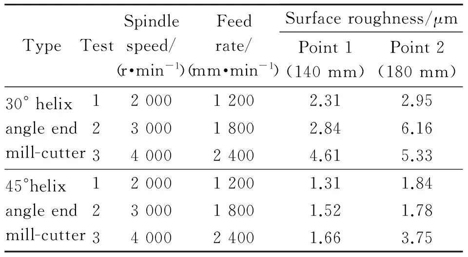
Table 3 Test parameters Ⅰ
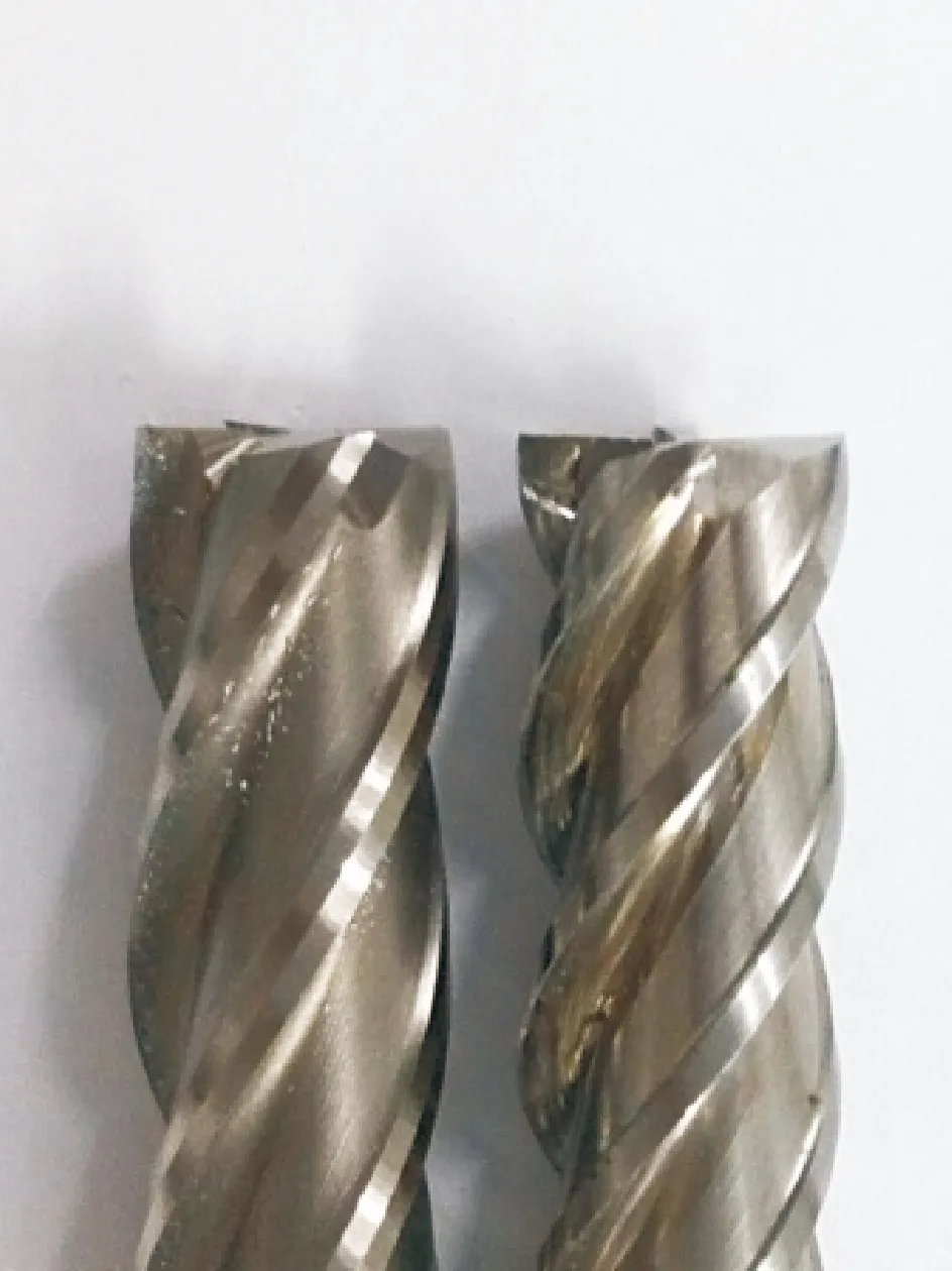
Fig.8 End mill cutter (helix angle)
(2) Number of flutes
In order to verify the effect of number of flutes of end mill cutter on stability of thin walled workpiece, test were performed with two 3-fluted and 4-fluted end mill cutters of dia 12 mm with helix angle 30° (Fig.9). Tests were performed as listed in Table 4 along with surface roughness measurement made along the length of cut at two points 140 mm and 180 mm. Measurement was taken three times at a point and their mean was obtained. For each test RDOC was 1 mm and feed of 0.15 mm/tooth was used to maintain the constant chip load.
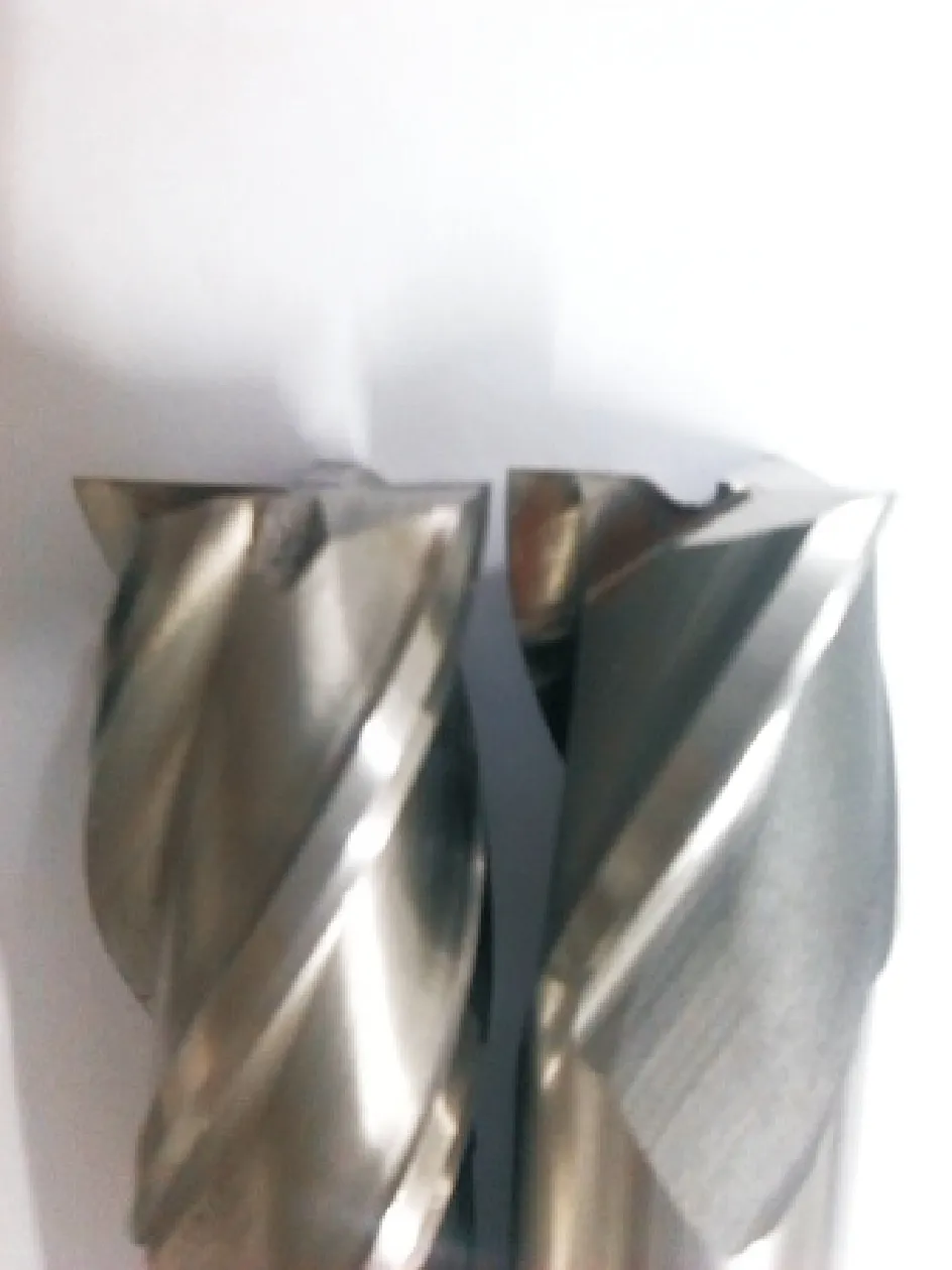
Fig.9 End mill cutter (number of flutes)
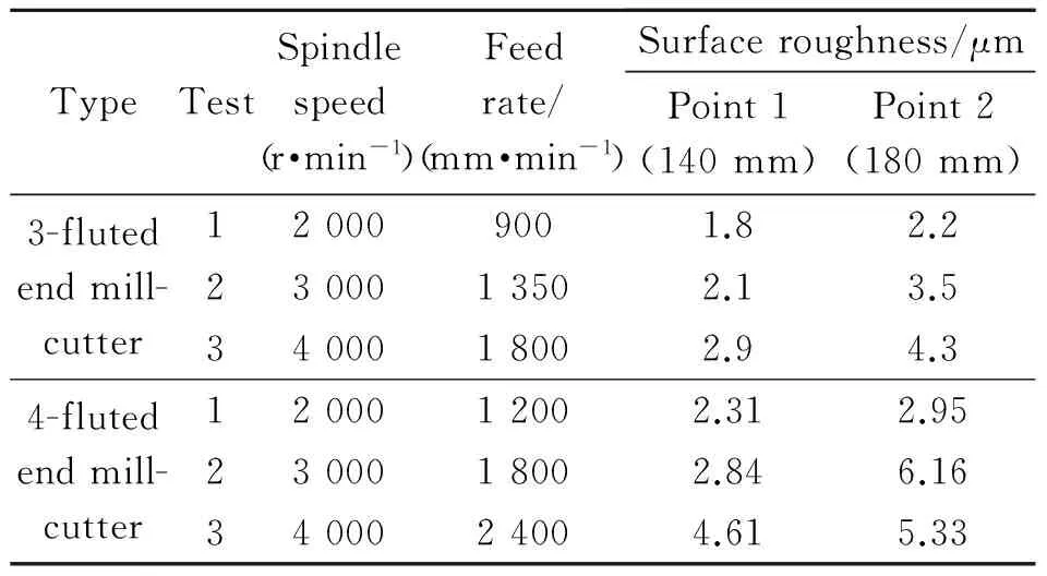
TypeTestSpindlespeed(r·min-1)Feedrate/(mm·min-1)Surfaceroughness/μmPoint1(140mm)Point2(180mm)3-flutedendmill-cutter120009001.82.22300013502.13.53400018002.94.34-flutedendmill-cutter1200012002.312.952300018002.846.163400024004.615.33
4 Conclusions
Chatter in machining is the most debilitating problem faced by modern machining industries, and its prediction, elimination and control becomes even more critical when the part to be machined is flexible. The present research presents an important contribution in the stability analysis of flexible parts milling by studying the influence of helix angle and number of flutes of milling cutter after contemplating an improved helix angle model in which very small changes in the initial and final immersion positions of the cutter arc segment are considered. The study concludes that
(1) A greater value of helix angle of the milling cutter improves the stability of the flexible parts milling and vice versa.
(2) The smaller the number of flutes, the more stable the milling of flexible parts, will be and vice versa.
[1] TAYLOR F W. On the art of cutting metals[M]. New York: Transactions of the American Society of Mechanical Engineers, 1907: 31-350.
[2] TLUSTY J, POLACEK M. The stability of machine tools against self excited vibrations in machining[J]. International Research in Production Engineering—American Society of Mechanical Engineers, 1963, I: 465-474.
[3] MERRITT H E. Theory of self-excited machine tool chatter[J]. Journal of Engineering for Industry, Transactions of the ASME, 1965, 87(4):447-454.
[4] SRIDHAR R, HOHN R E, LONG G W. A general formulation of the milling process equation[J]. Journal of Manufacturing Science and Engineering, 1968, 90(2): 317 - 324.
[5] GUILLEM Q, JOAQUIM C. Chatter in machining processes: A review[J]. International Journal of Machine Tools & Manufacture, 2011, 51(5): 363-376.
[6] BUDAK E, ALTINTAS Y. Analytical prediction of chatter stability in milling—Part I: General formulation[J]. Journal of Dynamic Systems, Measurement, and Control, 2011, 120(1): 22-30.
[7] BUDAK E, ALTINTAS Y. Analytical prediction of chatter stability in milling—Part Ⅱ: Application of the general formulation to common milling systems[J]. Journal of Dynamic Systems, Measurement, and Control, 2011, 120(1): 31-36.
[8] SEGUY S, CAMPA F J, LACALLE N L, et al. Toolpath dependent stability lobes for the milling of thin-walled parts[J]. International Journal of Machining and Machinability of Materials, 2008, 4(4): 377-392.
[9] THEVENOT V, ARNAUD L, DESSEI G, et al. Integration of dynamic behaviour variations in the stability lobes method: 3D lobes construction and application to thin walled structure milling[J]. International Journal of Advanced Manufacturing Technology, 2006, 27(7/8): 638-644.
[10]SONG Qinghua, WAN Yi, YU Shuiqing, et al. Stability prediction during thinwalled workpiece high-speed milling[J]. Advanced Materials Research, 2009, 69: 428-432.
[11]TANG Aijun, LIU Zhanqiang. Three-dimensional stability lobe and maximum material removal rate in end milling of thin-walled plate[J]. International Journal of Advanced Manufacturing Technology, 2009, 43(1/2): 33-39.
[12]DAVIES M A, BALACHANDRAN B. Impact dynamics in milling of thin-walled structures[J]. Nonlinear Dynamics, 2000, 22(4): 375-392.
[13]ADETORO O B, SIM W M, WEN P H. An improved prediction of stability lobes using nonlinear thin wall dynamics[J]. Journal of Materials Processing Technology, 2010, 210(6/7): 969-979.
[14]ZATARAIN M, MUNOA J, PEIGNE G, et al. Analysis of the influence of mill helix angle on chatter stability[J]. CIRP Annals—Manufacturing Technology, 2006, 55(1): 365-368.
[15]ZATARAIN M, BEDIAGA I, MUNOA J, et al. Analysis of directional factors in milling: Importance of multi-frequency calculation and of the inclusion of the effect of the helix angle[J]. International Journal of Machine Tools and Manufacture, 2010, 47(5/6/7/8): 535-542.
[16]SHIRASE K, ALTINTAS Y. Cutting force and dimensional surface error generation in peripheral milling with variable pitch helical end mills[J]. International Journal of Machine Tools and Manufacture, 1996, 36(5): 567-584.
[17]BUDAK E. An analytical design method for milling cutters with nonconstant pitch to increase stability, part I: Theory[J]. Journal of Manufacturing Science and Engineering, Transactions of the ASME, 2003, 125(1): 29-34.
[18]BUDAK E. An analytical design method for milling cutters with nonconstant pitch to increase stability, part 2: Application[J]. Journal of Manufacturing Science and Engineering, Transactions of the ASME, 2003, 125(1): 35-38.
[19]SIMS N D, MANN B, HUYANAN S. Analytical prediction of chatter stability for variable pitch and variable helix milling tools[J]. Journal of Sound and Vibration, 2008, 317(3/4/5): 664-686.
[20]TURNER S, MERDOL D, ALTINTAS Y, et al. Modelling of the stability of variable helix end mills[J]. International Journal of Machine Tools and Manufacture, 2007, 47(9): 1410-1416.
[21]YUSOFF A R, TURNER S, TAYLOR C M, et al. The role of tool geometry in process damped milling[J]. International Journal of Advanced Manufacturing Technology, 2010,50(9/10/11/12): 883-895.
[22]MASUD A M,HUANG X, CHEN W L, et al. Milling dynamics of flexible part with helix angle[J]. Procedia Engineering, 2011, 23: 792-798.
[23]ALTINTAS Y. Manufacturing automation-metal cutting mechanics, machine tool vibrations and CNC design[M]. Cambridge: Cambridge University Press, 2000: 1-382.
[24]MCCAULEY C J.Machinery's handbook[M]. 25th ed. New York: Industrial Press Inc, 1996: 1-2800.
Mr.Muhammad Masud Akhtar is a doctoral candidate in the College of Mechanical and Electrical Engineering, Nanjing University of Aeronautics and Astronautics. His research has focused on mechanics and dynamics of machining.
Prof.Huang Xiang has been working in the College of Mechanical and Electrical Engineering, Nanjing University of Aeronautics and Astronautics. His research is focused on aircraft digital assembly technology and equipment.
Prof.Chen Wenliang has been working in the College of Mechanical and Electrical Engineering, Nanjing University of Aeronautics and Astronautics. His research is focused on aircraft assembly technology.
(Executive Editor: Zhang Bei)
TH161 Document code: A Article ID: 1005-1120(2016)06-0714-07
*Corresponding author, E-mail address:cwlme@nuaa.edu.cn. How to cite this article: Muhammad Masud Akhtar, Huang Xiang, Chen Wenliang. Influence of helix angle on stability of milling flexible parts[J]. Trans. Nanjing Univ. Aero. Astro., 2016, 33(6):714-721. http://dx.doi.org/10.16356/j.1005-1120.2016.06.714
杂志排行
Transactions of Nanjing University of Aeronautics and Astronautics的其它文章
- A Sequential Adaptive Method for Enhancing DOA Tracking Performance
- A Directional Differential-Fed UWB Antenna with Stable Radiation Pattern
- Numerical Simulation of An Axial Flow Fan with Proper Aft Fins for Floating Wind Turbines Model Test
- Capacity Analysis on Distributed Antenna System with Imperfect CSI over Rayleigh Fading Channel
- Acknowledgement to Reviewers
- TRANSACTIONS OF NANJ ING UNIVERSITY OF AERONAUTICS AND ASTRONAUTICS
