Structural Parameter Analyses on Rotor Airloads with New Type Blade-Tip Based on CFD/CSD Coupling Method
2016-02-09,,
, ,
National Key Laboratory of Science and Technology on Rotorcraft Aeromechanics, Nanjing University of Aeronautics and Astronautics, Nanjing 210016, P.R. China
Structural Parameter Analyses on Rotor Airloads with New Type Blade-Tip Based on CFD/CSD Coupling Method
WangJunyi,ZhaoQijun*,MaLi
National Key Laboratory of Science and Technology on Rotorcraft Aeromechanics, Nanjing University of Aeronautics and Astronautics, Nanjing 210016, P.R. China
(Received 15 October 2015; revised 17 March 2016; accepted 5 April 2016)
For accurate aeroelastic analysis, the unsteady rotor flowfield is solved by computational fluid dynamics (CFD) module based on RANS/Euler equations and moving-embedded grid system, while computational structural dynamics (CSD) module is introduced to handle blade flexibility. In CFD module, dual time-stepping algorithm is employed in temporal discretization, Jameson two-order central difference (JST) scheme is adopted in spatial discretization and B-L turbulent model is used to illustrate the viscous effect. The CSD module is developed based on Hamilton′s variational principles and moderate deflection beam theory. Grid deformation is implemented using algebraic method through coordinate transformations to achieve deflections with high quality and efficiency. A CFD/CSD loose coupling strategy is developed to transfer information between rotor flowfield and blade structure. The CFD and the CSD modules are verified seperately. Then the CFD/CSD loose coupling is adopted in airloads prediction of UH-60A rotor under high speed forward flight condition. The calculated results agree well with test data. Finally, effects of torsional stiffness properties on airloads of rotors with different tip swept angles (from 10° forward to 30° backward) are investigated. The results are evaluated through pressure distribution and airloads variation, and some meaningful conclusions are drawn the moderated shock wave strength and pressure gradient caused by varied tip swept angle and structural properties.
rotor; airloads; structural parameter; computational fluid dynamics (CFD); computational structural dynamics (CSD); loose coupling method
0 Introduction
In order to obtain accurate rotor airloads, the unsteady, three-dimensional flowfield details around the rotor are required[1], but the lifting line aerodynamic method used in the computational structure dynamics (CSD) module lacks accuracy compared to high-fidelity computational fluid dynamics (CFD) method; rotor blades are highly flexible; and structural deformations have significant influences on rotor aerodynamic characteristics. Therefore, CFD and CSD codes mutually depend on each other in rotor unsteady airloads prediction. Furthermore, advanced blade-tip shapes, such as swept and anhedral, are widely employed in modern helicopter rotor design to acquire better aerodynamic performance[2]. This unconventional rotor blade design increases the difficulty in aerodynamic characteristic analyses and enables CFD/CSD coupling strategy to be a necessary tool for high-fidelity airloads prediction as well as dynamics analysis.
Furthermore, the elastic deformations of rotor in forward flight can be modified through varying structural property distribution in spanwise direction. Through such a parametric investigation on these properties, the relationship between structural properties and aeroelastic loads can be understood and the preferred structural property configuration may be obtained for better dynamics characteristics.
In 1986, Tung and Caradonna et al.[3]carried out CFD/CSD coupling for the first time and coupled the transonic small-disturbance code with comprehensive code CAMRAD to analyze lifting rotor in forward flight. In 2006, Potsdam et al.[4]studied the UH-60A airloads under different conditions using loosely coupled OVERFLOW-D and CAMRAD II and obtained better results over the lifting line aerodynamics used in CSD. Nygaard et al.[5]coupled OVERFLOW-2 with RCAS to investigate the parameter sensitivity of loose coupling in calculating unsteady airloads of rotor in forward flight, and then studied rotor unsteady airloads in the transient maneuver flight using tight coupling. In 2011, Yeo et al.[6]analyzed the aeroelastic stability of ADM rotor by adopting tight CFD/CSD coupling strategy, and the OVERFLOW-2/RCAS coupling method captured better key features in the damping trends of rotor. In 2011, Ahmad et al.[7]coupled OVERFLOW and CAMRAD-II to conduct flowfield simulation with high-fidelity and investigated the effect of coupling parameters such as iteration number and azimuth step size.
The parametric investigations of structural properties using CFD/CSD coupling method are not widely published, especially for rotors with advanced blade-tip shape. The subject of this paper is to investigate the UH-60A rotor flowfield in high speed forward flight using CFD/CSD loose coupling and carry out parametric study on both geometric and structural properties. Firstly, both CFD and CSD modules are verified through computing Helishape 7A rotor, Caradonna-Tung rotor and UH-60A rotor blade. Then the unsteady airloads and pressure distributions of UH-60A rotor are calculated and compared with available experimental data. Thereafter, parametric investigations on rotors with different blade-tip swept angles are conducted. Finally, parametric investigations on structural stiffness are accomplished by varying the structural properties of rotor blades with different tip swept angles.
1 Numerical Methodologies
1.1 CFD method
In the present work, C-H body-fitting blade grid is used in spatial discretization, as shown in Fig.1. The grid point number is 149×84×31 (chordwise, spanwise, and normal) to capture the viscous flow in the vicinity of blade region.
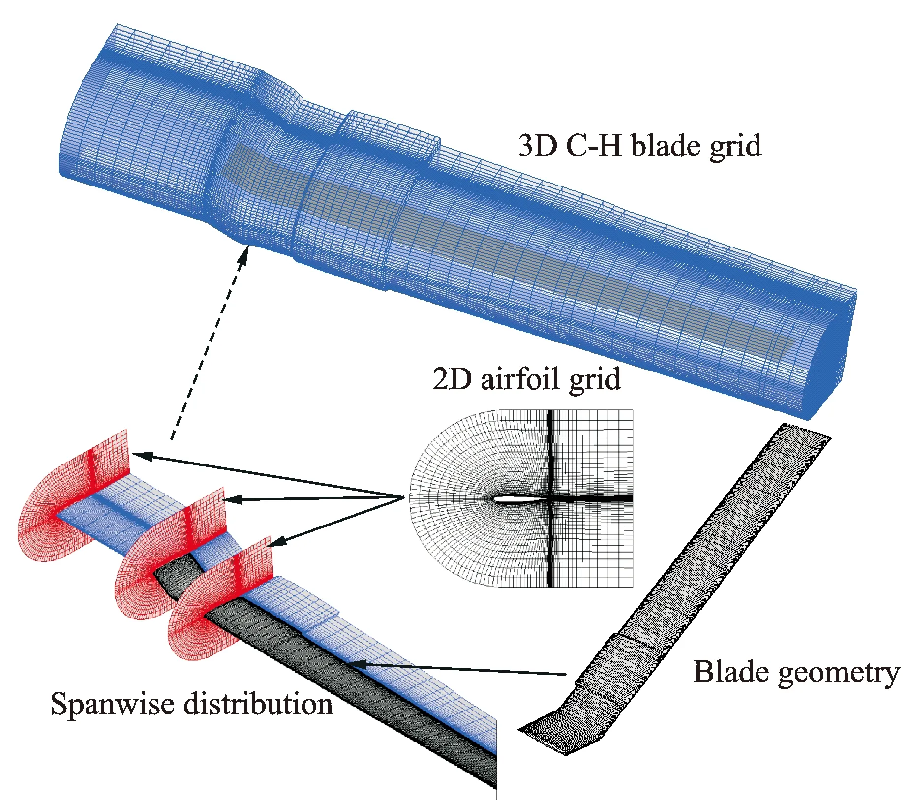
Fig.1 C-H body-fitting blade grid
Thereafter, the Cartesian background grid is generated around blade grid and extended into farfield. The dimension is 164×142×121 so that the overall grid number is about 5 million since 4 blade grids are used. The ″Top-Map″ hole cutting method is adopted to determine the spatial relationship between the body-fitting deformable grid and the Cartesian background grid, and the moving-embedded grid system is shown in Fig.2 with the donor elements searched by adopting ″Inverse Map″ method.
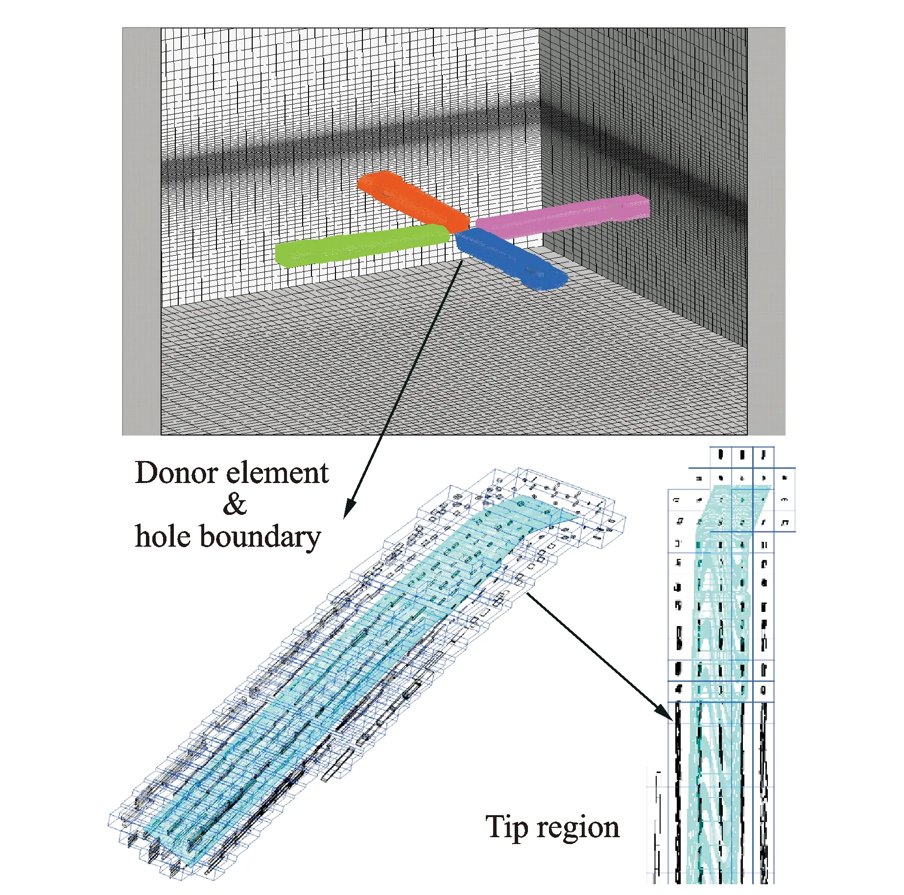
Fig.2 Moving-embedded grid of helicopter rotor
The blade deformation is carried out based on the algebraic method. The six degrees of freedom motion of rotor blade are defined by three translations and three rotation deflections of blade quarter line, while the airfoil cross sections maintain the original shape. As inheriting the algebraic nature of the C-H blade grid, this method of grid deformation is efficient with good quality.
The flowfield solver is developed based on RANS and Euler equations for blade body-fitting grids and Cartesian background grid, respectively. The RANS governing equations in conservative form are[8]
(1)
whereWis the conservative variables,Fcthe convective flux andFvthe viscous flux. The equations are calculated using JST scheme in spatial discretization. Dual time-stepping algorithm is adopted to simulate the unsteady flowfield, and 4-stage Runge-Kutta scheme is employed. The viscous region around the rotor is calculated by using B-L turbulence model. The farfield boundary condition is determined according to Riemann invariant while the inner boundary is no-slip condition for RANS equations. Euler equations are only used in background region to compromise between accuracy and efficiency.
1.2 CSD method
The CSD module is developed based on Hamilton′s variational principle[9]
(2)

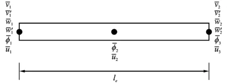
Fig.3 DOFs of beam element
In order to improve the accuracy of dynamics prediction for rotors with advanced blade tips, multiple beam elements are used for blade-tip modeling[10]. The modified tip beam element could be expressed as
(3)

The discrete equations of motion (Eq.4) for each element are assembled to form the blade equations of motion. These equations are then solved by using Newmark-Beta method to obtain the blade structural deflection affected by aerodynamic forces, which can either come from lifting-line theory or computational fluid dynamics solver
(4)
where [Mi],[Ci], [Ki],Fiare the element mass, the damping, the stiffness matrix and the force vector, respectively.
When lifting-line theory is used to carry out aeroelastic analysis, both linear inflow model and quasi-static aerodynamic model are activated.
1.3 Coupling strategy
After the CFD and the CSD modules are established, coupling strategy is required to transfer rotor flowfield and blade structure information between the two modules. In this paper, loose coupling (LC) is carried out in rotor airloads prediction according to level steady flight conditions[11], and the flowchart of LC is shown in Fig.4. Firstly, the moving-embedded grid system is introduced. Then, initial blade deflections are calculated by using the CSD module combining with lifting-line aerodynamics. Thereafter, loose coupling is carried out, starting from the CFD module to obtain the flowfield distribution and aerodynamic loads of deformed rotor blades. When the airloads over a revolution are computed, the information is transferred to the CSD module to update the deformation for the next revolution.

Fig.4 Flowchart of CFD/CSD loose coupling strategy
2 Modular Validation
Two modules adopted in CFD/CSD coupling are required to be verified through isolated calculation. In the present work, Helishape 7A and Caradonna-Tung rotor is taken as numerical example to validate the CFD module, while UH-60A blade is employed in CSD validation.
2.1 CFD module
In order to eliminate the effect of blade elasticity, rigid rotor is required to validate the CFD module. Helishape 7A rotor in hover[12]and Caradonna-Tung rotor in forward flight[13]are relatively rigid, and the computed pressure distributions at different spanwise positions and azimuth angles are shown in Fig.5, wherer/Ris the position of airfoil section,Cpthe pressure coefficient andφthe azimuthal angle . The calculated pressure coefficient distributions agree well with the experimental data, which proves the effectiveness of the CFD module developed in both hover and forward flight condition.
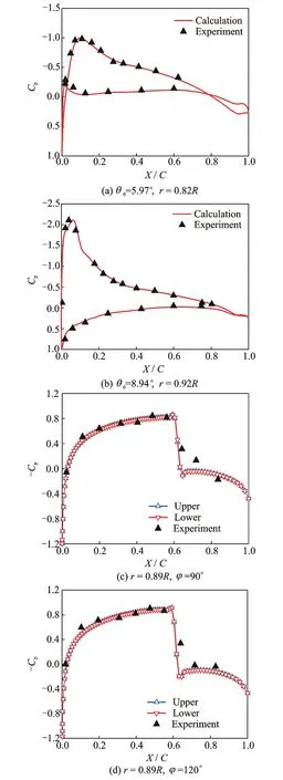
Fig.5 Pressure distribution of Helishape 7A and Caradonna-Tung rotor
2.2 CSD module
The CSD module is validated through analyzing the natural frequency of UH-60A rotor[14], as shown in Table 1. The reference results are calculated using UMARC software[15], and the discrepancies between the calculated and the reference results are minor, which indicates that the present CSD module can accurately represent the actual structural characteristics and could be used in CFD/CSD coupling analysis.
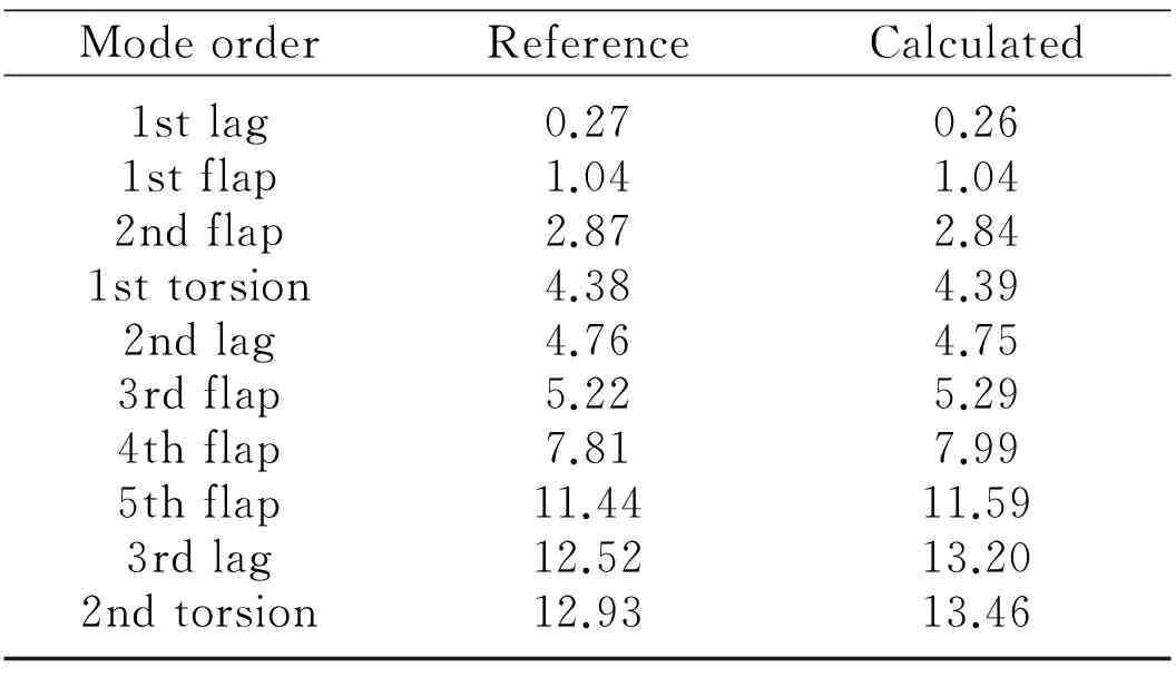
Table 1 Comparison of UH-60A natural frequency
Fig.6 shows the comparison of resonance diagram between calculated results with UMARC software calculations[16], Good agreement could be found and only minor difference exists in the low speed range.
F,LandTare the flap ,the lag and the torsion frequency, respectively, andΩ/Ω0is the rotor speed .
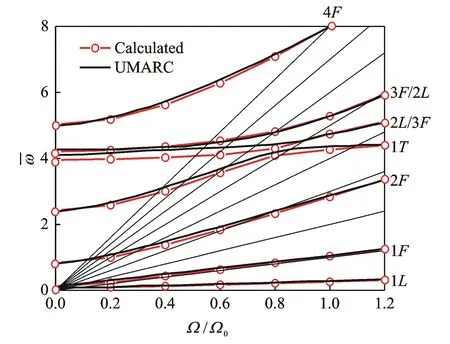
Fig.6 Resonance diagram of UH-60A rotor blade
3 CFD/CSD Coupling Results
3.1 Baseline UH-60A rotor
In the present work, UH-60A rotor in high speed forward flight is chosen to be the baseline analysis scenario, where the advance ratio is 0.368 and blade-tip Mach number is 0.642 (Case 8534). Firstly, the airloads of UH-60A rotor blade at different spanwise positions in a revolution is computed using CFD/CSD coupling method and the calculated normal forces are shown in Fig.7. The magnitude and the phase of the calcu-lated loads M2Cn agree well with the test data[17], and the perturbation of the airloads in a revolution is also captured well.
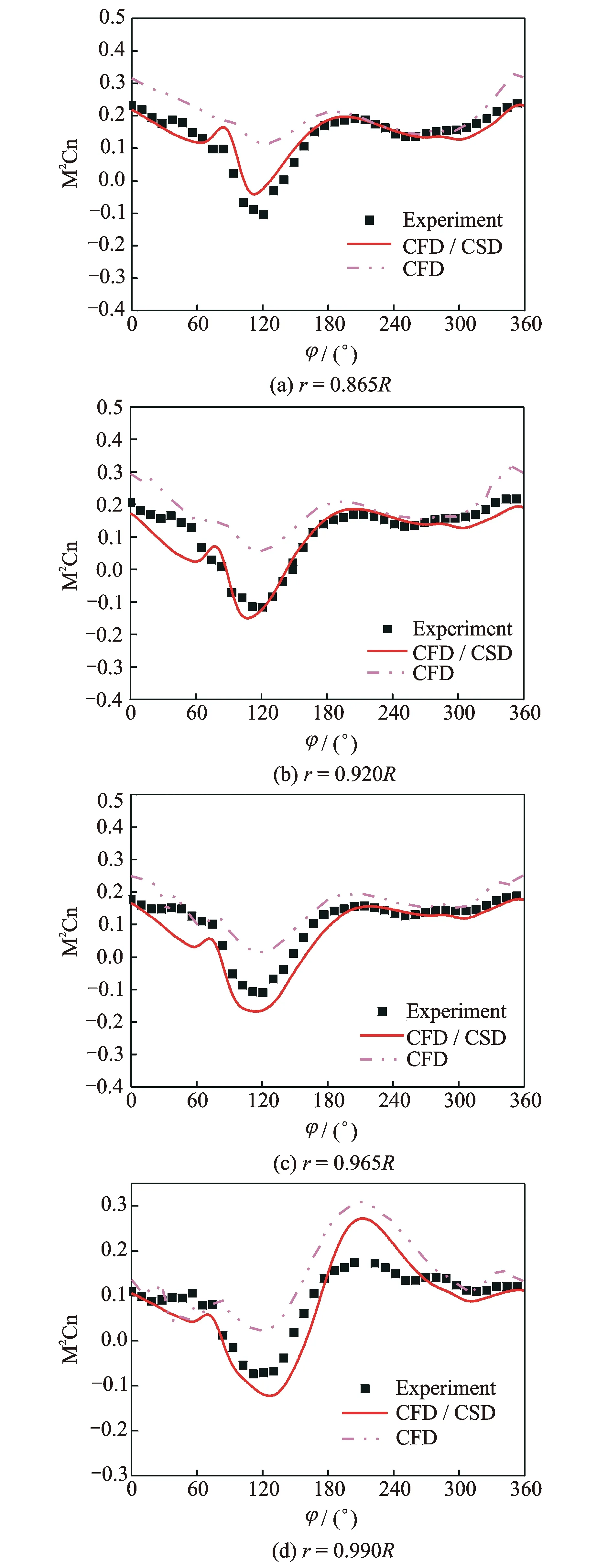
Fig.7 Normal force coefficient distributions of UH-60A rotor blade
In Fig.8, the calculated pressure coefficient distributions of UH-60A rotor in C8534 are compared with experimental data[18]. Both the magnitude and the position of shock wave agree well, which indicates the effectiveness of the present CFD/CSD analysis in the unsteady flowfield of elastic rotor.
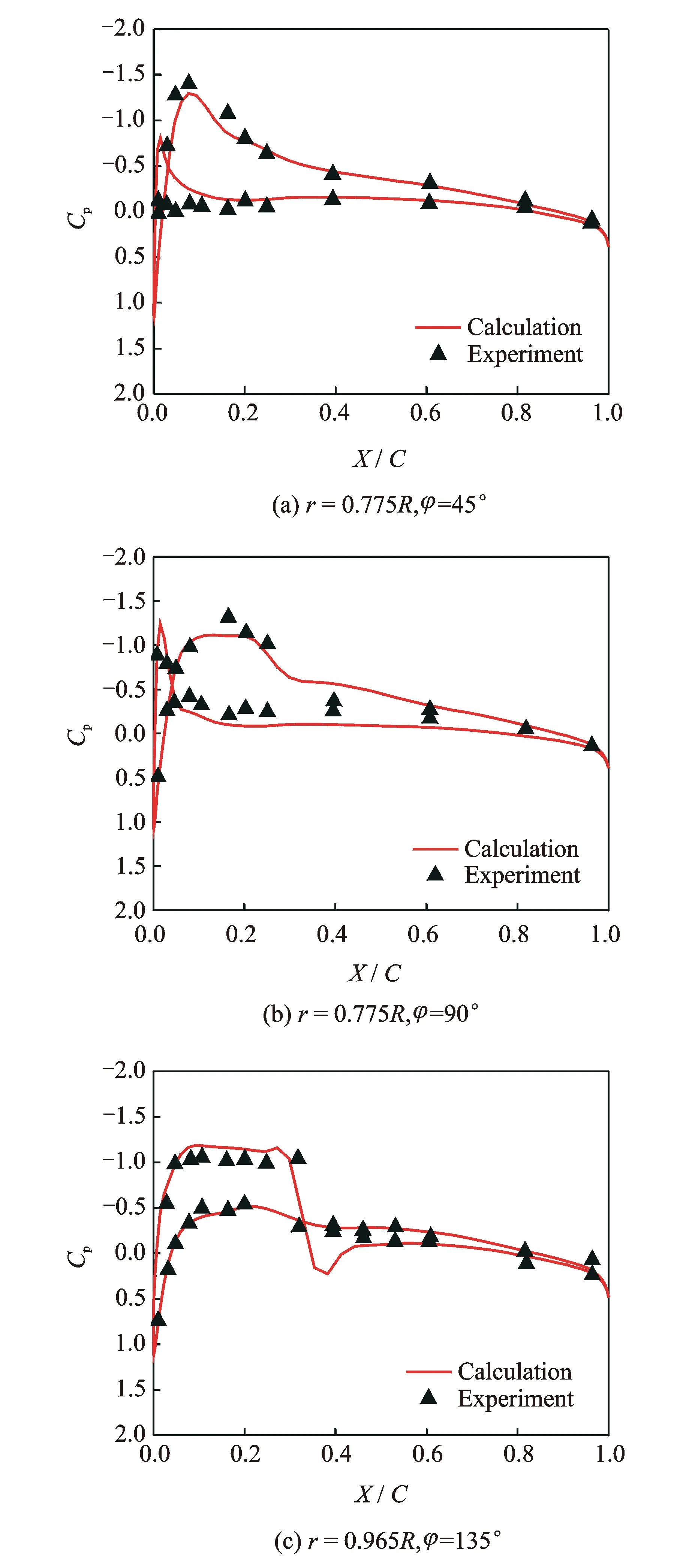
Fig.8 Pressure coefficient distributions of UH-60A rotor blade
3.2 Structural properties
To investigate the aerodynamic characteristics of rotor with different structural properties, the torsional stiffness of UH-60A rotor blades are varied from 160% to 40% of the original value, and it is assumed that no structural instability will emerge in this range. In the present analysis, TP60 means torsional stiffness plus 60% while TM60 means minus 60%. For different tip swept angles, SFT1 means swept forward tip of 10° and SBT0, SBT1, SBT2 and SBT3 represent swept backward tip of 0°, 10°, 20° and 30°, respectively. Elastic rotor blades with different tip swept angle are investigated for better understanding on combined effects of blade tip and structural parameters.
Firstly, normal force variations in a revolution are compared for blades with different swept angles and structural stiffness (Fig.9). The original lines represent airloads calculated based on the original UH-60A rotor sectional properties. For different tip swept angles, the differences in normal forces appear in the advancing side and only minor discrepancies are found on the retreating side. This might be caused by the strong shock in the advancing side, especially between 60° to 120° azimuth angle, and softer blade will generate more severe lift peak as the result of larger structural deflection affected by the aerodynamic forces. This trend increases with the increase of tip swept angle, which may be caused by the increased distance of aerodynamic forces center from the feathering line.
Then, the pressure coefficient distributions are compared for rotor blades with different structural stiffness, as shown in Fig.10. It could be seen from the comparisons that blade with smaller torsional stiffness would generate smaller lift due to the pressure differences on blade surface, which indicates the reduced structural properties may benefit the reasonable pressure distribution at the advancing side.
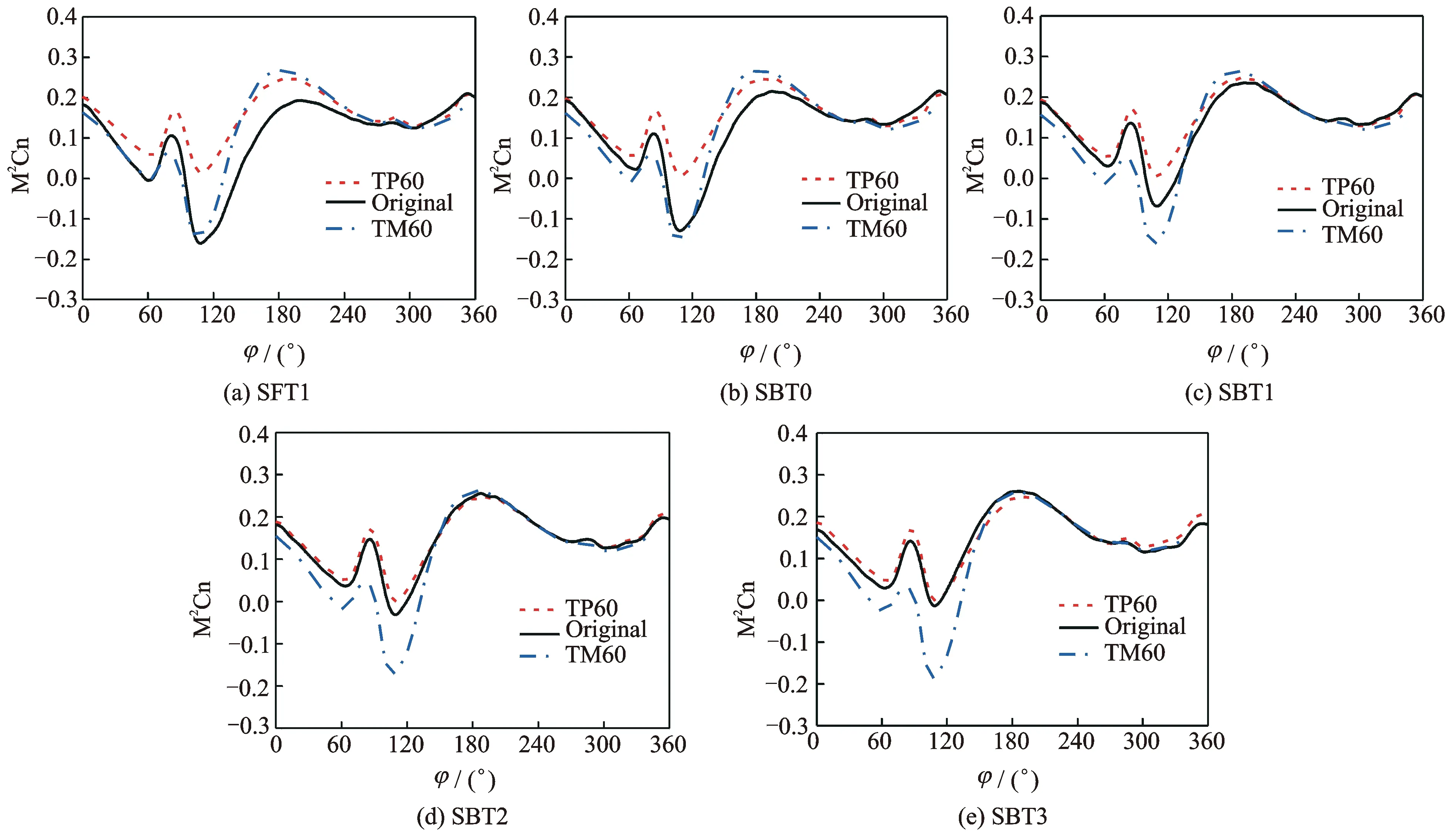
Fig.9 Normal force coefficient distributions of UH-60A blade at 0.865R with different torsional stiffness
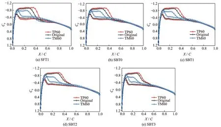
Fig.10 Pressure coefficient distributions of UH-60A rotor blade at 0.865R and 90° azimuth angle
The calculated pressure distributions on the upper surface of blade with different structural properties are shown in Fig.11. The top blade has the largest torsional stiffness while blade with the least stiffness is at the bottom, and the properties of the seven blades from top to bottom are TP60, TP30, TP15, original, TM15, TM30 and TM60, respectively. The legend on the right hand side is also pressure in Pascal. It can be seen from these figures that reduced structural stiffness could significantly decimate the strength of shock waves as the result of magnified torsional deformation. Forward swept tip could reduce the pressure gradient in vicinity of blade tip while relatively strong shock is observed at the corner, which is similar to the rigid rotor case. Backward swept tip could also reduce the considerable pressure gradient at the advancing side, and this effect will be magnified with larger tip swept angle. Softer blade could moderate the pressure distribution on blades with different swept angles.
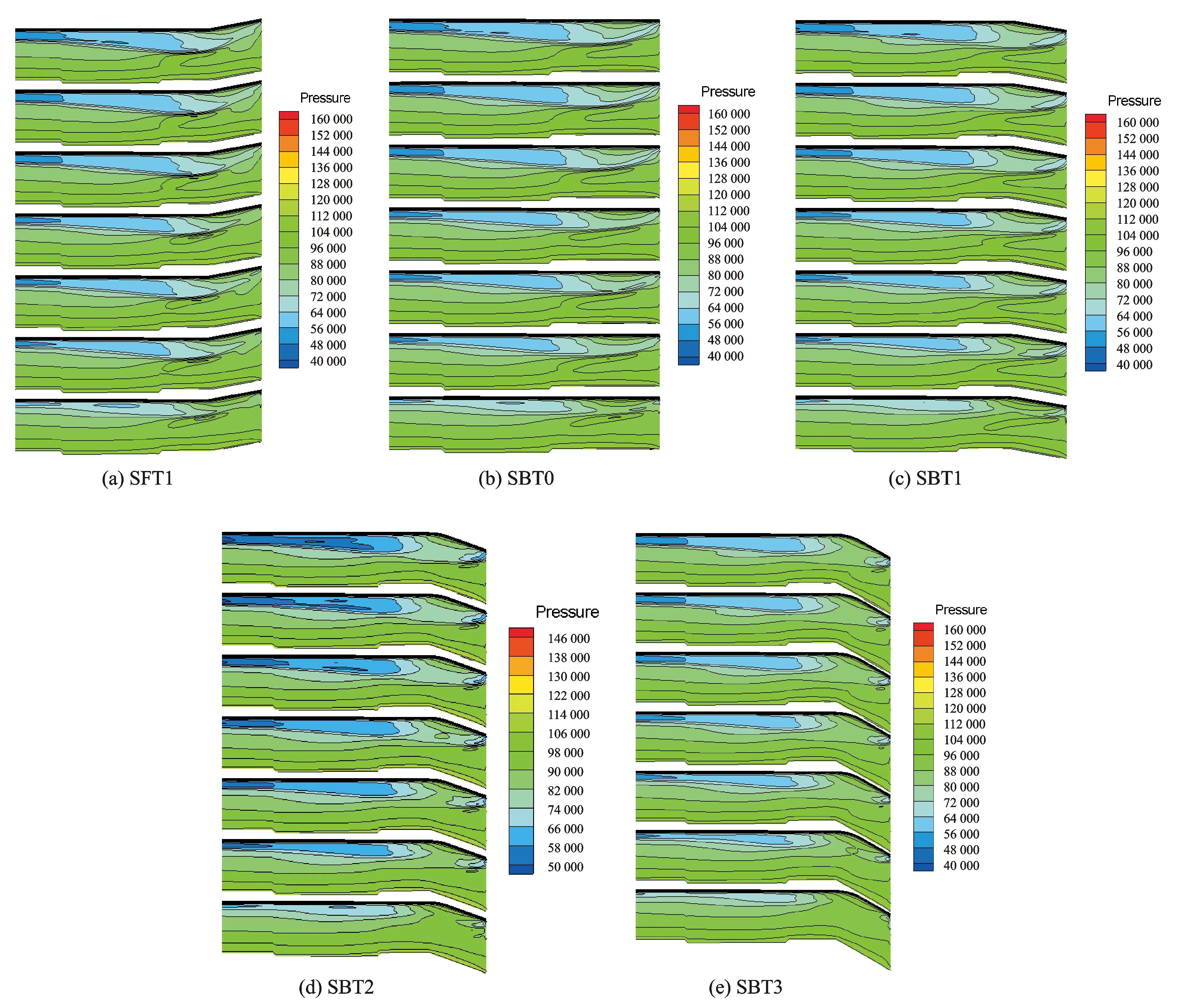
Fig.11 Pressure distributions of UH-60A rotor blade at tip region with different structural stiffness
4 Conclusions
A RANS/Euler CFD solver has been loosely coupled with a CSD solver based on moderate deformation beam theory. The unsteady flowfield and aerodynamic airloads of UH-60A rotor are simulated by using the developed method. Parametric investigations on the effects of structural properties with variations of tip swept angle are carried out. The following conclusions are obtained:
(1) The CFD/CSD coupling method established in the present work is able to simulate the unsteady flowfield and aerodynamic airloads as well as the natural frequency of rotor with advanced blade-tip shape and different structural stiffness in forward flight.
(2) Reduced structural stiffness could significantly decimate the strength of shock waves and moderate the pressure distribution on blades with different swept angles.
(3) Better aerodynamics characteristics could be obtained through varying geometric and structural properties, which could be beneficial to further investigation of aerodynamic optimization using CFD/CSD method.
[1] DATTA A, CHOPRA I. Prediction of the UH-60A main rotor structural loads using computational fluid dynamics/comprehensive analysis coupling[J]. Journal of the American Helicopter Society, 2008,53 (4): 351-365.
[2] BROCKLEHURST A, BARAKOS G N. A review of helicopter rotor blade tip shapes[J]. Progress in Aerospace Sciences, 2013,56(3):35-74.
[3] TUNG C, CARADONNA F X, JOHNSON W. The prediction of transonic flows on an advancing rotor[J]. Journal of the American Helicopter Society, 1986, 32(3):4-9.
[4] POTSDAM M, YEO H, JOHNSON W. Rotor airloads prediction using loose aerodynamic/structural coupling[J]. Journal of Aircraft, 2006, 43(3): 732-742.
[5] NYGAARD T A, SABERI H, ORMISTON R A, et al. CFD and CSD coupling algorithms and fluid structure interface for rotorcraft aeromechanics in steady and transient flight condition[C]// American Helicopter Society 62nd Annual Forum Proceedings. Phoenix, AZ: [s.n.], 2006:1772.
[6] YEO H, POTSDAM M, ORMISTON R A. Rotor aeroelastic stability analysis using coupled computational fluid dynamics/computational structure dynamics[J]. Journal of the American Helicopter Society, 2011,56(4):1-16.
[7] AHMAD J U. CHADERJIAN N M. High-order accurate CFD/CSB simulation of the uh-60 rotor in forward flight [C]// 29th AIAA Applied Aerodynamics Conference Proceedings, Honolulu, HI: AIAA, 2011.
[8] BLAZEK J. Computational fluid dynamics: Principles and applications[M]. Second Edition. New York: Elsevier Ltd, 2005.
[9] YUAN K A, FRIEDMANN P P. Aeroelasticity and structural optimization of composite helicopter rotor blades with swept tips[R]. NASA CR-4665, 1995.
[10]PANDA B. Assembly of moderate-rotation finite elements used in helicopter rotor dynamics[J]. Journal of the American Helicopter Society, 1987,32(4):63-69.
[11]JOHNSON W. Milestones in rotorcraft aeromechanics Alexander A. Nikolsky honorary lecture[J]. Journal of the American Helicopter Society, 2011,56(3):1-24.
[12]HOPKINS A S, ORMISTON R A. An examination of selected problems in rotor blade structural mechanics and dynamics[J]. Journal of the American Helicopter Society, 2006,51(1):104-119.
[13]CARADONNA F X, LAUB G H, TUNG C. An experimental investigation of the parallel blade-vortex interactional[R]. NASA TM-86005, 1984.
[14]DAVIS S J. Predesign study for a modern 4-bladed rotor for the RSRA[R]. NASA CR 166155, 1981.
[15]ABHISHEK A, DATTA A, CHOPRA I. Prediction of UH-60A structural loads using multibody analysis and swashplate dynamics[J]. Journal of Aircraft, 2009,46(2):474-490.
[16]DATTA A, SITARAMAN J, CHOPRA I, et al. CFD/CSD prediction of rotor vibratory loads in high-speed flight[J]. Journal of Aircraft, 2006,43(6):1698-1709.
[17]SITARAMAN J, BAEDER J, CHOPRA I. Validation of UH-60A rotor blade aerodynamic characteristics using CFD[C]//American Helicopter Society 59th Annual Forum Proceedings. Phoenix, AZ:[s.n.], 2003:1452-1468.
[18]LORBER P F. Aerodynamic results of a pressure-instrumented model rotor test at the DNW [J]. Journal of the American Helicopter Society, 1991,36(4):66-76.
Mr. Wang Junyi is a postgraduate student in Nanjing University of Aeronautics and Astronautics (NUAA).His research has focused on helicopter aerodynamics and rotor CFD/CSD coupling method.
Prof. Zhao Qijun is a professor and Ph.D. advisor at the College of Aerospace Engineering, Nanjing University of Aeronautics and Astronautics, where he received his Ph.D. degree in aircraft design. His main research interests are helicopter CFD, helicopter aerodynamics, aerodynamic shape design of toor blade, active flow control of rotor, and rotor aeroacoustics.
Mr. Ma Li is a doctor candidate at NUAA. His research has focused on helicopter aerodynamics and rotor CFD/CSD coupling method.
(Executive Editor: Zhang Bei)
V211.47 Document code:A Article ID:1005-1120(2016)06-0678-09
*Corresponding author, E-mail address: zhaoqijun@nuaa.edu.cn. How to cite this article: Wang Junyi, Zhao Qijun, Ma Li. Structural parameter analyses on rotor airloads with new type blade-tip based on CFD/CSD coupling method[J]. Trans. Nanjing Univ. Aero. Astro., 2016,33(6):678-686. http://dx.doi.org/10.16356/j.1005-1120.2016.06.678
杂志排行
Transactions of Nanjing University of Aeronautics and Astronautics的其它文章
- A Sequential Adaptive Method for Enhancing DOA Tracking Performance
- A Directional Differential-Fed UWB Antenna with Stable Radiation Pattern
- Numerical Simulation of An Axial Flow Fan with Proper Aft Fins for Floating Wind Turbines Model Test
- Capacity Analysis on Distributed Antenna System with Imperfect CSI over Rayleigh Fading Channel
- Acknowledgement to Reviewers
- TRANSACTIONS OF NANJ ING UNIVERSITY OF AERONAUTICS AND ASTRONAUTICS
