Review on Key Techniques of Dynamics Modeling for Helicopter Simulator
2016-02-09,,
, ,
Research Center of Flight Simulation and Advanced Engineering Training, College of Civil Aviation,Nanjing University of Aeronautics and Astronautics, Nanjing 210016, P. R. China
Review on Key Techniques of Dynamics Modeling for Helicopter Simulator
GuHongbin*,FuJun,HuJinshuo
Research Center of Flight Simulation and Advanced Engineering Training, College of Civil Aviation,Nanjing University of Aeronautics and Astronautics, Nanjing 210016, P. R. China
(Received 22 August 2016; revised 16 November 2016; accepted 20 November 2016)
We review the state of the art of dynamic modeling methods for helicopter simulators. Major dynamic models, including ARMCOP, GENHEL, FLYRT, BEMAP, F-B412 and UTIAS, are introduced. We address off-axis response problem by focusing on flexible blade model, Pitt-Peters dynamic inflow model, Peters-He finite state inflow model and free wake model which are integrated with the baseline model. With the advances in computing power, efficient free-vortex algorithms and parallel processing, free wake model can be used to simulate in real-time and significantly improves the effectiveness of solving off-axis response problem.
helicopter; dynamic model; off-aixs response
0 Introduction
Flight simulators are indispensable tools for both training and researching. Fig.1 shows the train simulator developed by Sikorsky Aircraft Corporation[1], and Fig.2 the research simulator developed by The University of Liverpool[2]. In the effort of replicating complex flying maneuvers and conditions of the real aircraft, both the simulator mathematical model and the motion and visual systems are becoming increasingly sophisticated. A flight simulator cannot perfectly represent the aircraft in all aspects: The mathematical model of the aircraft has never been fully accurate, and the motion and visual systems have physical limitations that impede the full representation of the sensation of flying always toward perfection. Also, sophisticated simulator mathematical models are not convenient for obtaining physical insight into the mechanism of coupling between the different motion degrees of freedom.
Regulatory authorities have established standards for the acceptance and certification of simulators. For helicopters, the most widely recognized standard for simulation qualification is Federal Aviation Administration advisory circular AC 120-63[3], which is currently being reworked into joint-aviation-requirement (JAR) STD-1H[4]. The mathematical model (including sophisticated kinematics, structural, aerodynamic, and control dynamic aspects) is vital to flight simulators which must run in real-time. Flight simulator′s fidelity depends on mathematical model′s accuracy.
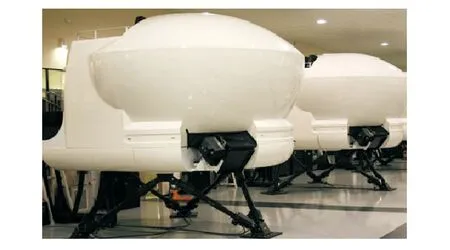
Fig.1 UH-60 level D train simulator
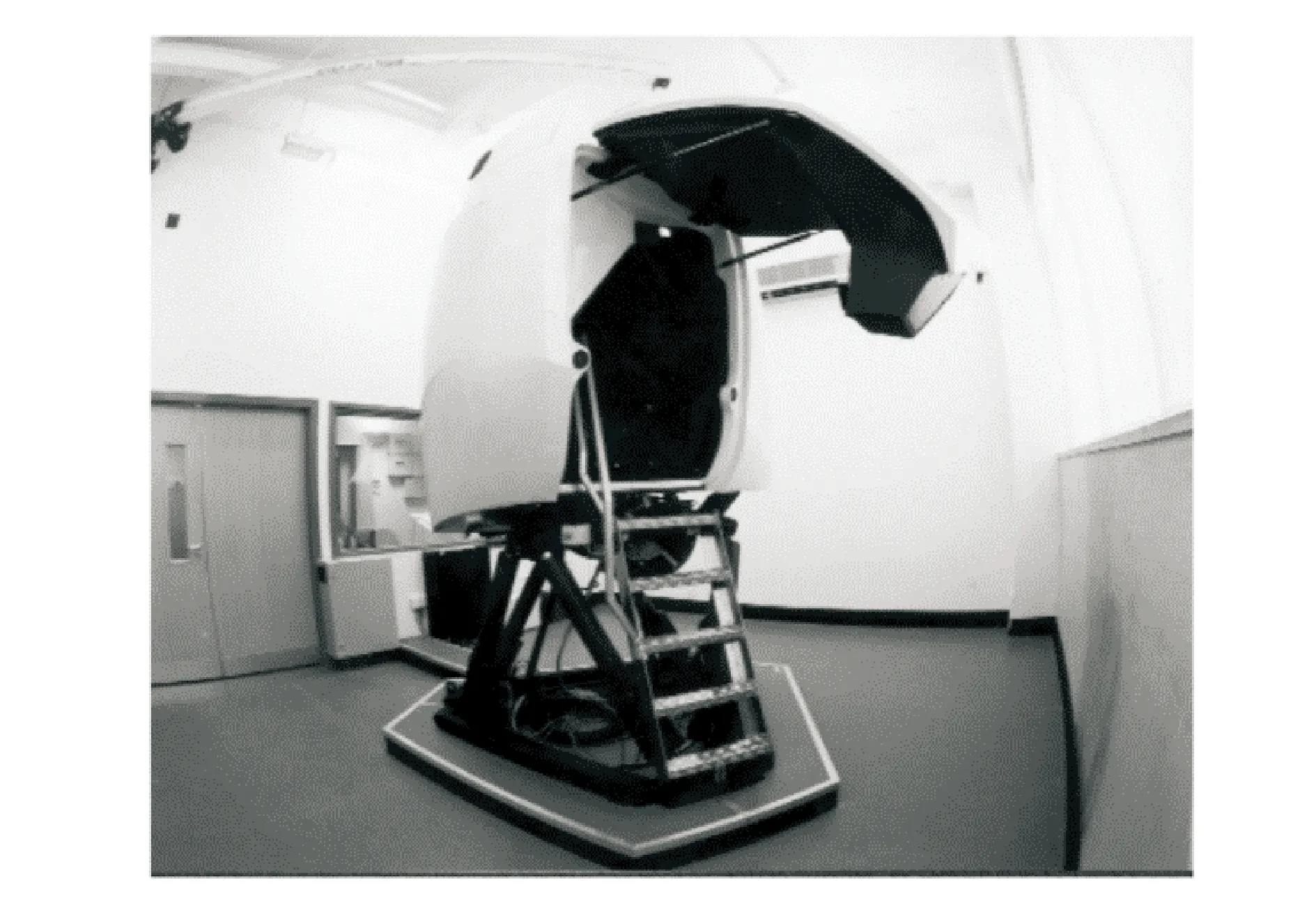
Fig.2 Research simulator at The University of Liverpool
We concentrate on mathematical model of dynamics, and overview dynamics modeling for the helicopter flight simulator.
1 Model Overview
In 1963, the equations of motion for a single-rotor helicopter were presented[5]. The aerodynamic equations were developed through a modified blade element approach, although other alternative techniques were considered. The equations were not constrained to one or a number of given flight conditions but valid for the entire flight regime including forward flight, hover, transition, autorotation, the effects of varying altitude, ground effects, and blade aeroelasticity in twist. They were suitable for analog, digital, and hybrid simulation programs. The equations included dynamic modeling of the main rotor and airframe to provide a mathematical model which will accept control inputs and calculate the resulting vehicle dynamics and orientation. The mathematical model for a single-rotor helicopter[5]was modified and implemented on the Langley Research Program Center real-time simulation (RTS) system[6]. The simulation program, with modifications by using a second-order Adams-Bashforth predictor integration formula with a solution rate of 32 iteration/s to solve the state variables and a modified secant method for trim condition calculation were used in support of two piloted studies of the Sikorsky S-61 helicopter, which was a five-blade, single-rotor, commercial passenger-type helicopter used by New York Airways. It was the early version of helicopter simulator, whose mathematical model was quietly simple when compared to further models.
ARMCOP model[7]is a mathematical model of a single main rotor helicopter for piloted simulation, which was developed by Ames Research Center. The model has ten degrees of freedom: Six rigid-body, three rotor-flapping, and rotor rotational degrees of freedom. The rotor model assumed rigid blades with rotor forces and moments radially integrated and summed about the azimuth. The fuselage aerodynamic model use a detailed representation over a nominal angle of attack and sideslip range of ±15°, and it used a simplified curve fit at large angles of attack or sideslip. Stabilizing surface aerodynamics were modeled with a lift curve slope between stall limits and a general curve fit for large angles of attack. A generalized stability and control for a simplified engine/governor model, atmospheric turbulence, and a linearized six-degree-of-freedom dynamic model for stability and control analysis. Then for a specific helicopter—UH-60, some revisions were conducted to the ARMCOP model, with the following objectives[8]: (1) Improvement of the fidelity of the UH-60 fuselage aerodynamic model over a wide range of angles of attack and sideslip angles; (2) Modification of the tail rotor aerodynamic model to include the option of canting the tail rotor and modeling its associated aerodynamic effects; (3) Incorporation in the model of the control system for the UH-60 horizontal stabilator with variable incidence and the resultant aerodynamic effects; (4) Incorporation of the UH-60′s pitch bias actuator as part of the stability and control augmentation system.
Sikorsky General Helicopter Flight Dynamics Simulation, known as GENHEL, provided the army with an engineering simulation for performance and handling quality evaluations. Initially, it was applied to analysis mode, which would eventually be used in the real time pilot-in-the-loop simulation. The model of BLACK HAWK helicopter was a total system, free flight representation based on GENHEL[9], and expanded/improved at Ames[10]. The basic model was a total force, non-linear, large angle representation in six rigid body degrees of freedom. The rotor aerodynamics were developed using a blade element approach. The total rotor forces and moments were developed from a combination of the aerodynamic, mass and inertia loads acting on each simulated blade. In the latter case, which represented the air mass degree of freedom, a uniform downwash was derived from momentum considerations, passed through a first order lag, and then distributed first harmonically as a function of rotor wake skew angle and the aerodynamic hub moment. The fuselage was defined by six component aerodynamic characteristics which were loaded from wind tunnel data which had been extended analytically to large angles. The aerodynamics of the empennage were treated separately from the forward airframe and used the look-up table method. The tail rotor was represented by the linearized closed form Bailey theory solution.
FLYRT model[11]is a model developed by the McDonnell Douglas Helicopter System′s Fly Real Time for the AH-64A. Unlike GENHEL model ,the FLYRT model used a map-type approach to model its main rotor. This modeling approach was originally conceived in the late 1970s′ to allow real-time operation with the limited computational capabilities available at that time[12]. The problem was that this technique complete depended on and was restricted by this pregenerated map, especially since the code for the generation of more maps was not provided as part of FLYRT. The restriction was deemed surmountable since the computational power of computers enabled the model to run blade-element models in real-time without the need for the generation of a map. A blade-element-type main-rotor module was therefore developed to replace the map-type module in FLYRT. The rotor module held the access to the actual physical parameters of the rotor, so as introduce corrections, enhancements, and new theories as they were developed. The new model was known as the Blade-Element Model for APache (BEMAP)[13]. The basic structure of the new rotor module is based on the main-rotor module of GENHEL. BEMAP was, therefore, a version of FLYRT which were: (1) Equipped with a blade-element main-rotor module; (2) Upgraded with new trim and modified Aquations-of-motion modules; (3) Restructured to improve modularity; (4) Enhanced with flight-data-control-input access capability for flight-data comparisons; and (5) Updated with a versatile plotting option.
F-B412 is the FLIGHTLAB simulation model of the Bell 412, developed by University of Liverpool[14], features a rigid, articulated, blade- element rotor formulation with flap and lag degrees of freedom. A quasi-steady aerodynamic component was used for the airload calculation on the blade elements. The blade was divided into several segments and each segment was treated as a two-dimensional panel producing aerodynamic loads as nonlinear functions of angle of attack, dynamic pressure and Mach number. The 2D aerofoil table should include lift, drag and pitch moment coefficients as functions of angle of attack and Mach number. There were several modelling options available within FLIGHTLAB for the fuselage aerodynamics, including a panel method and a simple table look-up. For the Bell-412 model, the table look-up option was chosen where the fuselage coefficients were supplied by means of look-up tables as functions of angle of attack and sideslip angle. Empennage aerodynamics tail rotor used the Bailey rotor model. The inflow model was the enhanced Peters-He finite state dynamic inflow model[15]. The F-B412 model produced very good on-axis responses in comparison to the NRC supplied flight test data over a broad speed range (15-120kt). However, off axis responses were mostly unsatisfactory[16].
The UTIAS helicopter models were loosely based on that in Ref.[9] combined with first principals derivations all programmed in The MathWorks′ Simulink®environment developed by University of Toronto[17-18]. The main rotor models employed a blade-element formulation, The model used the Pitt-Peters dynamic inflow model for determining the total airflow, augmented with dynamic wake distortion which could be disabled for comparisons. The rotor rotational speed was determined using a second-order engine dynamics model. The tail rotor loads were determined using a Bailey rotor model, which contained a number of assumptions such as uniform inflow and a linear lift curve. Aerodynamic forces and moments for the fuselage and empennage were determined using look-up tables. Table 1 represents the differences between several real-time helicopter dynamic models for flight simulators.
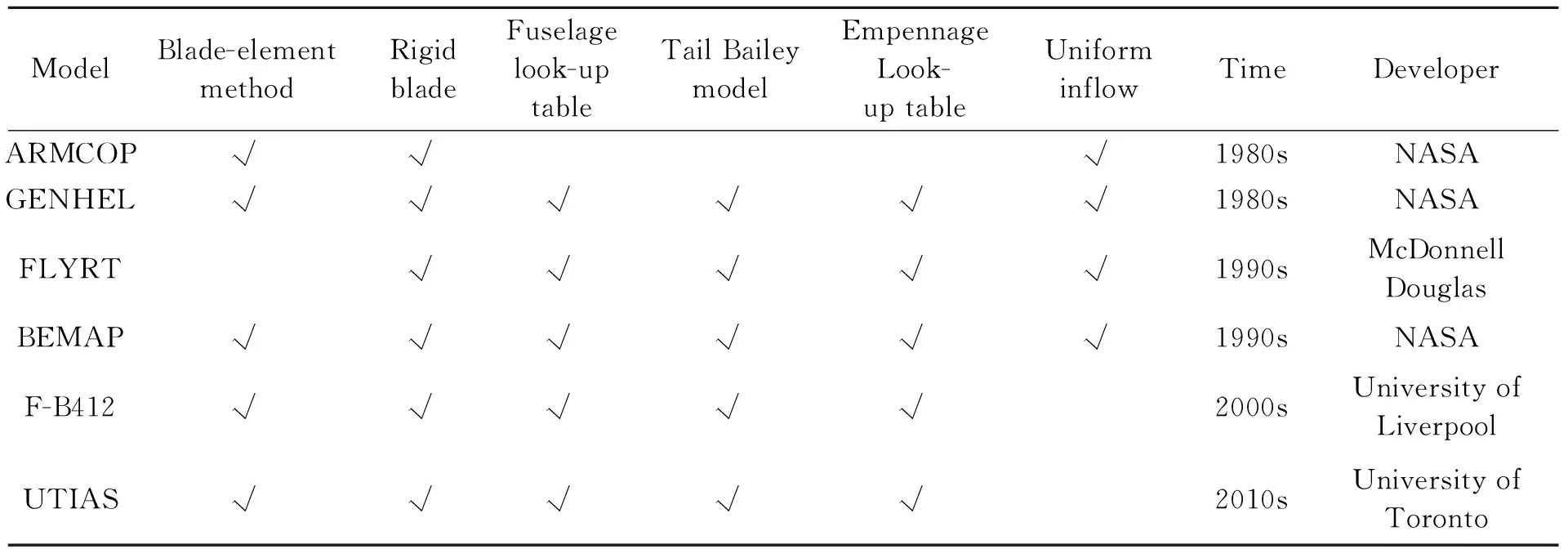
Table 1 Model comparison
In the early ages, the dynamic model was pure mathematical model representing helicopter′s characteristic. Then GENHEL model stood out as the first engineering model with the look-up table method for some component with flight test data and wind tunnel data. It notably has improved model′s fidelity. It has worked as the baseline model for many other simulator flight dynamic models, such as BEMAP, F-B412, UTIAS model, and also used in a low-cost engineering real-time simulation facility MDRSF at Penn State University[19]. Uniform inflow model in GENHEL tirst developed by Paul and Bernard[20], introduced a term representing the acceleration of a mass of air surrounding the rotor into momentum-disk-type model to explain observations of first-order dynamics of the induced velocity below a hovering rotor. With the advancement in rotor wake study, some new inflow models developed like Pitt-Peters dynamic inflow model[21-22], which used in UTIAS model, and Peters-He finite state dynamic inflow model,which used in F-B412 model. The F-B412 model has been used in HELIFLIGHT simulator at the University of Liverpool[2]. The UTIAS model has been used in UTIAS Flight Research Simulator at the University of Toronto[23]. Helicopter simulator is not only used in industry and commerce, but now also used by universities, who have endeavoured to establish their own research simulator for flight control design, advanced rotorcraft flight dynamics modeling and handling quality analysis.
2 Off-Axis Response Problem
An ongoing concern with helicopter simulations is that they often exhibit an incorrect off-axis response to cyclic control inputs when compared with the corresponding flight test data[24-29]. The off-axis response problem is that in a simulator the initial lateral response to a longitudinal cyclic input, and vice versa, notably differ from that observed in the actual aircraft, or even in opposite. To obtain good flying and handling qualities, the off-axis problem must be solved. In fact, FAA Level D rotorcraft flight simulator certification requires that the simulated off-axis response be similar to that of the real rotorcraft[3].
To understand this perplexing off-axis phenomena, there have been many attempts to explain the primary source of this problem. Most of the theories and methods can be classified as: (1)Flexible main rotor blades[17,30-44]; (2) Augmented Pitt-Peters dynamic inflow model and augmented Peters-He finite state inflow model[16,35-41]; (3) Free wake model[31,42-47].
2.1 Flexible blade model
A recent, non-real-time modeling effort by Theodore and Celi[30]has shown that blade flexibility and main rotor wake dynamics can be an important contributor to off-axis handling with a sophisticated non-real-time flight dynamics model. The employed wake model was the Bagai-Leishman free wake model[31], which was capable of modeling the wake geometry changes caused by maneuvers while making no assumptions of the geometry of the wake. The wake was discretized into a number of vortex segments shed from the rotor, which was solved iteratively at each time step and used to determine the local induced velocity at the rotor blade elements. The total number of vortex segments to be tracked was determined by the discretization resolution and the number of rotor revolutions retained in the analysis.
In the Theodore and Celi reference, a coupled flap-lag-torsion finite element formulation was used to model the blade[32], combined with a modal coordinate transformation to reduce the number of degrees of freedom by retaining the first seven elastic modes. This approach of using a detailed finite element model to predict the flexible modes and then including only the important modes has been used in other applications as well[33], where the full finite element model was not practical to run in real-time. Run times were not given, however the model was not intended to be solved in real-time, and inclusion of the free wake model was described as requiring greater than ten times the overall CPU time compared to the same simulation with a linear inflow model. In addition, a recent paper using this model[34]gave representative run times on recently updated hardware, requiring 12—15 to simulate 2 min of flight time.
In Ref.[14], using a Ritz expansion approach with constrained elastic modes was computationally compact and efficient and was therefore suitable for use in a real-time simulation. In Fig.3, the effect of including blade flexibility on the dynamic response, and in particular the off-axis response, of two UTIAS helicopter models is examined.
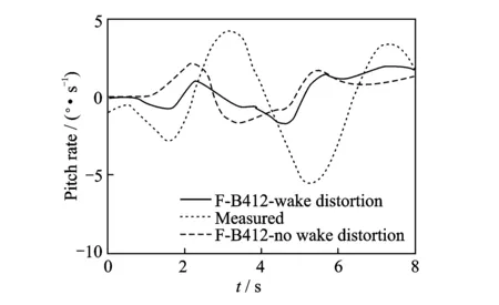
Fig.3 Bell 206 lateral off-axis response[17]
2.2 Pitt-Peters dynamic inflow model and Peters-He finite state inflow model
Krothapalli, et al.[35-40]studied the rotor wake distortion effect during helicopter maneuvering flight by using various analytical tools, and finally obtained a generalized dynamic wake model with quasi-steady wake curvature augmentation in hover. Using the extended generalized wake model coupled with a rigid blade flapping model, the simulated off-axis flapping response to both longitudinal and lateral cyclic control stick inputs have shown fairly well qualitative results, when compared with the Sikorsky bearingless main rotor (SBMR) wind tunnel test data.
He[41]adopted a full span prescribed vortex wake model consisting of discrete trailing and shed vortex elements to model the rotor wake geometric distortion effect during a pitch and/or roll rate. This rotor geometric wake distortion effect was implemented in a comprehensive rotorcraft simulation program, FLIGHTLAB, and simulated control response of a UH-60 Black Hawk helicopter to a lateral cyclic control stick doublet input in hover was compared with the corresponding flight test data. The comparison showed that the correlation of the off-axis pitch rate response prediction to a lateral cyclic control stick doublet input with flight test data was improved, although the magnitude was under predicted. In Ref.[16], the enhanced Peters-He finite state dynamic inflow model was integrated into the F-B412 model in FLIGHTLAB. It has been found that the pitch/roll off-axis responses in manoeuvres could be improved by including the wake geometry distortion effect in the Peters-He finite state dynamic inflow model, as Fig.4 shows.
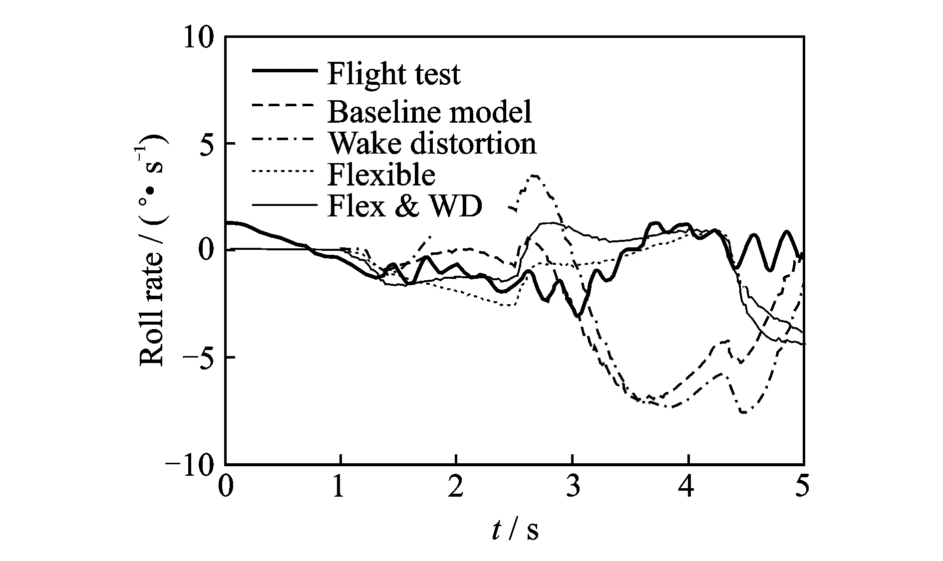
Fig.4 Off-axis response with and without wake distortion effet
2.3 Free wake model
Although the dynamic inflow model of Peters et al.[15]has found wide usage, there are known limitations. There are certain flight conditions in which the assumptions of the finite state inflow break down, for example, in certain descending flight conditions or vortex ring state. On the other hand, free-vortex wake models are inherently capable of modeling all important wake distortion effects and well suited for modeling wake-empennage interactions. The basic assumptions of the free-vortex models are perfectly valid for all generalized flight maneuvers, including descending flight conditions and large amplitude maneuvers. It is computationally expensive and therefore, not suitable for real-time applications. However, with advances in computing power, efficient free-vortex algorithms, and parallel processing, it is now feasible to use free wakes in real-time simulation.
The first major contribution to the understanding of the off-axis response correlation discrepancy problem came from Rosen and Isser[43-44]. Rosen and his colleagues used a complex dynamic model of the rotor wake to show that a geometric distortion of the rotor wake structure occurred under a steady rotor shaft pitch and/or roll motion. This distorted rotor wake geometry induced a lateral inflow gradient perturbation across the rotor disk for a roll motion and a longitudinal inflow gradient perturbation for a pitch motion, which was counter to the kinematic inflow perturbation due to the shaft pitch and/or roll rate. Therefore, they proposed that this inflow change caused by the wake geometric distortion effect could yield a sign reversal in the off-axis flapping response in hover condition. Through including the wake geometric distortion effect during a pitch and/or roll maneuver in their unsteady aerodynamic model (TEMURA), a signi-ficant improvement in the off-axis response correlation with a UH-60 Black Hawk helicopter flight test identification results was achieved.
Bagai et al. and Bhagwat et al.[31,45-47]used a free vortex method for the rotor wake to study the aerodynamics of a helicopter undergoing a steady pitch and/or roll maneuver. Through solving the rotor wake geometry under a prescribed pitch and/or roll rate using either a five-point central difference algorithm or a time accurate free vortex algorithm[46-47], it has been shown that the rotor pitch and/or roll maneuver was an additional source of distortion to the rotor wake geometry in both hover and forward flight. However, the wake distortion effect strongly depended on flight condition. In hover and low speed forward flight, the distorted rotor wake geometry caused by the pitch and/or roll maneuver induced an inflow gradient across the rotor disk, which was proportional to the rotor pitch and/or roll rate and manifests as a counter effect to the kinematic inflow across the rotor disk. At higher advance ratios, the effect of maneuver induced wake distortion is still existed, but was reduced by about half of that in hover condition.
Theodore and Celi[48]investigated the effect of rotor wake modeling on the prediction of the off-axis response to pilot cyclic control stick input by incorporating a free wake model for helicopters with both a hingeless and an articulated rotor configuration and compared the simulation results with available flight test data. Although some improvements on the initial off-axis response prediction have been achieved, their results suggesed that deficiencies still existed in the wake model, and that other aerodynamic mechanism associated with the rotor wake dynamics might play a role in affecting the off-axis dynamic response correlation. They suggested that these mechanisms potentially might include the effect of unsteady aerodynamics and the transient effect associated with the development of the wake itself.
Wachspress and Quackenbush[42]demonstrated the potential for using free wake models in real-time simulation. Then Rosen and Isser[43]showed the CHARM free wake model, integrated with the GENHEL simulation model, finally used in low-cost real-time simulator[19]. The CHARM free-vortex wake model was integrated with the GENHEL flight dynamics simulation of the UH-60A helicopter[49]. Fig.5 shows the schematic of GENHEL and CHARM coupling procedure.
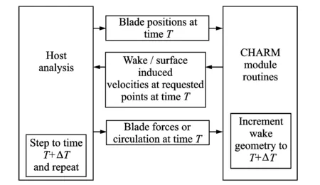
Fig.5 Schematic of GENHEL/CHARM coupling procedure[48]
A high fidelity wake model was defined by increasing the spatial and temporal resolution of the wake until a converged response was observed, but this baseline model could not execute in real-time. A parametric study was performed to find the best combination of wake parameters to achieve real-time execution with minimal deviation from the baseline model in terms of the frequency and time responses in the pitch and roll axes. A real-time model was found and showed reasonable agreement with the baseline model as compared to a simple finite-state inflow model (Fig.6).
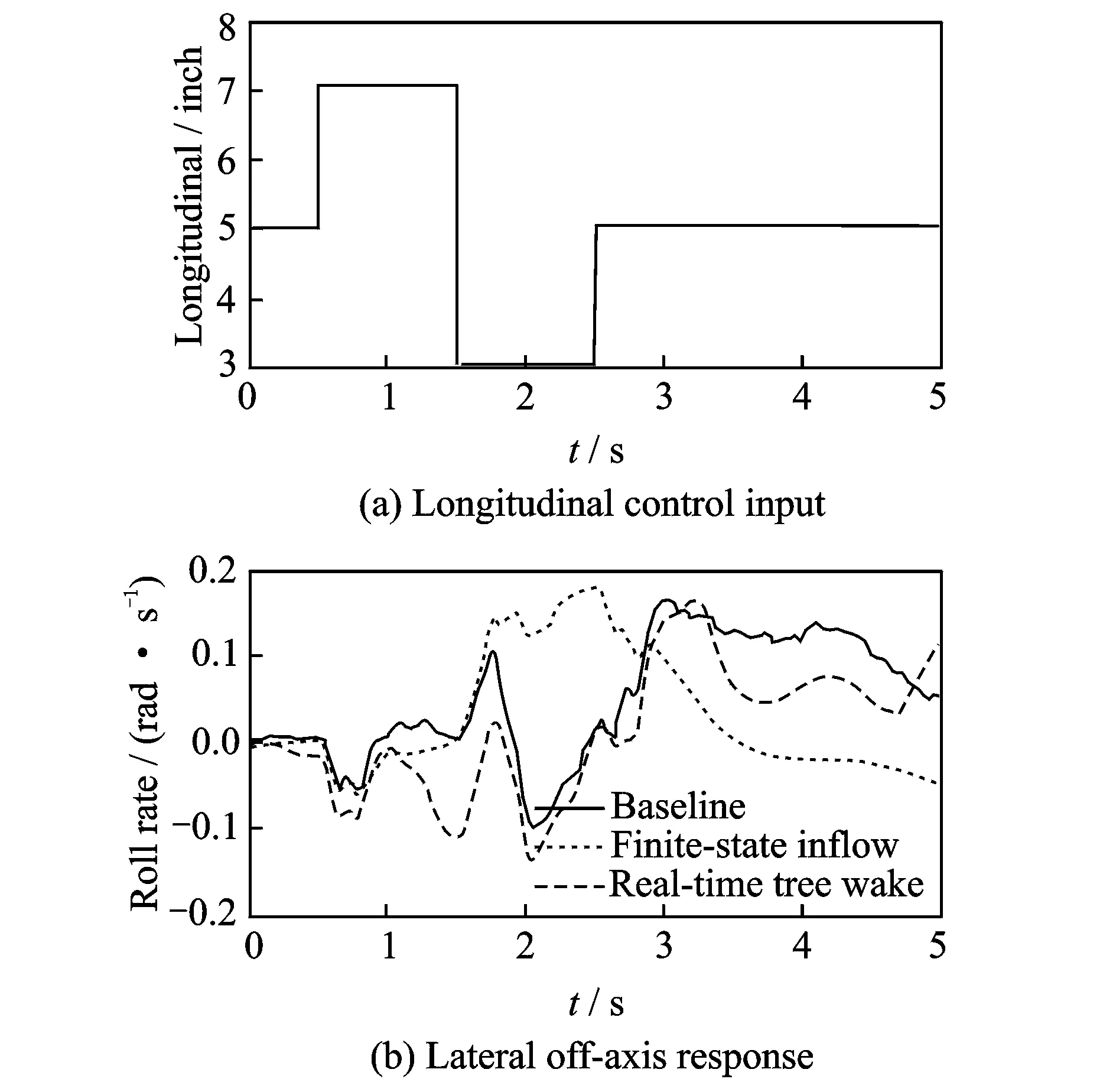
Fig.6 Lateral off-axis response of real-time wake model[48]
A parallel implementation of the free wake model was also investigated. The dynamic model with free wake model for flight simulator cause increased fidelity for real-time simulation and the use of first-principles/physics-based models in real-time flight simulation. Thus, the flight dynamics models could be used more as a predictive tool and not rely as much on empirical models.
3 Conclusions
The dynamic model for helicopter flight simulator has becone increasingly complex, from the simple mathematical model with uniform inflow, like ARMCOP model, to component-type complex model with flexible blades and free wake model, like UTIAS model which has improved the off-axis response situation.
In future, with advances in computing power, efficient algorithms, parallel processing and developing helicopter dynamics theory, more and more complex dynamic model even coupled with computational fluid dynamics (CFD) calculating for rotor wake and aerodynamic interference, full finite element blade model will be developed for flight simulator.
For training simulator, we will focus on helicopter special situation model such as hazard airflow[1], rortex ring state(VRS)[50], icing[51]and so on. The special situation model coupled with dynamic model will be the next key development.
Acknowledgements
This work was supported by the Fundamental Research Funds for the Central Universities; and the Research Innovation Program for College Graduates of Jiangsu Province (No.KYLX_0294).
[1] ARAGON C R, LONG K R. Airflow hazard visualization for helicopter pilots: Flight simulation study results[C]//American Helicopter Society 61st Annual Forum. Grapevine, TX: AHS, 2005:61(1): 1.
[2] PADFIELD G D, WHITE M D. Flight simulation in academia-HELIFLIGHT in its first year of operation at the University of Liverpool[J]. Aeronautical Journal, 2003, 107(1075):529-538.
[3] FAA AC 120-63, Helicopter simulator qualification [S]. [S.l.]: Federal Aviation Administration, 1994.
[4] JAR STD 1H. Helicopter flight Simulators[S]. The Netherlands: Joint Aviation Authorities, Hoofddorp, 2001.
[5] TOLER J R, MCINTYRE W. Simulation of helicopter and v/stol aircraft. Volume I: Helicopter analysis report: NAVTRADEVCEN 1205-1[R]. 1963.
[6] HOUCK J A, GIBSON L H, STEINMETZ G G. A real-time digital computer program for the simulation of a single rotor helicopter:NASA TM X-2874[R]. 1974.
[7] TALBOT P D, TINLING B E, DECKER W A, et al. A mathematical model of a single main rotor helicopter for piloted simulation:NASA TM-84281[R]. 1982.
[8] HILBERT K B. A mathematical model of the UH-60 helicopter:NASA TM-85890 [R]. 1984.
[9] HOWLETT J J. UH-60A black hawk engineering simulation program. Volume 1: Mathematical model:NASA CR-166309[R]. 1981.
[10]BALLIN M G. Validation of a real-time engineering simulation of the UH-60A helicopter:NASA TM-88360[R]. 1987.
[11]HARDING J W, BASS S M. Validation of a flight simulation model of the AH-64 apache attack helicopter against flight test data[C]// American Helicopter Society 46th Annual Forum. Washington, D C: AHS,1990: 1309-1325.
[12] HARRISON J M. An integrated approach to effective analytical support of helicopter design and development[C]// 6th European Rotorcraft and powered Lift Aircraft Forum. Bristol, England: Bristol University, 1980: 1-19.
[13]MANSUR M H. Development and validation of a blade-element mathematical model for the AH-64A Apache helicopter:NASA TM-108863[R]. 1995.
[14]GUBBELS A W, CARIGNAN S, ELLIS D K. The NRC bell 412 advanced systems research aircraft—A new facility for airborne simulation[J]. Canadian Aeronautics and Space Journal, 2000, 46(2):106-115.
[15]PETERS D A, HE C J. Finite state induced flow models. II-three-dimensional rotor disk[J]. Journal of Aircraft, 1995, 32(2):323-333.
[16]MANIMALA B, WALKER D, PADFIELD G. Rotorcraft simulation modelling and validation for control design and load prediction[C]//31st European Rotorcraft Forum. Florence, Italy: AHS,2005: 13-15.
[17]HAYCOCK B, GRANT P. A real-time helicopter model with flexible main rotor blades[C]//AIAA Modeling and Simulation Technologies Conference. Portland, Oregon: AIAA, 2011: 6278.
[18]HAYCOCK B, GRANT P. Dynamic wake distortion in the utias real-time helicopter models[C]//AIAA Modeling and Simulation Technologies Conference. Toronto, Ontario, Canada: AIAA, 2010: 8212.
[19]HORN J F, BRIDGES D O, LOPES L V, et al. Development of a low-cost, multi-disciplinary rotorcraft simulation facility[J]. Journal of Aerospace Computing, Information, and Communication, 2005, 2(7):267-284.
[20]CARPENTER P J, FRIDOVICH B. Effect of a rapid blade-pitch increase on the thrust and induced-velocity response of a full-scale helicopter rotor:NACA-TN-3044[R]. 1953.
[21]GAONKAR G H, PETERS D. Review of dynamic inflow modeling for rotorcraft flight dynamics[J]. Vertica, 1988, 12(3):213-242.
[22]CHEN R T N. A survey of nonuniform inflow models for rotorcraft flight dynamics and control applications:NASA-TM-102219[R]. 1989.
[23]SHERARD S, REID L. The effects of simulator motion on handling qualities[C]// AIAA Modeling and Simulation Technologies Conference and Exhibit. Austin, Texas: AIAA,2003:5677.
[24]ESHOW M M, ORLANDI D, BONAITA G, et al. Results of an A109 simulation validation and handling qualities study:NASA-TM-101062[R]. 1990.
[25]TAKAHASHI M D. A flight-dynamic helicopter mathematical model with a single flap-lag-torsion main rotor:NASA-TM-102267[R]. 1990.
[26]HARDING J W, BASS S M. Validation of a flight simulation model of the AH-64 Apache attack helicopter against flight test data[C]//46th American Helicopter Society Annual Forum. Washington D.C.:AHS,1990: 1309-1325.
[27]CHAIMOVICH M, ROSEN A, RAND O, et al. Investigation of the flight mechanics simulation of a hovering helicopter[C]//48th American Helicopter Society Annual Forum. Washington D.C.:AHS,1992: 1237-1256.
[28]HE C, LEWIS W. A parametric study of real time mathematical modeling incorporating dynamic wake and elastic blades[C] //48th American Helicopter Society Annual Forum. Washington D.C.:AHS,1992: 1181-1196.
[29]TISCHLER M B, DRISCOLL J T, CAUFFMAN M G, et al. Study of bearingless main rotor dynamics from frequency-response wind tunnel test data[C]//Aeromechanics Specialists Conference on Aerodynamics, Acoustics and Dynamics. San Francisco, CA: [s.n.],1994:6.
[30]THEODORE C, CELI R. Helicopter flight dynamic simulation with refined aerodynamics and flexible blade modeling[J]. Journal of Aircraft, 2002, 39(4):577-586.
[31]BAGAI A, LEISHMAN J G, PARK J. Aerodynamic analysis of a helicopter in steady maneuvering flight using a free-vortex rotor wake model[J]. Journal of the American Helicopter Society, 1999, 44(2):109-120.
[32]TURNOUR S R, CELI R. Modeling of flexible rotor blades for helicopter flight dynamics applications[J]. Journal of the American Helicopter Society, 1996, 41(1):52-66.
[33]SCHMIDT D K, RANEY D L. Modeling and simulation of flexible flight vehicles[J]. Journal of Guidance, Control, and Dynamics, 2001, 24(3):539-546.
[34]ALFRED J S. Rotorcraft brownout mitigation through flight path optimization using a high fidelity rotorcraft simulation model[D].USA:University of Maryland, 2012.
[35]BAROCELA E B, PETERS D A, KROTHAPALLI K R, et al. The effect of wake distortion on rotor inflow gradients and off-axis coupling[C]// 22nd Atmospheric Flight Mechanics Conference. New Orleans, Louisiana:AIAA, 1997:272-282.
[36]BAROCELA E B.The effect of wake distortion on dynamic inflow for lifting rotors[D]. St. Louis, Missouri: Washington University, 1997.
[37]KROTHAPALLI K R, PRASAD J V R, PETERS D A. Improved wake geometry model for a maneuvering rotor[C]// Atmospheric Flight Mechanics Conference of the American Institute of Aeronautics and Astronautics. San Diego, CA:AIAA,1996:29-31.
[38]KROTHAPALLI K R, PRASAD J V R, PETERS D A. Development of a comprehensive wake theory for lifting rotors[C]// 21st Atmospheric Flight Mechanics Conference. San Diego, California: AIAA, 1996:767-772.
[39]KROTHAPALLI K R. Helicpoter rotor dynamic inflow modeling for maneuvering flight[D]. Atlanta,Georgia: Georgia Institute of Technology, 1998.
[40]KROTHAPALLI K R, PRASAD J V R, PETERS D A. Helicopter rotor dynamic inflow modeling for maneuvering flight[J]. Journal of the American Helicopter Society, 2001, 46(2):129-139.
[41]HE C, LEE C S, CHEN W. Rotorcraft simulation model enhancement to support design, testing and operational analysis[J]. Journal of the American Helicopter Society, 2000, 45(4):284-292.
[42]WACHSPRESS D A, QUACKENBUSH T R, BOSCHITSCH A H. First-principles free-vortex wake analysis for helicopters and tilt rotors[C]// 59th American Helicopter Society Annual Forum. Phoenix, Arizona:AHS, 2003, 59(2): 1763-1786.
[43]ROSEN A, ISSER A. A new model of rotor dynamics during pitch and roll of a hovering helicopter[J]. Journal of the American Helicopter Society, 1995, 40(3):17-28.
[44]ROSEN A, ISSER A. A model of the unsteady aerodynamics of a hovering helicopter rotor that includes variations of the wake geometry[J]. Journal of the American Helicopter Society, 1995, 40(3):6-16.
[45]PARK J S, LEISHMAN J G. The investigation of unsteady aerodynamics on rotor wake effects in maneuvering flight[J]. Annual Forum Proceedings—American Helicopter Society, 1999, 55(1):467-480.
[46]BHAGWAT M J, LEISHMAN J G. Rotor aerodynamics during maneuvering flight using a yime-accurate free-vortex wake[J]. Journal of the American Helicopter Society, 2003, 48(3):143-158.
[47]BHAGWAT M J. Mathematical modeling of the transient dynamics of rotor wakes using a time-accurate free vortex method[D]. College Park, MD: University of Maryland at College Park, 2001.
[48]THEODORE C, CELI R. Prediction of the off-axis response to cyclic pitch using a maneuvering free wake model[C]// 25th European Rotorcraft Forum. Rome, Italy:AHS, 1999.
[49]HORN J F, BRIDGES D O, WACHSPRESS D A, et al. Implementation of a free-vortex wake model in real-time simulation of rotorcraft[J]. Journal of Aerospace Computing, Information, and Communication, 2006, 3(3):93-107.
[50]CHEN C. Development of a simplified inflow model for a helicopter rotor in descent flight[D]. Atlanta, Georgia: Georgia Institute of Technology, 2006.
[51]AVANZINI G, de MATTEIS G, CISTRIANI L, et al. Development of a simplified helicopter model for piloted training simulation[C]//AIAA Modeling and Simulation Technologies Conference. Portland, Oregon:AIAA, 2011: 6280.
Prof. Gu Hongbin is the head of Center for Flight Simulation and Advanced Technology for Training at Nanjing University of Aeronautics and Astronautics (NUAA). He received his Ph.D Degree in Aerospace from in 2000. His current research interest is flight simulation and advanced technology for training, such as computer based training and virtual reality.
Mr.Fu Jun was born in Zhejiang, in 1990. He is currently a Ph.D. candidate in Traffic and Transportation Engineering, College of Civil Aviation Engineering, NUAA. His research interests include helicopter dynamics modeling and atmosphere turbulence modeling.
Mr.Hu Jinshuo was born in Shandong, in 1988. He is currently a Ph.D. candidate in Traffic and Transportation Engineering, College of Civil Aviation Engineering, NUAA. His research interests include flight control simulation, nonlinear control system design, and applications of advanced control techniques to air vehicles.
(Executive Editor: Zhang Bei)
V275 Document code:A Article ID:1005-1120(2016)06-0647-10
*Corresponding author, E-mail address: ghb@nuaa.edu.cn. How to cite this article: Gu Hongbin, Fu Jun, Hu Jinshuo. Review on key techniques of dynamics modeling for helicopter simulator[J]. Trans. Nanjing Univ. Aero. Astro., 2016,33(6):647-656. http://dx.doi.org/10.16356/j.1005-1120.2016.06.647
杂志排行
Transactions of Nanjing University of Aeronautics and Astronautics的其它文章
- A Sequential Adaptive Method for Enhancing DOA Tracking Performance
- A Directional Differential-Fed UWB Antenna with Stable Radiation Pattern
- Numerical Simulation of An Axial Flow Fan with Proper Aft Fins for Floating Wind Turbines Model Test
- Capacity Analysis on Distributed Antenna System with Imperfect CSI over Rayleigh Fading Channel
- Acknowledgement to Reviewers
- TRANSACTIONS OF NANJ ING UNIVERSITY OF AERONAUTICS AND ASTRONAUTICS
