CFD Computation of Added Resistance for KVLCC2 Model in Head Short Waves
2015-12-13WUChengshengYANDaijunQIUGengyaoNIYang
WU Cheng-sheng,YAN Dai-jun,QIU Geng-yao,NI Yang
(National Key Laboratory of Science and Technology on Hydrodynamics,China Ship Scientific Research Center,Wuxi 214082,China)
0 Introduction
In the last decade,a lot of legislations about the effect of shipping trade on global environment were introduced by many international organizations,e.g.IMO,UN,etc.So many efforts have been focused on the study of the performance of ships operating in seaway.
The prediction of added resistance of a ship in waves is essential to evaluate the ship performance in seaway.One of the first attempts to obtain the added resistance value of a ship was carried out by Havelock(1942).The next relevant significant contribution to the analytical calculation of the added resistance is developed by Maruo(1957)with a potential flow solution.From then on,a lot of research work has been done for added resistance based on potential flow theory[1].
According to the classical sea-keeping theories,the energy dissipated of a ship in waves can be attributed to three different components.These three components are:
(1)The first component obtained from the interference between incident waves which are diffracted when encountering ship hull,and the radiated waves produced by ship motions,es-pecially those caused by heave and pitch.This component is called drifting force.
(2)The incident waves are also reflected on ship hull,and also interact with the ship radiated waves.This second component is called diffraction effect.
(3)A‘viscous’effect due to the damping of the vertical motions.
Traditional calculations and measurements indicate that the drifting force,caused by the ship motions radiated waves,would make the largest contribution to the added resistance,whereas diffraction effects would be the least significant,which is more important for short waves.
Nowadays,some of the modern ships are very large,for example,a VLCC(Very Large Crude-oil Carrier)will exceed 320 m in length.That means when the VLCC travelling in normal sea states,most of the encountering waves can be considered as short waves.So the prediction of added resistance for ships in short waves is now a hot topic.
For ships in short waves,diffraction effect is rather important to the added resistance,whereas considered as the least significant and cannot be well modeled(or even neglected)in traditional calculating method based on potential flow theory.On the contrary,ship motion responses in short waves are usually very small,which means the added resistance caused by the ship motions radiated waves will be insignificant.So the traditional potential flow theory based methods will not work well on the prediction of added resistance for very large ships[2].
CFD method based on the solution of RANSE(Reynolds Averaged Navier-Stokes Equations)may overcome the limitation of the potential flow theory based method with respect to the effects of water viscosity,wave dispersion,nonlinearity and wave breaking.Consequently,the application of RANSE based CFD method in the ship industry is increasing.
Prediction of flow field around ship hulls using RANSE based CFD method started in the 1980s,and the majority of the studies were initially devoted to ship resistance and flow field prediction in steady state.In the late 1990s,a few sea-keeping computations with CFD had been performed[3].From then on,some efforts have focused on CFD prediction of sea-keeping performance of ships,including ship motions and added resistance[4-7].
However,there are few published papers on CFD computation of added resistance in short waves.One of the most challenges in the CFD computation is the simulation of short waves with high quality.As we know,waves with high steepness are unstable and short waves with low steepness will be subjected to more time and spatial variation than long waves.Furthermore,short waves will decay excessively in CFD computation due to numerical dissipation,and the additional damping caused by ill-suited meshes and settings will even make the condition worse.
The research work in this paper focused on the added resistance in short waves.CFD computations of added resistance for KVLCC2 model advancing in regular head short waves were carried out by RANSE based numerical wave tank technology.The computed results were compared with experimental data and showed quite good agreement.The added resistance at different parts was also investigated,and the results indicated that the added resistance is primarily concentrated at the fore-segment,whereas the mid-and aft-segments contribute little to added resistance.
1 Ship geometry and test cases
The KVLCC2 model with scale of 44.444 is adopted for the CFD computations.Main particulars of the ships are given in Tab.1.Fig.1 shows the hull geometry of KVLCC2.The depth of the model hull is increased to 0.785 m to avoid water on deck.The model hull is divided into 3 segments for the investigation of added resistance at different parts.Fig.2 shows the segmented hull form.The resistance on each segment was monitored in CFD computations.

Tab.1 Main particulars of KVLCC2

Fig.1 Hull geometry of KVLCC2

Fig.2 Segmented hull form
The waves used for the computations are given in Tab.2.The CFD computations only cover the range of short waves(λ/LPP=0.20~0.60).The advancing speeds of the model are 0.772 m/s(Fr=0.092)and 1.196 m/s(Fr=0.142),the corresponding full scale ship speeds are 10.0 kns and 15.5 kns,respectively.
Many experimental studies on added resistance in waves for KVLCC2 have been done by some groups with different scaled models.The majority of the studies covered the range of intermediate and long waves,whereas few studies focused on short waves.Thus Guo and Steen’s experimental study on added resistance of KVLCC2 in short waves[8-9]is quite valuable.In this paper,the experimental data used for the validation of computed results in short waves is referred to Guo and Steen’s study.
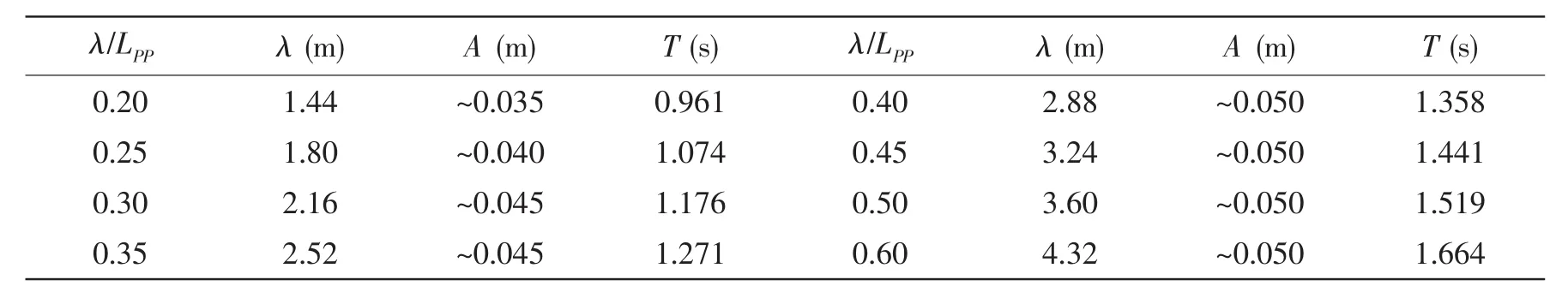
Tab.2 Waves used for computations
2 Computation method
2.1 Mathematical model and numerical method
The CFD computations are performed by solving RANS equations,RNG k-ε two-equation model is employed for the enclosure of the governing equations.The VOF(volume of fluid method)method is adopted for the treatment of nonlinear free surface.The detailed descriptions about the governing equations can be referred to Refs.[6-7].
The governing equations are discretized by Finite Volume Method(FVM),the secondorder upwind difference scheme was adopted for the convection term and the centric difference scheme for the dissipation term.Multi-grid acceleration and SIMPLE(Semi-Implicit Method for Pressure Linked Equations)algorithms are used for solving the difference equation system.
The incident waves are generated from the inflow boundary by prescribing a wavy velocity profile.The outgoing waves are dissipated inside an artificial damping zone located at the rear part of the computational domain.It can also be referred to Refs.[6-7]for the details of wave generation and absorption in numerical simulations.
2.2 Computational domain and boundary conditions
The origin of the coordinate system for the computational domain locates on the intersection of calm water surface,symmetric plane and vertical-transverse mid-plane of the hull.The computational domain’s extents are:-1.7LPP~3.0LPPin x-direction including damping zones with length of about 1.5LPP,-1.2LPP~1.2LPPin y-direction and-1.2LPP~0.4LPPin z-direction.Only half of the ship hull is used in the computation,thus a‘symmetry’boundary condition is adopted at the center plane of the domain.
The boundary of the computational domain is composed of inlet boundary,outlet boundary,wall boundary(hull surface),and outer boundary(include bottom,proof and side of the domain).On the inlet boundary,a velocity profile resembling flexible flap wave-maker motions and volume fraction are prescribed.On the outlet boundary,the free surface here is assumed to be calm after the waves pass through the artificial damping zone and the hydrostatic pressure is set.On the surface of ship hulls,the standard wall function is introduced.On the outer boundary,zero stress is specified.
The computational domain is discretized by H-O type multi-block structural mesh.There are at least 30 cells per wave length in x-direction for the shortest waves,10~20 cells within the region of wave height.The mesh near the bow and stern and around the ship hull is refined locally in order to well solve the complex flow around the hull,while the mesh becomes coarser towards the outer and outlet boundary.The y+is about 50 in general except some areas of bow and stern.Fig.3 shows the computational domain and mesh.
As ship motion responses in short waves are usually insignificant,the added resistance caused by the ship motions can be neglected.So in CFD computations,the hull is fixed and without motion responses to the incoming waves.

Fig.3 Computational domain and mesh
3 Computational results
3.1 Simulation of short waves
As mentioned before,one of the most challenges in the CFD computation is the simulation of short waves with high quality.So the simulation results of short waves will be presented firstly.
The wave patterns of KVLCC2 advancing in regular head waves with wave lengths of 0.2LPP(left)and 0.3LPP(right)are presented in Fig.4.As can be seen from the figure,for wave with λ/LPP=0.20,the wave decays a little when propagating from the inlet boundary to the ship stern,while within the range from ship bow to stern,the wave maintains quite stable and the decay is insignificant.For wave with λ/LPP=0.30,the wave is very stable when propagating from the inlet boundary to the ship stern and the decay can be neglected.Waves will decay quickly after propagating into the damping zone.

Fig.4 Wave patterns for KVLCC2 advancing in head waves
The wave in the region occupied by the ship is more important to added resistance than in the whole computational domain.Fig.5 gives the wave profile for wave with λ/LPP=0.20 within the range from ship bow and stern.From the figure we can see that the decay of the wave is insignificant and can be neglected.For longer waves,the decay will be even less.

Fig.5 Wave profile for wave with λ/LPP=0.20
The simulation results indicate that the quality of the simulated short waves is quite satisfactory for the computation of added resistance.
3.2 Added resistance
The non-dimensional added resistance could be expressed as,
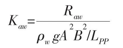
The added resistance for KVLCC2 in head short waves at Fr=0.092(left)and Fr=0.142(right)computed by CFD method are depicted in Fig.6(solid square points).The experimental data are also plotted in the figure(hollow circular points).
It can be seen from the figure that the computed results agree with the experimental data quite well.The ship motion responses are insignificant in short waves and hence their contribution to added resistance is negligible.So the added resistance in short waves computed by CFD method is quite accurate even when the model hull is fixed and without motion responses to incoming waves.

Fig.6 Added resistance computed by CFD method
Because more and more attentions are paid on the performance of ship operating in seaway,the objective of hull form optimization is turning to improving powering performance in waves now.The primary way to achieve this goal is to minimize the added resistance in waves.
The added resistance at different parts of the model hull is investigated to provide some guidance to hull form optimization in waves.The computed added resistance for different segments of the hull at Fr=0.092(left)and Fr=0.142(right)is shown in Fig.7(solid points).The experimental data are also presented in the figures(hollow points).
The figures indicate that the added resistance is primarily concentrated at the fore-segment,whereas the added resistance at the aft-segment is rather small,while the contribution from the mid-segment can be neglected.

Fig.7 Added resistance at different hull segments
Fig.8 shows the wave pattern for the KVLCC2 model advancing in head short wave(λ/LPP=0.20).As can be seen from the figure,some strong nonlinear phenomena,such as wave rolling up and wave break near the ship bow can be captured by CFD simulation.

Fig.8 Wave pattern for KVLCC2 advancing in head wave—bow view(λ/LPP=0.20)
4 Conclusions
CFD computations of added resistance for KVLCC2 model advancing in head short waves with different speeds were carried out in this paper.Added resistance at different parts of the ship hull was also investigated by dividing the hull into three segments and monitoring the resistance of each segment in CFD computations.Some conclusions can be drawn according to the analysis of computed results:
(1)CFD computation can predict added resistance of ship heading in short waves quite accurately even while the model hull is fixed and without motion responses to the incoming waves.
(2)Added resistance of ship heading in waves is primarily concentrated at the fore-segment,whereas the aft-segment contributes a little to the added resistance,while the contribution from the mid-segment can be neglected.
(3)Some strong nonlinear phenomena,such as wave rolling up and wave break near the ship bow can also be captured by CFD simulation.
The research work in this paper indicates that CFD can be an effective tool for the investigation and prediction of added resistance in short waves.
[1]Pérez Arribas F.Some methods to obtain the added resistance of a ship advancing in waves[J].Ocean Engineering,2007,34:946-955.
[2]Wu Chengsheng,Lu Jiang,Yan Daijun Bu Shuxia,Qiu Gengyao.A combined viscous and potential method for the computation of added resistance in head waves[C]//Proceeding of the 11th International Conference on Hydrodynamics.Singapore,2014.
[3]Wilson R,Paterson E,Stern F.Unsteady RANS CFD for naval combatants in waves[C]//Proceedings of the 22nd Symposium on Naval Hydrodynamics.Washington D.C.,USA,1998.
[4]Hochbaum A C,Vogt M.Towards the simulation of seakeeping and manoeuvring based on the computation of the free surface viscous ship flow[C]//Proceedings of the 24th Symposium on Naval Hydrodynamics.Fukuoka,Japan,2002.
[5]Luquet R,Gentaz L,Ferrant P,Alessandrini B.Viscous flow simulation past a ship in waves using the SWENSE approach[C]//Proceedings of the 25th Symposium on Naval Hydrodynamics.St.John’s,Newfoundland and Labrador,Canada,2004.
[6]Wu Chengsheng,Zhu Dexiang,Gu Min.Computation of hydrodynamic forces for a ship in regular heading waves by a viscous numerical wave tank[J].Journal of Ship Mechanics,2008,12(2):168-179.
[7]Wu Chengsheng,Zhu Dexiang,Gu Min.Development of a viscous numerical wave tank and simulation of wave induced motions for a ship in regular head waves[C]//Proceeding of the 8th International Conference on Hydrodynamics.Nantes,France,2008.
[8]Guo B J,Steen S.Experiment on added resistance of a ship moving in short waves[C]//Proceedings of the 28th Symposium on Naval Hydrodynamics.California,USA,2010.
[9]Guo B J,Steen S.Evaluation of added resistance of KVLCC2 in short waves[J].Journal of Hydrodynamics,2011,23:709-722.
杂志排行

船舶力学的其它文章
- Stress Field Analysis of 135-degree Sharp Corners Based on Notch Stress Strength Theory
- Review on Advances in Research of Ice Loads on Ice-going Ships
- Identification Method for Exciting Force Source Inside Underwater Structure Based on PSO_GA
- Vibration Response Analysis of an Underwater Submersible
- Research on Numerical Simulation of Ship-ice Collision Based on MD Nastran
- Design of Energy Harvesting Efficiency of‘Haiyuan 1’Wave Power Generating Platform’s Buoy Testing System based on LabVIEW