Vibration Response Analysis of an Underwater Submersible
2015-12-12SUNJiangangZOUMingsong
SUN Jian-gang,ZOU Ming-song
(China Ship Scientific Research Center,Wuxi 214082,China)
0 Introduction
Ship hydroelasticity theories were established in the 1970s,which took the elastic deformation of the ship structure into account in view of dynamics and took the elastic hull and the surrounding flow field as an inseparable and interactive entirety.The three-dimensional hydroelasticity theories nowadays have been widely applied in ship and ocean engineering field such as,loads and safety assessment of ships traveling in a seaway,fatigue analysis,pounding response,vibration and acoustic radiation underwater,etc.
Bishop and Price et al[1]established the two-dimensional hydroelasticity theory based on the strip-beam theory,which provided a method to safety assessment of a slender ship in waves.The same concept was employed to combine the three-dimensional potential theory and the three-dimensional structural dynamics by Wu[2],Price and Wu[3]to produce a generalized three-dimensional hydroelasticity theory for fluid-structure interactions of an arbitrary floating body in waves.Different from the two-dimensional hydroelastic theory,the three-dimensional hydroelastic theory can be applied to wide range of fluid-structure interaction problems of small length-width ratio ship,multi-hull ship,ocean platform,etc.Du[4]proposed rapid calculation method to achieve the 3D pulsating source Green’s function with zero forward speed,so that the three-dimensional hydroelastic calculation work can be implemented by computer,which promoted the development of the theory to practical application.Xia and Wu[5]proposed the general form of boundary conditions on the fluid-structure interface considering the influence of the surface tension strain.Wu and Du[6]researched the wave induced vibration and wave loads of a Very Large Floating Structure(VLFS).Ye[7]researched the dynamic stress of a Small-Waterplane-Area Twin-Hull Ship(SWATH)traveling in waves.Ye[8]predicted the mechanical impedance and the forced vibration response induced by mechanical equipment on a 1500-ton Small-Waterplane-Area Twin-Hull Ship(SWATH).Zou et al[9]replaced the Green’s function for incompressible fluid with that for uniformly distributed ideal compressible fluid in semi-infinite domain and proposed the structural-acoustic radiation calculated method of threedimensional hydroelasticity with free surface.
1 3D hydroelastic method
Assuming that the motion of the hull has small amplitudes,the displacement can be written in the form

here:m is the limited modal order determined by the required precision,is the r-th modal displacement,qris r-th principal coordinate corresponding to a prescribed motion of the structure.The boundary conditions on the fluid-structure interaction interface is defined as:

here:φ is the velocity potential,is the system nodal velocity,is the normal unit vector of the body surface pointing outwards,is the steady state fluid velocity vector,is rotation vector in the structure.The principle coordinate equation of motion and deflection of the structure can be written as:


here:ρ is the density of fluid,φkis the radiation potential.
2 Numerical model and modal analysis
The submersible structure is about 10 meters in length,about 3 meters in depth,about 70 tons in displacement,and with twi-main engines propulsion system.The numerical model is symmetrical,as shown in Fig.1,in which shell and beam elements are used to simulate the hull structure,and the discrete mass elements to the equipments and the side water.Part of the modal shapes of the dry structure are shown in Fig.2.

Fig.1 The submersible structure

Fig.2 Modal shapes of the dry structure corresponding to the resonant frequencies within the frequency range from 0.1 Hz to 40 Hz
3 Vibration response analysis and the certification
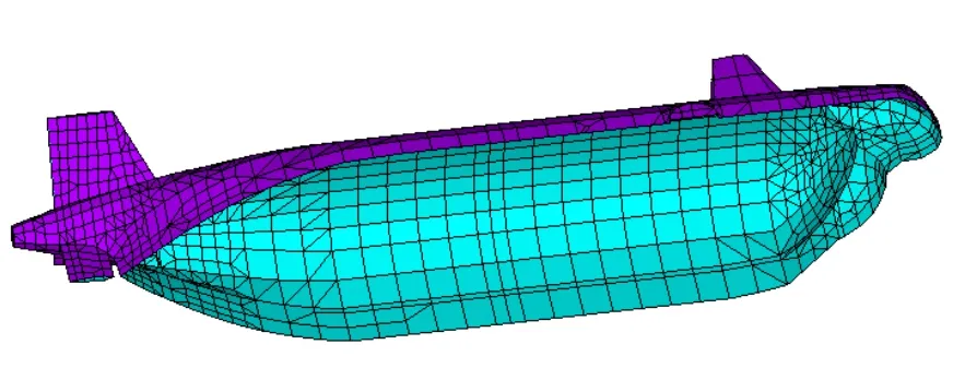
Fig.3 Wetted interface mesh

Fig.4 The amplitude of velocity responses on the stern node of the submersible port structure.(a)Response in vertical direction corresponding to the vertical excitation.(b)Response in transverse direction corresponding to the transverse excitation)
The responses at each of the principal coordinates corresponding to the resonant frequencies of dry structure(see Fig.2)are calculated and plotted,as shown in Fig.5,and from the peaks of the curves in Fig.5 we can obtain the corresponding wet resonance frequency for each dry mode.In many cases there might be apparent multi-peak with similar amplitude in level in the curve,which make it difficult to come to a conclusion,so we turn to the approximate relation that the dry and corresponding wet structure should satisfy shown as follows,to check out the wet resonant frequency at which the dry mode is likely to make the largest contribution among the peaks.

here:fdry,ris the r-th resonant frequency of the structure in vacuum,fwet,ris the wet resonant frequency corresponding to fdry,r,arris the r-th diagonal element of],Arris the r-th diagonal element of
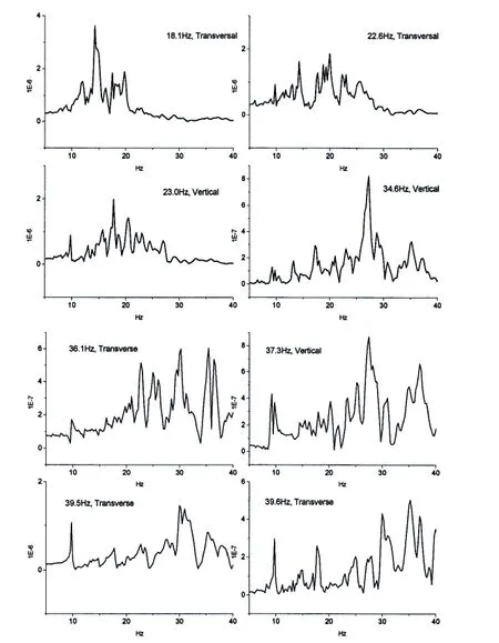
Fig.5 The responses at each of the principal coordinates corresponding to the resonant frequencies of dry structure
The corresponding relationship between resonant frequencies of a submersible structure in vacuum and in water are shown in Tab.1,which illustrates that dry modes at 34.6 Hz and 37.3 Hz in vertical direction,as well as at 36.1 Hz and 39.5 Hz in transverse direction,has the peaks of wet response at the principal coordinates match together at 27.25 Hz and 30 Hz,respectively,due to the effect of the fluid medium.
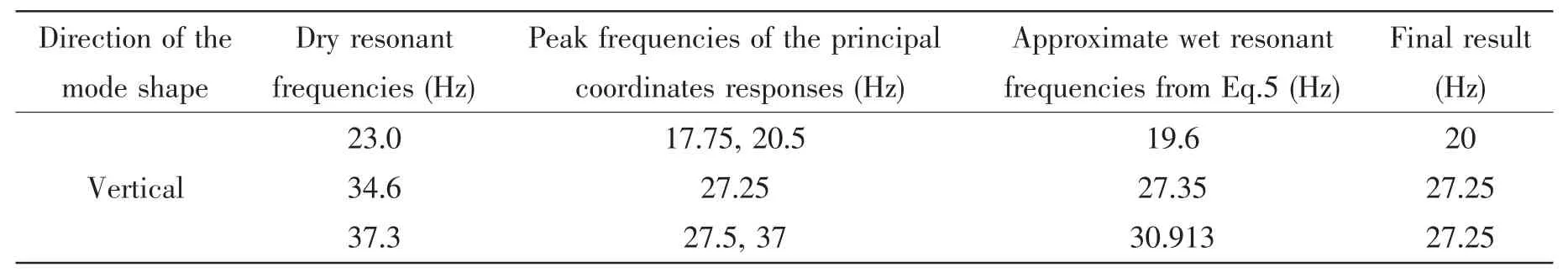
Tab.1 Congruent relation between resonant frequencies of the submersible structure in vacuum and in water

Continue Tab.1
Acoustic test of the submersible structure is implemented in the experimental tank(see Fig.6),and the curves of the radiated sound pressure,in conditions of sailing underwater with one side propeller operating,are obtained as shown in Fig.7.From the curves in Fig.7 we note that the peak appears on the 14 Hz and 29 Hz frequency points in all three operation conditions,and peak appears on the 22 Hz and 36 Hz frequency points in only single condition.Considering again the resonant frequencies of wet hull as shown in Fig.4(or in Tab.1),from which we can conclude that,the predicted values of the resonant frequency of the submersible structure underwater are in good agreement with the test data,although a certain degree of error existed due to the simplified treatment in the model.

Fig.6 Submersible in test
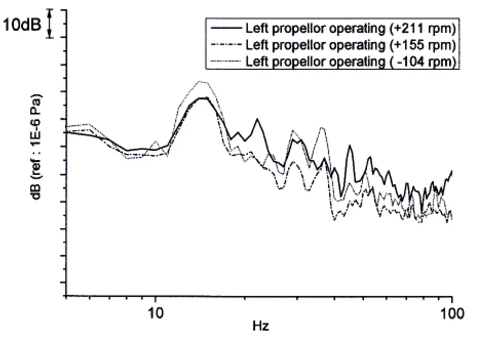
Fig.7 Test data of the radiated sound pressure
4 Improvement of the submersible structure and its evaluation
Considering that most of the vibration shapes corresponding to the peak points of the response curves are the local vibration shapes of the tail structure within the frequency region,the longitudinal structures of the numerical model on both sides,as shown in Fig.8(a),are strengthened for vibration reduction.Closed square tube material is adopted to provide additional buoyancy,subject to the weight restriction of the general arrangement.To reinforce the longitudinal frame can be expected to bring two benefits,firstly,it can enhance the mechanical impedance of the stern structure where the propulsion motor mounted,so as to reduce the import intension of the vibration energy,and secondly,it can make the resonant frequencies of the structure drift to the higher frequency region to keep away from the excitation frequencies usually in low frequency region,such as the rotor shaft frequency,the blade-passing frequency,and their harmonic frequencies.

Fig.8 Stern structure intensification(a)The longitudinal structure before intensification(arrows,on both sides);(b)Reinforcing the each longitudinal by welding two closed square tubes
The former numerical model of the submersible structure is modified based on new program.The vibration responses of the reinforced structure are recalculated with the same parameter setting and compared with the former responses,as shown in Fig.9(a)and Fig.9(b).From Fig.9(a),we observe that in vertical direction,after the improvement,peaks at 20 Hz and 27.75 Hz are eliminated.Moreover,the amplitude in the non-resonant region fall by more than half.From Fig.9(b),we observe that in transverse direction,after the improvement,peaks at 35.25 Hz are eliminated,and the amplitude drop of the response in the non-resonant region is not obvious.The reason is that the reinforced structure is on the neutral axis of bending in most of the local vibration modal shapes in transverse direction(see Fig.2(e),Fig.2(g),and Fig.2(h))and the improvement is not so effective to increase the transverse stiffness,so the side stringer should be also reinforced to achieve better results.
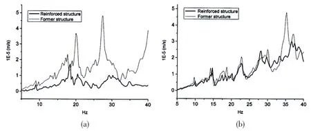
Fig.9 The amplitude of velocity responses on the stern node of the submersible port structure(a)Response in vertical direction corresponding to the vertical excitation;(b)Response in transverse direction corresponding to the transverse excitation
5 Conclusions
Some meaningful results are achieved as follows:
(1)The three-dimensional hydroelastic method was applied to the prediction of the vibration response of the submersible structure,and the predicted wet resonant frequencies were well confirmed by the test.
(2)The corresponding relationship between the dry and wet structures was obtained,which indicates that the dry modes of the submersible structure will possibly cause peaks of response curves at the same frequencies due to the fluid medium.
(3)The optimization of the structure was implemented and remarkably reduced the response level,from which it seems effective to reinforce the longitudinal of the submersible-like frame structure for vibration reduction.
[1]Bishop R E D,Price W G.The generalized antisymmetric fluid forces applied to a ship in a seaway[J].International Shipbuilding Progress,1977,24:3-14.
[2]Wu Y S.Hydroelasticity of floating bodies[D].Brunel University,U.K.,1984.
[3]Price W G,Wu Y S.Structural responses of a SWATH of multi-hulled vessel travelling in waves[C]//Int.Conf.on SWATH Ships and Advanced Multi-hulled Vessels.RINA,London,1985.
[4]Du S X.Direct analysis method for a marine floating structure[D].Wuxi:China Ship Scientific Research Center,1990.
[5]Xia J Z,Wu Y S.One generalized boundary condition on the fluid-structure interaction interface[J].Journal of Ship Performance Research,1993(2):15-22.
[6]Wu Y S,Du S X,Riggs H R,Ertekin R C.Fluid-structure interaction analysis of very large floating structures[M].Aero-Hydroelasticity Developments and Applications,Seismological Press,1993.
[7]Ye Y L,Wu Y S,You G H.Hydroelastic analysis of SWATH ship wave loads[J].Journal of Ship Mechanics,2010,14(12):1340-1348.
[8]Ye Y L.Hydroelastic analysis of the structural vibration and noise radiation of a ship traveling in wave[D].Wuxi:China Ship Scientific Research Center,2012.
[9]Zou M S,Wu Y S,Shen S G,Wu W W.Three-dimensional hydroelasticity with forward speed and free surface in acoustic medium[J].Journal of Ship Mechanics,2010,14(11):1304-1311.
杂志排行

船舶力学的其它文章
- CFD Computation of Added Resistance for KVLCC2 Model in Head Short Waves
- Stress Field Analysis of 135-degree Sharp Corners Based on Notch Stress Strength Theory
- Review on Advances in Research of Ice Loads on Ice-going Ships
- Identification Method for Exciting Force Source Inside Underwater Structure Based on PSO_GA
- Research on Numerical Simulation of Ship-ice Collision Based on MD Nastran
- Design of Energy Harvesting Efficiency of‘Haiyuan 1’Wave Power Generating Platform’s Buoy Testing System based on LabVIEW