Fractional Order Derivative Model of Viscoelastic layer for Active Damping of Geometrically Nonlinear Vibrations of Smart Composite Plates
2015-12-13PriyankarDattaManasRay
Priyankar Datta,Manas C.Ray
Fractional Order Derivative Model of Viscoelastic layer for Active Damping of Geometrically Nonlinear Vibrations of Smart Composite Plates
Priyankar Datta1,Manas C.Ray1
This paper deals with the implementation of the one dimensional form of the fractional order derivative constitutive relation for three dimensional analysis of active constrained layer damping(ACLD)of geometrically nonlinear laminated composite plates.The constraining layer of the ACLD treatment is composed of the vertically/obliquely reinforced 1–3 piezoelectric composites(PZCs).The von Kármán type nonlinear strain displacement relations are used to account for the geometric nonlinearity of the plates.A nonlinear smart finite element model(FEM)has been developed.Thin laminated substrate composite plates with various boundary conditions and stacking sequences are analyzed to verify the effectiveness of the three-dimensional FDM for both the passive and active control authority of the ACLD patch located at the center of the laminates.
Fractional Derivative;Smart Structures;Nonlinear Vibration;Active Control
1 Introduction
Controlling vibration levels in structures under dynamic loading is an important aspect in the study of dynamics and control as high vibration often generates noise and can lead to cyclic fatigue failure of the structure.The drive to use lightweight composite structures,particularly in aerospace,automotive and marine industries,makes them more vibration prone.The composite materials provide high strength to weight ratio and enhanced performance but most of them have very little inherent damping to offer.Thus the incorporation of damping into the flexible host structure by bonding a viscoelastic layer to the same became one of the popular approaches to reduce the noise and vibration of host structure and the viscoelastic layer is called as the free-layer or‘unconstrained’treatment[Stanway,Rongong,and Sims(2003)].
The direct and the converse piezoelectric effects inherently present in the piezoelectric materials enabled them to act as distributed actuators and sensors,respectively.Instead of attaching the piezoelectric layer directly to the host structure,if it is bonded to the structure using a viscoelastic layer such that the viscoelastic layer is constrained between the host structure and the piezoelectric layer,the active constrained layer damping(ACLD)treatment is formed[Baz and Ro(1995)].The flexural vibration control by the constrained layer damping treatment is due to the dissipation of energy in the constrained viscoelastic layer.As the dissipation of energy is mostly due to the transverse shear deformation of the constrained layer,it can be increased by improving the transverse shear deformations of the same.When activated by suitable control voltage,the constraining piezoelectric layer of the active constrained layer damping(ACLD)treatment increases the transverse shear deformation of the constrained viscoelastic layer over its passive counterpart resulting in active or smart damping of the host structure.If the piezoelectric layer is left inactive,the standard passive constrained layer damping(PCLD)is achieved.The use of piezoelectric materials has been extensively investigated by several researchers[Ha,Keilers,and Chang(1992);Hwang and Park(1993);Baz and Ro(1994);Shen(1994);Baz and Ro(1995);Yi,Ling,and Ying(1998);Ray(1998);Yi and Sze(2000);Balamurugan and Narayanan(2002);Ray and Mallik(2005);Ray(2007);Ray and Shivakumar(2009);Ray,Dong,and Atluri(2015)]for active control of flexible lightweight structures.
Piezoelectric composite(PZC)materials are the new class of distributed smart materials in which piezoelectric fiber reinforcements are used along with epoxy as matrix.Among the different types of PZC materials studied by the researchers,the vertically and the obliquely reinforced 1–3 PZC materials are commercially available[Gentilman,Fiore,Houston,and Corsaro(1999)].Recently,Ray,and his co-researchers[Ray and Pradhan(2006);Ray and Pradhan(2007);Ray and Batra(2007);Panda and Ray(2009a);Biswas and Ray(2013);Kundalwal,Kumar,and Ray(2013);Kanasogi and Ray(2013)]analyzed the performance of these 1–3 PZC materials for active damping of linear and geometrically nonlinear vibrations of composite and functionally graded beams,plates and shells.For the time domain analysis,the constrained viscoelastic layer of the ACLD treatment is modeled by the Golla-Hughes-McTavish(GHM)[Golla and Hughes(1985);McTavish and Hughes(1993)]method.Golla and Hughes(1985)proposed a time domain model with ordinary integer differential operators where hereditary integral form of the viscoelastic constitutive law is used to formulate a finite element model(FEM).Later[McTavish and Hughes(1993)]extended the Golla-Hughes model and formulated the Golla-Hughes-McTavish(GHM)model representing the material modulus as a series of mini-oscillators.Using GHM model the FEM is first derived in the Laplace domain and the resulting FEM is retransformed to obtain the FEM in time-domain.Auxiliary dissipative coordinates are used to model the energy dissipation of the viscoelastic material.Several other methods for modelling linear viscoelastic material are available in the open literature[Lesieutre and Mingori(1990);Lesieutre and Bianchini(1995);Bagley and Torvik(1983a);Bagley and Torvik(1983b)].Lesieutre and Mingori(1990)developed a frequency dependent linear viscoelastic model in terms of augmenting thermodynamic fields(ATF)that are coupled with the mechanical displacement field.The ATF model introduces additional thermal coordinates to account for the dissipation.Lesieutre and Bianchini(1995)introduced another time-domain model of linear viscoelasticity based on the anelastic displacement field(ADF)in three-dimensional form.In this model,the dissipation is modeled by considering anelastic component of the displacement field in addition to the elastic counterpart.Bagley and Torvik(1983a)established a link between the molecular theories to predict the macroscopic behavior of certain viscoelastic media and an empirically developed fractional calculus approach to viscoelasticity.Later using the fractional calculus approach they proposed an effective time domain model of the viscoelastic material named fractional derivative model(FDM)[Bagley and Torvik(1983b);Bagley and Torvik(1985)].Modelling of viscoelastic material in time domain for implementing different modern control strategies is an important issue particularly in case of active damping of nonlinear vibrations of three-dimensional structures.The GHM method has been extensively used to model the constrained viscoelastic layer in time-domain[Panda and Ray(2012);Panda and Ray(2009b);Sarangi and Ray(2010);Kumar and Ray(2013);Kattimani and Ray(2014a);Kattimani and Ray(2014b);Kanasogi and Ray(2015)]for active damping of linear and geometrically nonlinear vibrations of beams,plates and shells.However,as already mentioned the GHM method needs to introduce additional dissipative coordinates resulting in the twofold increase in the overall generalized degrees of freedom of the overall structure.Hence,the computational cost is also enormously increased limiting the use of the GHM particularly in case of active control of geometrically nonlinear vibrations.The FDM of viscoelastic material does not require any additional generalized dissipative coordinates and appears to be an efficient method for modelling viscoelastic layer in time-domain.Galucio,Deü,and Ohayon(2004)presented a finite element model for transient dynamic analysis and ACLD of sandwich beams[Galucio,Deü,and Ohayon(2005)]using one-dimensional fractional derivative constitutive equations for viscoelastic layer.However,the study on the effectiveness of this fractional derivative model for three-dimensional analysis of both PCLD and ACLD of geometrically nonlinear vibrations of composite structures is not yet available in the open literature.
The present work is concerned with the implementation of the one-dimensional fractional order derivative constitutive relation of viscoelastic material for threedimensional analysis of passive and active constrained layer damping of geometrically nonlinear vibrations of smart composite plates.Needless to say that the finite element method has been established as an efficient tool for numerical analysis of structures[Dong,El-Gizawy,Juhany,and Atluri(2014a);Dong,El-Gizawy,Juhany,and Atluri(2014b)].Hence,a three dimensional finite element model has been developed.In this model von Kármán strain-displacement relations are considered for incorporating the geometric nonlinearity.Third order shear deformation theory(TSDT)[Reddy(2004)]or zeroth-order shear deformation theory(ZSDT)[Ray(2003);Datta and Ray(2015)]provides accurate analysis for thin and thick plates but if they are used for the host plates,transverse shear stresses at the top and bottom surfaces of the plates will be zero.But at the interface between the patch of the ACLD treatment and the substrate plate,transverse shear stresses cannot be zero and must be modeled.Thus TSDT or ZSDT cannot be used for modeling smart structure with patch type piezoelectric actuator.On the other hand,although higher order shear deformation theory(HSDT)presented by Lo,Christensen,and Wu(1977)can be used for accurate analysis of smart structures,the computational cost of the analysis highly increases because of large number of generalized degrees of freedom.For the present analyses thin plates have been considered and consequently the axial displacement fields based on the first order shear deformation theory(FSDT)is used to model the axial displacements in all the layers of the overall plate.Substrate laminated plates with various stacking sequences and boundary conditions have been presented to check the efficacy of the passive and active control authority of the ACLD patch using the derived finite element model.

Figure 1:Schematic representation of a laminated composite plate integrated with the patch of ACLD treatment composed of constrained viscoelastic layer and 1–3 PZC constraining layer.
2 Basic equations
Figure 1 illustrates a rectangular substrate laminated plate integrated with a rectangular patch of the ACLD treatment at the top surface of the plate.The constraining layer of the patch of the ACLD treatment is made of the vertically/obliquely reinforced 1-3 PZC material with a thickness denoted by hpwhile the thickness of the laminated substrate plate and the constrained viscoelastic layer is represented by h and hv,respectively.The substrate plate is composed of N number of unidirectional fiber-reinforced orthotropic layers.The laminate co-ordinate system(xyz)is chosen in such a way that the mid-plane of the substrate laminate represents the reference plane while the lines x=0,a and y=0,b represent the boundaries of the same.The thickness co-ordinates zof the top and the bottom surfaces of any kth(k=1,2,3...N+2)layer of the overall plate are represented by hk+1and hk,respectively.θkis the fiber orientation in any layer of the substrate plate in the plane(xy)of the lamina with respect to laminate co-ordinate system.As mentioned earlier,the reinforcing piezoelectric fibers in the constraining layer of the patch may be vertical(Fig.2(a))or coplanar with the vertical xz(Fig.2(b))or yz(Fig.2(c))plane making an angle ψ with respect to z axis.The kinematics of axial deformations of the overall plate based on the layerwise FSDT has been illustrated in Fig.3.Displayed in this figure,the variables u0and v0are the generalized translational displacements of a point(x,y)on the reference plane(z=0)along x-and y-directions,respectively.θx,φxand γxdenote the generalized rotations of the normals to the middle planes of the substrate plate,the viscoelastic layer and the PZC layer,respectively in the xz plane while θy, φyand γyrepresent their generalized rotations in the yz plane.According to the kinematics of deformation illustrated in Fig.3,the axial displacements u(x,y,z,t)and v(x,y,z,t)of a point in any layer of the overall plate along the x and y directions,respectively,can be expressed as
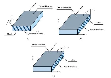
Figure 2:(a).Lamina of vertically reinforced 1-3 PZC;(b).Lamina of 1–3 PZC where the piezoelectric fibers are coplanar with the vertical xz plane.;(c).Lamina of 1–3 PZC where the piezoelectric fibers are coplanar with the vertical yz plane.

Figure 3:Kinematics of deformation of the plate in the xz and yz planes.
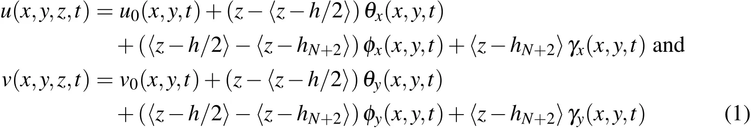
where,a function within the bracket〈〉represents the appropriate singularity functions such that the interface continuity of displacements between the substrate and the viscoelastic layer and between the viscoelastic layer and the constraining layer are satisfied.Since the objective of the present analysis is to control the flexural vibrations of the substrate plate and the magnitude of the transverse piezoelectric coefficient of the 1-3 PZC layer is much greater than that of the in-plane piezoelectric coefficients of the same,the transverse normal strain in the overall plate must be considered in the model.The transverse displacement w(x,y,z,t)at any point in the overall structure may be assumed to have quadratic variation with respect to z across their thicknesses and can be expressed as

in which w0refers to the transverse displacement at any point on the reference plane,θzand φzare the generalized displacements representing the gradient and the second order derivative of the transverse displacement in the overall structure with respect to the thickness coordinate(z).Such quadratic variation of transverse displacement also provides parabolic distribution of transverse shear stress across the thickness of the overall plate.For introducing geometric nonlinearity in the model,von Kármán type strain displacement relations are considered as follows:

For the ease of analysis,the generalized displacement variables are categorized into the following two generalized translational and rotational vectors:

The state of strain at any point in the overall system is divided into the bending strain vector{εb}and the out of plane shear strain vector{εs}as follows:

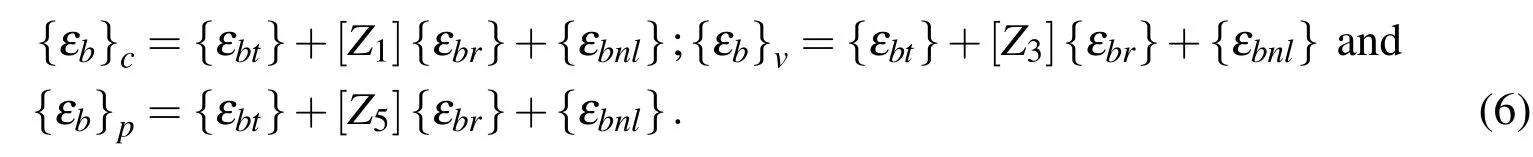
where εx,εy,εzare the normal strains along x,y and z directions,respectively,γxyis the in-plane shear strain and γxz,γyzare the transverse shear strains.By using the displacement fields(Eqs.(1)and(2))and the nonlinear strain displacement relations(Eq.(3)),the bending and shear strain vectors are obtained.The bending strain vectors{εb}c,{εb}vand{εb}pin the substrate composite plate,the constrained viscoelastic layer and the active constraining layer,respectively,can be expressed as
Similarly,the transverse shear strain vectors{εs}c,{εs}vand{εs}pin the substrate composite plate,the constrained viscoelastic layer and the active constraining layer,respectively,are given by:


Similar to the strain vectors given by Eq.(5),the state of stresses at any point in the overall plate are described by the following bending and transverse shear stress vectors:

where σx,σy,σzare the normal stresses along x,y and z directions,respectively,σxyis the in-plane shear stress and σxz,σyzare the transverse shear stresses.
2.1 Constitutive relation for the orthotropic material
As the laminated composite plate is made of several orthotropic layers with their principal material axes arbitrarily oriented with respect to the laminate coordinate system(xyz),the constitutive equations of each layer is transformed to the laminate coordinate system.Thus the stress–strain relations for the kth off-axis lamina with respect to the laminate coordinate system can be arranged in the context of the present formulation as follows:

2.2 Fractional order constitutive modeling of the viscoelastic material
The three-dimensional fractional order constitutive relations for the viscoelastic layer is derived using the four-parameter one-dimensional fractional order derivative constitutive relation.The one-dimensional fractional order derivative constitutive equation introduced by Bagley and Torvik(1983a)is given by

where σ and ε are the stress and the strain,respectively,E0and E∝are the relaxed and non-relaxed elastic moduli,τ is the relaxation time and α is the fractional order of the time derivative(0<α<1).Different definitions of fractional operator are available,out of which the best known are the Riemann-Liouville and Grünwald definition[Schmidt and Gaul(2002)].However,the Grünwald definition is easy to implement numerically[Schmidt and Gaul(2002)].The fractional operator for a function of time f(t),approximated by the Grünwald definition can be expressed as[Schmidt and Gaul(2002)]:
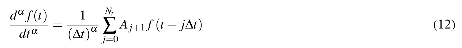
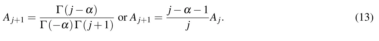
where Δt is the time increment for the numerical scheme and the upper limit Ntis the number of responses in memory and seems to be somewhat arbitrary,however it should be strictly less than the total number of time steps.Aj+1is the so called Grünwald constant and can be expressed by Gamma function(Γ)or recurrence formula as[Galucio,Deü,and Ohayon(2004)]:
Assuming constant Poisson’s ratio(ν)for the isotropic viscoelastic material and using Eq.(11),the normal strainsunder uniaxial loading alone along the x,y and z directions,respectively and the in-plane shear strainare given by

and similarly the transverse shear strainsandcan be expressed as

For an isotropic material,the three-dimensional normal strainsandalong x,yand z directions,respectively under three-dimensional state of stresses are given by
Thus using Eqs.(11),and(14)–(16),the three-dimensional constitutive relation for the viscoelastic material can be written as

where
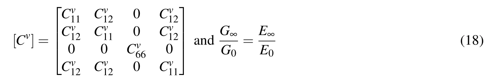
while the elastic coefficientsare presented in the Appendix.
At this juncture two anelastic strain functions can be introduced as follows:

where the anelastic bending strain functionand the anelastic transverse shear strain functionare given by

Substituting Eq.(19)into Eq.(17),the following equations are obtained which contain only one fractional derivative term.


Substituting the Grünwald definition of fractional derivative(Eq.(12))into Eq.(21)and noting that A1=1[Schmidt and Gaul(2002)],the following discretized general relations in the time domain are obtained at any(n+1)th time step:

where c is a dimensionless parameter given by
Finally,substituting the relations given in Eq.(22)into Eq.(19),the discretized forms of the constitutive relations of the viscoelastic material are obtained as follows:

2.3 Constitutive relation for the 1-3 piezo-composite(PZC)material
The constraining 1–3 PZC layer is considered to be subjected to the electric field Ezalong the z-direction only.Accordingly,the constitutive relations for the constraining layer of the ACLD treatment are given by[Ray and Pradhan(2006)]
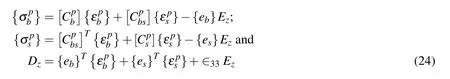

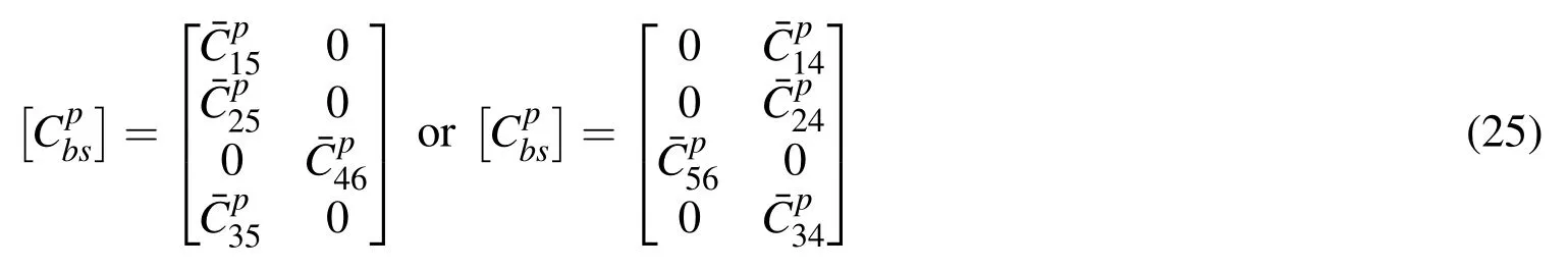
according as the piezoelectric fibers are coplanar with the vertical xz-or yz-plane.If the fibers of the PZC are coplanar with both the xz-and the yz-planes i.e.vertically reinforced,this coupling matrix becomes a null matrix.Also,the piezoelectric constant matrices{eb}and{es}appearing in Eq.(24)contain the following transformed effective piezoelectric coefficients of the 1–3 PZC:

The principle of virtual work is employed to derive the governing equations of the overall smart structure and can be expressed as
in which ρkis the mass density of the kth layer,{f}is the externally applied surface traction acting over a surface area A and Ωkrepresents the volume of the kth layer.It may be noted that the layer numbers N+1 and N+2 represent the viscoelastic layer and the piezoelectric layer,respectively.
3 Finite element formulation
The overall plate is discretized by eight-noded isoparametric quadrilateral elements.Following Eq.(4),the generalized displacement vectors,associated with the ith(i=1,2,3,...,8)node of the element can be written as

Thus the generalized displacement vector at any point within the element can be expressed in terms of the nodal generalized displacement vectorsndas follows:

in which

while Itand Irare the(3×3)and(8×8)identity matrices,respectively and niis the shape function of natural coordinates associated with the ith node.Making use of the relations given by Eqs.(6)to(8)and(29),the strain vectors at any point within the element can be expressed in terms of the nodal generalized displacement vectors as follows:

in which the nodal strain–displacement matrices[Btb],[Brb],[Bts],[Brs],[B1]and[B2]are given by

The sub-matrices of[Btbi],[Brbi],[Btsi]and[Brsi]as shown in Eq.(32)have been presented in the Appendix.Similarly the time dependent anelastic strain vectors associated with the viscoelastic layer can be expressed as

On substitution of Eqs.(31)and(33)into Eq.(27)and recognizing that Ez=−V/hpwith V being the applied voltage across the thickness of the piezoelectric layer,one can derive the following open-loop equations of motion of an element integrated with the ACLD treatment:


in which the elemental stiffness matrices associated with the bending strain vector are given by

and those associated with transverse shear strain vector are given by

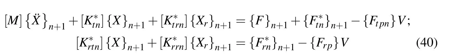
In the above matrices,aeand beindicate the length and the width of the element under consideration and the various rigidity matrices appearing in the above elemental stiffness matrices are given in the Appendix.Finally,the elemental equations of motion are assembled to obtain the open-loop global equations of motion of the overall structure integrated with the ACLD patch at any(n+1)th time step as follows:

where[M]is the global mass matrix,[Kttn],[Ktrn],[Krtn]and[Krr]are the global stiffness matrices;{¯Ftn}n+1and{¯Frn}n+1are the global viscelastic memory load;{Ftpn},{Frp}are the global electro-elastic coupling vectors;{X}and{Xr}are the global nodal generalized displacement vectors and{F}n+1is the global nodal force vector.
3.1 Computation of memory load due to the effect of viscoelastic material
Using the relation between the strain vectors and the anelastic strain vector,the relation between generalized global displacement vector and global anelastic displacement vector can be obtained as follows:

It may be mentioned here that the Grünwald coefficients(Aj)in Eq.(39)decreases with the increase in the value of j.Thus the response of the viscoelastic material at a particular time depends more strongly on the recent past history of the response than on the remote past history of the response.Therefore the Grünwald coefficients corresponding to the large value of j describe the fading memory of the viscoelastic layer and truncation of the Grünwald series after some value of j does not affect the response.Substituting Eq.(39)in Eq.(38),the open-loop global equations of motion of the overall structure is obtained in time domain as follows:


4 Closed loop model
For activating the patches of the ACLD treatment with a control voltage,a simple negative velocity feedback control law has been implemented.According to this law,the control voltage for each patch at any(n+1)th time step can be expressed in terms of the derivatives of the global nodal degrees of freedom as follows:


where the active damping matrix[Cn],the stiffness matrix[Kn]and the load vector due to the viscoelastic effect denoted byare given by
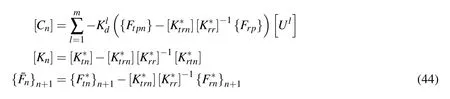
with m being the number of ACLD patches.
5 Validation of the model
The boundary conditions used for computing the numerical results are presented in Table 1.A MATLAB®code is developed using the finite element model formulated in the previous section.In order to verify the validity of the present finiteelement model,three examples are selected from the literature.For solving the nonlinear algebraic equations given in Eq.(43)an iterative method is required and for the present analysis direct iteration method is used.The first example is concerned about validating the direct iteration method where the nonlinear bending of a square simply-supported(SS1),orthotropic plate(aspect ratio a/h=10)made of high modulus glass-epoxy fiber-reinforced material integrated with the inactive ACLD patch of negligible thickness is first computed by the present model and subsequently,compared with the existing result[Reddy(2004)]of the identical plate without integrated with the patch as shown Fig.4.The following material properties are considered[Reddy(2004)].

Table 1:Various boundary conditions used in the finite element model.


Figure 4: Nonlinear load-deflection curve for simply-supported orthotropic square plate under uniform load.

Figure 5: Comparison of nonlinear transient response at the center of the simply-supported(SS1)(0°/90°/90°/0°)symmetric square cross ply plate.
The nondimensional load parameter shown in Fig.4 is given bywhere q0is the uniformly distributed load all over the plate.It may be observed that the load-deflection curve displayed in Fig.4 indicates that the present result matches very accurately with that of the Reddy(2004)validating the present finite element model and the direct iteration method for solving nonlinear equations.
The next analysis is performed on a four layer symmetric square cross-ply(0°/90°/90°/0°)plate integrated with the inactive ACLD patch of negligible thickness to compute the nonlinear transient response using the Newmark beta method under uniform step load with an intensity of 1 N/mm2[Chen,Dawe,and Wang(2000)].Material properties are considered as given in Eq.(45)while the geometric properties are used as a=b=250 mm and h=5 mm with each layer having equal thickness[Chen,Dawe,and Wang(2000)].The present results are compared with the response presented by Chen,Dawe,and Wang(2000)in Fig.5 for the same plate without the ACLD patch.The results computed using the present model matches very closely with that of the Chen,Dawe,and Wang(2000)proving the accuracy of the implementation of the numerical integration method.
Finally,a viscoelastic simply-supported beam[Galucio,Deü,and Ohayon(2004)]is chosen to validate the proposed three-dimensional constitutive relation for the viscoelastic material using the FDM.To compute the linear transient transverse vibration of the viscoelastic beam,the structure in Fig.1 is first modified.The ACLD patch is extended over the whole top surface of the substrate plate and subsequently the present model is reduced to a beam considering the geometrical parameters and the material properties same as that of the beam considered by Galucio,Deü,and Ohayon(2004).The following geometric data is then adopted following Galucio,Deü,and Ohayon(2004),a=10 m,b=2 m,hv=0.5 m while negligible thicknesses of the substrate plate(h)and the 1–3 PZC layer(hp)are considered.The viscoelastic material properties[Galucio,Deü,and Ohayon(2004)]are ρ =500 kg/m3,ν =0.3,E0=19.6 MPa,E∞=98 MPa,τ=2.24 sec and α =0.75.The shear correction factor used for this analysis is assumed as[Galucio,Deü,and Ohayon(2004)]kc=10(1+ν)/(12+11ν).The time dependent transverse displacement of the center of the beam under uniform step load of 10 N/m applied all over the beam is compared with that computed by Galucio,Deü,and Ohayon(2004)as shown in Fig.6.It may be observed that the two response curves match excellently with each other.This con firms that the present three-dimensional constitutive relation for the viscoelastic material using the FDM is highly accurate and can be successfully implemented for three-dimensional analysis of passive and active constrained layer damping of geometrically nonlinear smart composite plates.
6 Results and discussion
In this section,the numerical results obtained by the finite element model derived in Section 4 have been presented.Numerical results are presented considering different stacking sequences and boundary conditions(Table 1)for the laminated square substrate plates integrated with a patch of ACLD treatment attached at the center of the top surface of the substrate plates.The length and the width of the patch are considered to be 50%of the length and the width of the substrate plates,respectively.PZT-5H/spur epoxy composite with 60%piezoelectric fiber volume fraction has been considered for the material of the constraining layer of the ACLD treatment.The elastic and the piezoelectric properties and the density of this constraining layer are[Ray and Pradhan(2007)]:
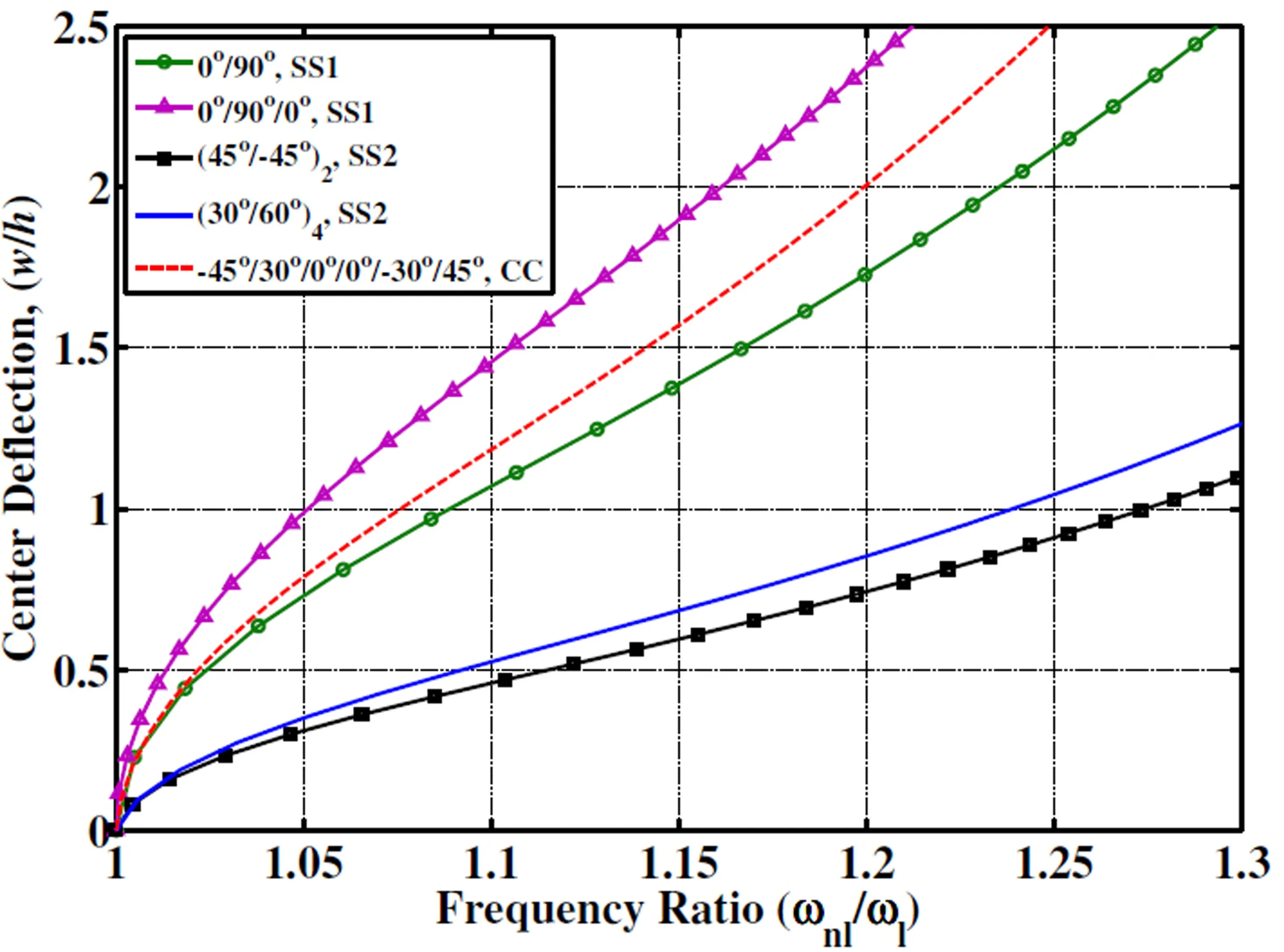
Figure 7:Backbone curves for square plates with different boundary conditions under uniform load with the ACLD patch.

The thickness of the 1-3 PZC layer is considered as hp=600µm for all the analyses.The viscoelastic material is chosen as ISD112 which is characterized by the following material properties[Galucio,Deü,and Ohayon(2005)]:

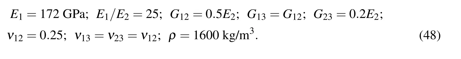
The thickness of the constrained viscoelastic layer is chosen as hv=250µm.The material of the orthotropic layers of the substrate plates is a graphite/epoxy composite and its material properties are[Reddy(2004)]:
The length(a)and the width(b)of the substrate plates with SS1 and SS2 type boundary conditions are considered as a=b=0.4 m while for the CC type boundary condition the same was assumed as a=b=0.5 m.In all the examples the overall thickness of the substrate plates is taken as h=3 mm and each orthotropic layer of a substrate plate is considered to be of equal thickness.The shear correction factor is chosen to be kc=5/6.A uniformly distributed load is suddenly applied all over the plate to analyze the control of the transient vibration.The intensity of the applied load is decided from the backbone curve(Fig.7)of the corresponding substrate laminated plate and to incorporate sufficient nonlinearity in the present analyses,the frequency ratio(ωnl/ωl)is kept more than 1.1.The control voltage supplied to the ACLD patch is negatively proportional to the velocity of the point at the center˙w(a/2,b/2,h/2)of the plate.Depending on the applied load,the control gain is chosen arbitrarily such that the value of the control voltage is nominal and the vibrations are also under control.
It is already mentioned earlier that the upper limit of the Grünwald series(Nt)is the number of responses in memory and is somewhat arbitrary but must be less than the number of time steps.Thus at this juncture it is crucial to find out whether an approximate truncated value of Ntcan be obtained so that sufficiently accurate computation of the memory load is possible without losing much memory information and the damping property of the viscoelastic material with elapsed time.Two cases are examined in this regard.First a(0°/90°)antisymmetric square cross ply substrate plate with SS1 type boundary condition is selected to observe the effect of truncated value of Ntunder 1.6 kN/m2uniform load when the plate is under PCLD treatment.In the next example the same plate is analyzed when it is under ACLD treatment(Kd=240).Comparison of responses for Nt=5,10 and 2000 are presented in Figs.8 and 9 when the plate is under PCLD and ACLD treatment(ψ =0°),respectively.It may be observed from Figs.8 and 9 that obtained responses using less number of terms in the Grünwald series negligibly differ from the actual responses when all terms in the Grünwald series is considered.This can be justified from the definition of Grünwald constant given in Eq.(13).It may be noted that it depends on the fractional order(α)of the derivative which is constant for a particular viscoelastic material and thus increasing the number of Grünwald terms rapidly decreases the corresponding Grünwald constant.This substantiates the fading memory effect of the viscoelastic material.
For presenting the numerical results all the memory terms in the Grünwald series are considered while calculating viscoelastic memory load.The efficiency of the obliquely reinforced 1–3 PZC layer for controlling the vibrations of the plates is analyzed by measuring the control authority of the ACLD patch for different piezoelectric fiber orientation angle(ψ)in the vertical xz or yz planes.To measure the percentage reduction in the amplitude of vibration at the center of the plate,a performance index(Id)is defined as follows:

Figure 9:Effect of truncation of Nt for transient response at the center of the simply-supported(SS1)(0°/90°)antisymmetric square cross ply plate under ACLD treatment for Kd=240 and α=0.7915.

Figure 10:Performance index of the ACLD patch for different piezoelectric fiber orientation angle(ψ)of the 1–3 PZC layer in the xz plane for controlling vibrations of square plates with different boundary conditions under uniform load.

Figure 11:Transient responses of a simply supported(0°/90°/0°)symmetric square cross-ply plate undergoing PCLD and ACLD.

where a1and a10are the amplitudes of vibration at the 1stpeak and the 10thpeak.For a maximum control voltage of 250 V,the variation of the performance index(Id)with the piezoelectric fiber orientation angle(ψ)in the xz plane is presented in Fig.10 for different substrate plates and boundary conditions.Similar results can be obtained(not presented here)when the piezoelectric fiber orientation angle(ψ)is varied in the vertical yz plane.It may be noted that the ACLD patch provides maximum control authority when vertically reinforced(ψ =0°)1–3 PZC is used.

Figure 12: Control voltage required for the ACLD of a simply supported(0°/90°/0°)symmetric square cross-ply plate undergoing ACLD.
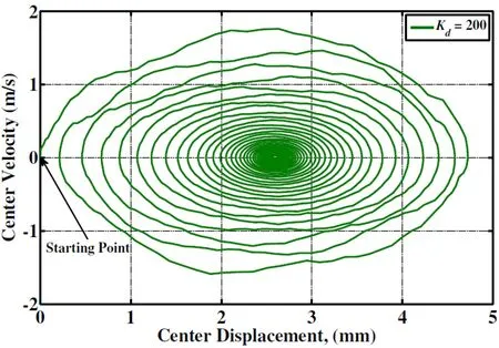
Figure 13:Phase plot of a simply supported(0°/90°/0°)symmetric cross-ply plate undergoing ACLD.
Figure 11 illustrates the transient response of a(0°/90°/0°)symmetric square cross ply plate under 3.8 kN/m2uniform load with SS1 type boundary condition.The responses displayed in the figure correspond to the cases when the patch is passive(Kd=0)and active(Kd/=0)while the piezoelectric fiber orientation angle(ψ)is considered to be 0°.The figure clearly reveals that the constraining layer made of vertically reinforced 1–3 PZC material significantly attenuates the amplitude of vibrations,enhancing the damping characteristics of the laminated composite plates over the passive damping(Kd=0).The control voltages corresponding to the different gain values are quite nominal as shown in Fig.12 for controlling the vibration.Since the control voltage is proportional to the velocity of a point of the plate,the illustration of the control voltages in Fig.12 also indicate that at any point of the overall plate,the velocity also decays with time.The phase plot presented in Fig.13,corroborates the same indicating the stability of the plate.
The transient responses of simply-supported(SS2)antisymmetric angle ply plate with four layers(45°/−45°/45°/−45°)under 3.1 kN/m2uniform load and angle ply plate with eight layers(30°/60°)4under 2.3 kN/m2uniform load are presented in Figs.14 and 15 for both passive(Kd=0)and active(Kd/=0)control,respectively.In this case also the piezoelectric fiber orientation angle(ψ)is considered as 0°to obtain maximum control authority.Figs.16 and 17 demonstrate the cor-responding control voltages required to achieve the active responses presented in Figures 14 and 15,respectively.It may be observed from these figures that the ACLD patch also effectively controls the vibrations of the angle ply plates enhancing the damping characteristics with nominal control voltage.In the final example similar analyzes have been performed on a clamped-clamped(CC)laminated plate having six generally orthotropic layers(−45°/30°/0°/0°/−30°/45°)and the responses under 4.8 kN/m2uniform load are depicted in Fig.18 for both passive(Kd=0)and active(Kd/=0)control(ψ =0°).From Fig.18 similar conclusions can be drawn that the ACLD treatment has significantly improved the control of the CC plate over the PCLD treatment.Also the required control voltage(Fig.19)is nominal.

Figure 14:Transient responses of a simply supported(45°/−45°/45°/−45°)antisymmetric angle-ply plate undergoing PCLD and ACLD.

Figure 15:Transient responses of a simply supported(30°/60°)4angle-ply plate undergoing PCLD and ACLD.

Figure 16:Control voltage required for the ACLD of a simply supported(45°/−45°/45°/−45°)antisymmetric angleply plate undergoing ACLD.

Figure 17: Control voltage required for the ACLD of a simply supported(30°/60°)4angle-ply plate undergoing ACLD.

Figure 18: Transient responses of a clamped-clamped (−45°/30°/0°/0°/−30°/45°)symmetric angle-ply plate undergoing PCLD and ACLD.

Figure 19: Control voltage required for the ACLD of a clamped-clamped(−45°/30°/0°/0°/−30°/45°) angle-ply plate undergoing ACLD.
7 Conclusions
A three-dimensional finite element analysis has been carried out to investigate the performance of the patch of the ACLD treatment for controlling geometrically nonlinear vibrations of orthotropic laminated composite plates.The constraining layer of the ACLD patch is considered to be made of the vertically/obliquely reinforced 1–3 PZC.Existing one-dimensional form of the fractional order derivative constitutive model of the viscoelastic material has been augmented to derive a threedimensional fractional order derivative model(FDM)of the constrained viscoelastic layer.The kinematics of deformations of the whole structure is assumed to be based on the FSDT and von Kármán type strain displacement relation has been used to account for the geometric nonlinearity.A simple velocity feedback control law is used to introduce the active damping.Validations for both FSDT and FDM are presented.Examples are presented to determine the effect of the number of memory terms in the Grünwald series(Nt),so that accurate dynamic response can be obtained with effective implementation of the FDM.Further analyses are performed on the laminated plates with symmetric/antisymmetric cross-ply and antisymmetric angle-ply and a general layup laminate with different boundary conditions for evaluating the numerical results.The numerical results for controlled responses reveal that the ACLD treatment significantly improves the active damping characteristics of the structure over the PCLD treatment of the same for suppressing their geometrically nonlinear transient vibrations.The present investigation suggests that the fractional order derivative model of viscoelastic layer is a computationally efficient model for time domain analysis of the ACLD of geometrically nonlinear vibrations of laminated composite plates.
Bagley,R.L.;Torvik,P.J.(1983a):A theoretical basis for the application of fractional calculus to viscoelasticity.Journal of Rheology,vol.27,no.3,pp.201–210.
Bagley,R.L.;Torvik,P.J.(1983b):Fractional calculus–a different approach to the analysis of viscoelastically damped structures.AIAA Journal,vol.21,no.5,pp.741–748.
Bagley,R.L.;Torvik,P.J.(1985):Fractional calculus in the transient analysis of viscoelatically damped structure.AIAA Journal,vol.23,no.3,pp.201–210.
Balamurugan,V.;Narayanan,S.(2002):Finite element formulation and active vibration control study on beams using smart constrained layer damping(SCLD)treatment.Journal of Sound and Vibration,vol.249,no.2,pp.227–250.
Baz,A.M.;Ro,J.(1994):Concept and performance of active constrained layer damping treatments.S V Sound and Vibration,vol.28,no.3,pp.18–21.
Baz,A.;Ro,J.(1995):Performance characteristics of active constrained layer damping.Shock and Vibration,vol.2,no.1,pp.33–42.
Biswas,D.;Ray,M.C.(2013):Active constrained layer damping of geometrically nonlinear vibration of rotating composite beams using 1–3 piezoelectric composite.International Journal of Mechanics and Materials in Design,vol.9,no.1,pp.83–104.
Chen,J.;Dawe,D.J.;Wang,S.(2000):Nonlinear transient analysis of rectangular composite laminated plates.Composite Structures,vol.49,no.2,pp.129–139.
Datta,P.;Ray,M.C.(2015):Finite element analysis of laminated composite plates using zeroth-order shear deformation theory.International Journal of Mechanics and Materials in Design,DOI 10.1007/s10999-015-9307-0.
Dong,L.;El-Gizawy,A.S.;Juhany,K.A.;Atluri,S.N.(2014a):A simple locking-alleviated 3D 8-node mixed-collocation c0 finite element with overintegration,for functionally-graded and laminated thick-section plates and shells,with&without z-pins.CMC:Computers Materials and Continua,vol.41,no.3,pp.163–192.
Dong,L.;El-Gizawy,A.S.;Juhany,K.A.;Atluri,S.N.(2014b):A simple locking-alleviated 4-node mixed-collocation finite element with over-integration,for homogeneous or functionally-graded or thick-section laminated composite beams.CMC:Computers,Materials&Continua,vol.40,no.1,pp.49–77.
Galucio,A.C.;Deü,J.F.;Ohayon,R.(2005):A fractional derivative viscoelastic model for hybrid active-passive damping treatments in time domain-application to sandwich beams.Journal of Intelligent Material Systems and Structures,vol.16,no.1,pp.33–45.
Galucio,A.C.;Deü,J.F.;Ohayon,R.(2004):Finite element formulation of viscoelastic sandwich beams using fractional derivative operators.Computational Mechanics,vol.33,no.4,pp.282–291.
Gentilman,R.;Fiore,D.;Houston,B.;Corsaro,R.(1999):Piezocomposites for active surface control(No.MIS-111).Materials Systems Inc.,Littleton MA.
Golla,D.F.;Hughes,P.C.(1985):Dynamics of viscoelastic structures–a timedomain, finite element formulation.Journal of Applied Mechanics,Transactions ASME,vol.52,no.4,pp.897–906.
Ha,S.K.;Keilers,C.;Chang,F.K.(1992):Finite element analysis of composite structures containing distributed piezoceramic sensors and actuators.AIAA Journal,vol.30,no.3,pp.772–780.
Hwang,W.S.;Park,H.C.(1993):Finite element modeling of piezoelectric sensors and actuators.AIAA Journal,vol.31,no.5,pp.930–937.
Kanasogi,R.M.;Ray,M.C.(2013):Control of geometrically nonlinear vibrations of skew laminated composite plates using skew or rectangular 1–3 piezoelectric patches.Smart Materials and Structures,vol.22,no.10.
Kanasogi,R.M.;Ray,M.C.(2015):Performance of Skew or Rectangular S-mart Patches for Active Damping of Nonlinear Vibrations of Skew Doubly Curved Laminated Composite Shells.International Journal of Mechanics and Materials in Design,vol.11,no.2,pp.173–202.
Kattimani,S.C.;Ray,M.C.(2014a):Active control of large amplitude vibrations of smart magneto-electro-elastic doubly curved shells.International Journal of Mechanics and Materials in Design,vol.10,no.4,pp.351–378.
Kattimani,S.C.;Ray,M.C.(2014b):Smart Damping of Geometrically Nonlinear Vibrations of Magneto-Electro-Elastic Plates.Composite Structures,vol.114,no.1,pp.51–63.
Kumar,R.S.;Ray,M.C.(2013):Active control of geometrically nonlinear vibrations of doubly curved smart sandwich shells using 1–3 piezoelectric composites.Composite Structures,vol.105,pp.173–187.
Kundalwal,S.I.;Kumar,R.S.;Ray,M.C.(2013):Smart damping of laminated fuzzy fiber reinforced composite shells using 1–3 piezoelectric composites.Smart Mater.Struct.,vol.22,Article ID 105001.
Lesieutre,G.A.;Bianchini,E.(1995):Time domain modeling of linear viscoelasticity using anelastic displacement fields.Journal of Vibration and Acoustics,Transactions of the ASME,vol.117,no.4,pp.424–430.
Lesieutre,G.A.;Mingori,D.L.(1990):Finite element modeling of frequencydependent material damping using augmenting thermodynamic fields.Journal of Guidance,Control,and Dynamics,vol.13,no.6,pp.1040–1050.
Lo,K.H.;Christensen,R.M.;Wu,E.M.(1977):A high-order theory of plate deformation,part 2:laminated plates.Journal of Applied Mechanics,Transactions ASME,vol.44,no.4,pp.669–676.
McTavish,D.J.;Hughes,P.C.(1993):Modeling of linear viscoelastic space structures.Journal of vibration,acoustics,stress,and reliability in design,vol.115,no.1,pp.103–110.
Panda,S.;Ray,M.C.(2009a):Control of nonlinear vibrations of functionally graded plates using 1-3 piezoelectric composite.AIAA Journal,vol.47,no.6,pp.1421–1434.
Panda,S.;Ray,M.C.(2009b):Active control of geometrically nonlinear vibrations of functionally graded laminated composite plates using piezoelectric fiber reinforced composites.Journal of Sound and Vibration,vol.325,no.1,pp.186–205.
Panda,S.;Ray,M.C.(2012):Active damping of nonlinear vibrations of functionally graded laminated composite plates using vertically/obliquely reinforced 1–3 piezoelectric composite.Journal of Vibration and Acoustics,Transactions of the ASME,vol.134,no.2.
Ray,M.C.(1998):Closed-form solution for optimal control of laminated plate.Computers and Structures,vol.69,no.2,pp.283–290.
Ray,M.C.(2003):Zeroth-order shear deformation theory for laminated composite plates.Journal of Applied Mechanics,Transactions ASME,vol.70,no.3,pp.374–380.
Ray,M.C.(2007):Smart damping of laminated thin cylindrical panels using piezoelectric fiber reinforced composites.International Journal of Solids and Structures,vol.44,no.2,pp.587–602.
Ray,M.C.;Mallik,N.(2005):Performance of smart damping treatment using piezoelectric fiber-reinforced composites.AIAA Journal,vol.43,no.1,pp.184–193.
Ray,M.C.;Pradhan,A.K.(2006):The performance of vertically reinforced 1–3 piezoelectric composites in active damping of smart structures.Smart Materials and Structures,vol.15,no.2,pp.631–641.
Ray,M.C.;Pradhan,A.K.(2007):On the use of vertically reinforced 1–3 piezoelectric composites for hybrid damping of laminated composite plates.Mechanics of Advanced Materials and Structures,vol.14,no.4,pp.245–261.
Ray,M.C.;Batra R.C.(2007):A single-walled carbon nanotube reinforced 1–3 piezoelectric composite for active control of smart structures.Smart Materials and Structures vo.16,no.5,pp.1936–1947.
Ray,M.C.;Shivakumar,J.(2009):Active constrained layer damping of geometrically nonlinear transient vibrations of composite plates using piezoelectric fiber-reinforced composite.Thin-Walled Structures,vol.47,no.2,pp.178–189.
Ray,M.C.;Dong,L.;Atluri,S.N.(2015):Simple efficient smart finite elements for the analysis of smart composite beams,CMC:Computers Materials and Continua,vol.47,no.3,pp.143–177.
Reddy,J.N.(2004):Mechanics of laminated composite plates and shells:theory and analysis,CRC Press,Boca Raton,FL.
Sarangi,S.K.;Ray,M.C.(2010):Smart damping of geometrically nonlinear vibrations of laminated composite beams using vertically reinforced 1–3 piezoelectric composites.Smart Materials and Structures,vol.19,no.7.
Schmidt,A.;Gaul,L.(2002):Finite element formulation of viscoelastic constitutive equations using fractional time derivatives.Nonlinear Dynamics,vol.29,no.1–4,pp.37–55.
Shen,I.Y.(1994):Bending-vibration control of composite and isotropic plates through intelligent constrained-layer treatments.Smart Materials and Structures,vol.3,no.1,pp.59–70.
Stanway,R.;Rongong,J.A.;Sims,N.D.(2003):Active constrained-layer damping:a state-of-the-art review.Proceedings of the Institution of Mechanical Engineers.Part I:Journal of Systems and Control Engineering,vol.217,no.6,pp.437–456.
Yi,S.;Ling,S.F.;Ying,M.(1998):Finite element analysis of composite structures with smart constrained layer damping.Advances in Engineering Software,vol.29,no.3–6,pp.265–271.
Yi,S.;Sze,K.Y.(2000):A finite element formulation for composite laminates with smart constrained layer damping.Advances in Engineering Software,vol.31,no.8,pp.529–537.
1Mechanical Engineering Department,Indian Institute of Technology,Kharagpur 721302,India
Appendix
The transformed elastic coefficient matrices in equation(10)have the following form.

In Eq.(18)the elastic coefficientsfor the viscoelastic material can be written as:


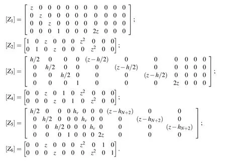
The sub-matrices of[Btbi],[Brbi],[Btsi]and[Brsi]as shown in Eq.(32)can be explicitly written as:


The various rigidity matrices appearing in Eqs.(36)and(37)are given by


