Time-Dependent J-Integral Solution for Semi-elliptical Surface Crack in HDPE
2015-12-12BendoubaDjebliAidBenseddiqandBenguediab
M.Bendouba,A.Djebli,A.Aid,N.Benseddiqand M.Benguediab
Time-Dependent J-Integral Solution for Semi-elliptical Surface Crack in HDPE
M.Bendouba1,A.Djebli1,A.Aid1,N.Benseddiq2and M.Benguediab3
This work focuses on a linear elastic analysis by the finite element method and the development of a shape function,commonly known as geometrical correction factor,for the case of semi-elliptical crack in a cylindrical rod.We used the same shape function to analyze the behavior of the rod in the case of a viscoelastic medium materialized by a polymeric material such as HDPE.A linear viscoelastic model calibrated from a relaxation test was developed and implemented in Abaqus.Results showed a relatively good performance,compared with finite element method.
J-integral,Viscoelastic,HDPE.
1 Introduction
The ability to predict crack growth continues to be a major component of research for several structural materials.Multiple mechanisms may be responsible for crack initiation,nevertheless eventually dominant fatigue cracks evolve into surface cracks,which often have a semi-elliptical shape[Findley,(2007)]
Cylindrical components such as pipes,pins,reinforcement wires and shafts are commonly used in engineering structures,where,under repeated or continued loading,cracks may develop at the surface and grow across the section[Cai(2005)].Due to geometrical complexity,certain simplification had been made for the crack pro file;early attempts used a straight edge[Daoudet al.(1978);Bush(1981);Carpinteri(1992)]or a circular arc[Wilhemet al.(1982);Mackay and Alperin(1985);Daoud(1985);Forman and Shivakumar(1986);Raju and Newman(1986)]to idealize the crack front.These idealizations,although so close,are not exactly in agreement with experimental observations[Shin and Cai(2004)].Thus,the authors,through recent works,agree on this crack con figuration.Afterward,linear elastic fracture mechanics(LEFM)has been used to analyze stress intensity factors along the crack front for the case of Mode I loading.Recently,a solution of SIFs under mode III was proposed by Benhamenaet al.(2011)for two bonded functionally graded material,and recently,the solution for combined loading(bending,tension and torsion)was proposed[Danton,(2002)]. Apart from the metallic materials that have attracted abundant literature in this subject of research,the polymer materials,unfortunately,have not had their fair share of the subject,apart from works dealing with the subject in point of view elastic or elastoplastic material domain.However it is established that between this two domain,there is one area where the response of the material is substantially dependent on the speed of loading.Thus,unlike metallic materials,the mechanical properties of polymeric materials are indeed sensitive to many parameters,even under normal operating conditions,such as loading rate and temperature.In addition,physical,chemical and mechanical changes can occur in service,especially,when they are subjected to cyclic loading(crack growth)as considered by Hernándezet al.(2001)
Controlling these parameters,and predicting their long-term effects,helps to avoid design errors,and maintain the integrity of structures.For viscoelastic material,fracture toughness is assumed to be a material property function.As such,it is implicitly taken to depend on loading rate and temperature.In practice,this property function may be quantified using differents methods.Popular among these methods,the work of fracture,the critical energy release rate,the pseudo-elastic or viscoelastic J integral,and the more common critical J integral[Riyadh and Wafa(2006)]According to Danton(2002),it is unlikely that a single-parameter material function would suffice to fully characterize the fracture response of a real linear viscoelastic solid.In practice it is merely hoped that if geometric effects are removed from the test data,a test article and a cracked structural component will fail at the same value of the fracture parameter only if the corresponding failure times are also the same.
It is in this restricted sense that theJintegral at crack-growth initiation(Jc(t))is taken here as a measure of fracture resistance.
Many resent papers in fracture and fatigue analysis of complex 2D&3D solid structures and materials are presented[see,Dong and Atluri(2012);Dong and Atluri(2013)].The interest for this series of works is to explore the advantageous features of computational methods as modelling the complicated uncracked structures with simple FEMs,and model the crack-singularities by mathematical methods such as complex variables,special functions.
HDPE is a significant material,whose tensile creep is a suitable measure of its viscoelastic nature[Schapery(1984);Creus(1986)].It is used in the manufacturing of pipes for transporting fluids such as natural gas and water under relatively high permanent loads,for this reason it is necessary to develop simple tools for engineers to optimize the design of all polymer components,while compromising the safety and cost.When linear viscoelasticity theory is applied to the analysis of the traction problem for a cracked body,the correspondence principle indicates that stresses remain constant in time[Knauss(1973);Williams(1984);Masuero and Creus(1993)].Thus,when aKstress intensity criterion for crack growth is applied,no deferred effect appears to be possible.On the other hand,experimental results[Williams(1984);Ismail et al.(2012)]indicate that cracks in viscoelastic materials grow under constant loads proficiently beneath the elastic fracture load level.In this study,we analyze the applicability of the concept of the normalized stress intensity factor,in the case of a viscoelastic material behavior.For that purpose, finite element analysis is performed to analyze the behavior of a cylindrical rod having a semi elliptical crack,by analyzing the evolution of stress intensities along the crack front.The elastic mechanical properties such as Young’s modulus(E)and Poisson’s ratio(ν)are taken arbitrarily in order to calculate the normalizedSIF,and developing its analytical function under the ModeIcase loading.Thereafter,we checked the validity of this function for the calculation of theJintegral in the case of viscoelastic response.Therefore,An expression of the normalizedSIFs F(a/c,a/D,x/h=0)to the deepest point is obtained.The second purpose of this paper is an analysis of visco-Elastic fracture behavior of HDPE rod loaded in tension,by studying theJintegral(in sense ofG(t))evolution with time.The results have led to the formulation of analyticalJ(t)relationship that involve the normalizedSIFs(F(a/c,a/D,x/h=0))that has been developed in the first section and time-dependent modulusE(t).The analytical relationship obtained describes the evolution of the energy release rate with time,and gives an advantage for quick and simple calculation of the rupture parameters,such as theJintegral.
2 Material and method
2.1 Geometrical model
This study presents a three dimensional finite element analysis using Abaqus commercial[Abaqus(2009]code for semi-elliptical surface cracks in rod.The rod was subjected to remote tension load.The ratio of crack depth to crack length(a/c)ranged from 0.1 to 1,the ratio of crack depth to rod diameter(a/D)ranged from 0.05 to 0.45.Figure 1 presents the geometrical model used in this study.
2.2 Material Model
As has been argued above,this analysis highlights the point on the independence of the normalizedSIF Fwith respect to the elastic properties(E,v)intrinsic to

Figure 1:Schematic illustration for surface cracked and definition of an arbitrary crack shape.
the material,For this reason,the mechanical properties used in the calculation ofFare chosen arbitrarily,E=207GPaand ν=0.3,as values of Young’s modulus and Poisson’s ratio,respectively.Otherwise,in the second section of this paper,the mechanical model used is linear viscoelastic.The material of interest is a Polyethylene HDPE characterized at different strain rates by Riadhet al.(2006),the authors have con firmed,following an experimental analysis using creep and relaxation tests at room temperature,the linear viscoelastic nature of the polymer of interest in the field of small deformations.However,static mechanical properties for various strain rates are shown in Tab.1[Riadhet al.(2006)]
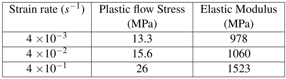
Table 1:Tensile mechanical properties of HDPE under different strain rates[Riadh et al.(2006)].
Figure 2 illustrates the superposition of the relaxation modulus for different levels of imposed strains that assumes a linear viscoelastic behavior at room temperature[Riadhet al.,(2006)]

Figure 2:Experimental tensile stress relaxation modulus E(t)of HDPE versus time for different applied strain levels[Riadh et al.(2006].
2.3 Finite element modeling
Finite element model is developed using Abaqus,A re fined mesh has been created in the area that surrounds the crack front,with using of 20 nodes iso-parametric quadratic brick elements.The square root singularity of stress and strain fields is modeled by shifting the mid-point nodes to the quarter point location around the crack line region This fact is made possible by choosing wedge elements with 15 nodes surrounding the crack tip(Figure 3).

Figure 3:Detailed modeling of the singularity in the region of the crack line.
The geometry of the surface crack is completely de fined by the size ratioa/Dand the crack shape ratioa/c(Figure 1),whereD,aandcare,respectively,the diameter of the rod,the crack depth(minor radius of the ellipse)and the major radius of the ellipse.a/cis ranged between 0.1 to 0.9,while,a/Dis taken between 0.05 and 0.45,with different increments to encompass the majority of shapes and sizes as possible similar works as Duboiset al.,(2001)the Warbyet al.,(1992)A typical finite element model is shown in Figure 4

Figure 4:Typical Finite element model.
We have applied uniaxial tensile load at the free end of the rod,the other end(the crack plane minus its surface)is fixed with respect to displacement along the axis of the rod as rotations.For reasons of symmetry of loading and geometry,we used a quarter of the rod to minimize the cost in computation time and memory space allocated.The rods length is taken toH=200mm.since,as it is illustrated in Figure 5,the value ofJis independent of this latter,however,Raju and Newman(1986)require a length sufficiently large as a condition of applicability of their approach;the diameterDis fixed toD=20 mm.
2.4 Evaluation of the rupture parameters
2.4.1Normalized SIF F
It is recognized in linear fracture mechanics that stress intensity factor is obtained by the following relation:

The elasticFEresults displays the elastic component ofJintegral,the stress intensity factor for modeIcondition can be extracted as:


Figure 5:Elastic FE results of J integral along the crack front for different rod lengths.
Where,the subscriptIindicates the mode one(crack opening),E′=Efor plane stress condition andE′=E?1-ν2for plane strain condition.
A normalizedSIF(shape function),F,can be de fined as:

Fvalues will be evaluated using the results of the J-integral obtained by numerical simulation,just the deepest pointAwill be discussed here,yet a full analysis of the results allows extending the current approach to all points on the line of the crack front with restrictions on the outer point where the singularity is poorly de fined[Danton(2002)]
3 Analysis of J
Through the results obtained in this study,we found a fact that different contours integrals yield almost equal values ofJ(except the first contour),which con firms one of the properties ofJthrough our calculations;we have chosen the values of the last contour in the analysis.Figure 6 illustrate three trends ofJalong the crack front,which provides information on the intensity distribution of stresses.

Figure 6:FE results of J for various crack parameters a)a/D=0.2,b)a/D=0.333.
The first tendency is that obtained for aspect ratios(0.1≤a/c≤0.5),we note thatJis maximum at the deepest point of the crack(see Figure 1)and it is a minimum in the surface point of the crack,The second trend is observed for the aspect ratios(0.6,0.7),whereJshows relative stability along the crack front,for aspect ratios greater than 0.7,the trend is reversed andJbecomes maximum at the surface point and it decreases to the minimum value at the deepest point.The evolution ofJshown in Figure 6 is qualitatively reproduced for all size ratios(a/D).Figure 7 shows the results ofJas a function of the position on the crack front for a size ratioa/D=0.133,and different shape ratios.The three trends ofJare clearly illustrated.These results yield an idea on the crack propagation.Now,if the initial crack con figuration where(a/c)is greater than 0.7 is assumed,crack starts propagating at the outside point.The parameter(c)is expanded,therefore,(a/c)decreases and the crack adopts a larger con figuration,at this stage,the depth(a)is constant and remains constant until(a/c)is equal to or less than 0.5,Jwill now be maximum at the deepest point.It is noted here that the critical value ofJis reached first and therefore(a)increases.The propagation process is reversed to the depth direction.The crack has a larger size and will find its original shape.

Figure 7:The effect of aspect ratio(a/c)on the value of J along the crack front for a size ratio a/D=0.133.
4 Results
4.1 Normalized SIF(F)formulation
Now,we present the expression of the NormalizedSIF(F)to be used in the analytical formulation ofJin the section dealing with the linear viscoelastic behavior of HDPE.
The results obtained by theFEMallowed us to calculate(F)for all shape and size ratios,and after smoothing the results,we established an expression that gives(F)as a function of(a/canda/D)Attention is pointed on the deepest pointA(x/h=0,Figure 1).Thus,(x/h)will not be taken as a parameter in the function.The results are validated by comparison with those collected from literature.Figure 8 show the variation ofFas a function with the respect of the aspect ratios for different size ratios.A polynomial fit of results in Figure 9 provides a variety of coefficientbi(bi=f(a/D)).

Figure 8:Variation of F as a function of aspect ratios for different size ratios.

Figure 9:Variation of bi(i=0,1,2,3)coefficient with respect to size ration a/D.
We observe that,indeed,Fdecreases with increasing(a/c)and it increases with increasing(a/D).The combination of data and the curves fitting resulted in an expression of(F)as follows:

The values ofBijare summarized in Tab.2
The results summarized in Figure 10 show confrontations of our results with those of Shin and Cai,(2004).In the works of Warbyet al.(1992)and those of Raju and Newman(1986),we note here that we used con figurations of cracks similar to shin and Cai(2004)However,Raju and Newman(1986)de fine the parametercas the length intersection of the crack surface with the outer surface of the rod.Results ofFexpression obtained in this work are in agreement with the results obtained by Shin and Cai(2004)for all aspect ratios.Deviations are observed from the results Raju and Newman(1986),especially for large size ratios.This fact can beexplained by the difference between the definition of crack parameterc,therefore,if we observe Figure 10(b),where(a/c)=0.8,the difference between the results decreases significantly.

Table 2:BijFactors of Eq.4.

Figure 10:Variation of F with respect to a/D,a)Comparison of present results for a/c=0.6,b)a/c=0.8,c)a/c=1.
Exactly,at this con figuration,we have observed that the two definitions ofccoincide,which explain the consistency of theFvalues.For aspect ratios less than 0.8,our results are below those of Raju and Newman(1986)(Figure 10(a)),the difference becomes greater pronounced by increasing the size ratios(a/D),in the other hand,fora/cgreater than 0.8,our results are above those of Raju and Newman(1986)(Figure 10(c)).These observations are illuminated by Figure 11 that con firms the observation made for the consistency of the results with those of Shin and Cai(2004).We clearly observe that the curves intersect at the point(a/c=0.8),where we observe almost the same value ofF.

Figure 11:Variation of F with respect to a/c,comparison of the present results for;a)a/c=0.6,b)a/c=0.8 and c)a/c=1.
4.2 Correspondence principle for viscoelastic material.

Figure 12:Evolution of J with time along the crack front for a/D=0.35 and a/c=0.2.

Figure 13:Evolution of J with time along the crack front for a/D=0.35 and a/c=0.9.
Polymeric materials such as HDPE are increasingly used in engineering;these viscoelastic materials are time-dependent.That is,the viscoelastic mechanical behavior problems are dependent on both the current state and the entire history[Riadh and Wafa(2006)]This material is a typical mesoscopic response of semicrystalline polymers,see Tomita and Uchida(2005).Generally,the stress level is relatively low and loading time is not long,so the mechanical properties of numerous viscoelastic materials are usually modeled as linear viscoelastic materials[Williams(1984)]For linear viscoelasticity,the determination of solutions is to invoke the numerical inversion of Laplace transform[Marques and Creus(2012)].FEM,as commonly computational methods,has been used to investigate viscoelastic problems[Park and Schapery(1999);Stavros and Jiangwei(2008)].So,for service loading conditions,and with the assumption that the material is homogeneous and isotropic,we applied the finite element method to calculateJ-integrals.Results are shown in Figure 12 and 13,where,for various loading time,we present the results ofJalong the crack front.Figure 12 indicates an increase ofJfor each point on the crack with time fora/c=0.2.Figure 13 indicates the same trend ofJfor each point along the crack front with time fora/c=0.9,except this,we note the same trends discussed above.
4.3 Viscoelastic formulation
The viscoelastic behavior is characterized by a time hereditary relationship between stresses and strains.Afterwards,according to time evolutions of stress and strain scalar σ(τ)and ε(τ)respectively,the behavior law is described by a Boltzmann’s integral:

Wherej(t-τ)is the time creep function in where,tand τ are actual and delayed times respectively.
Since several years,this formulation is implemented in the finite element method allowing a mechanical field definition and energy interpretations.The finite element implementation,of the hereditary integral(Eq.5)requests to develop memorization techniques for mechanical field history.In this context,we propose in the present work to formulate an analytical expression based on the linear fracture mechanic.The principle of the proposed procedure is based on the fact that it is possible to reduce the problem to instantaneous linear elastic by increments.This means that,at every moment,we calculate the value of theJ-integral based on the updated mechanical properties.The shape function(normalized SIF)is the same.
4.4 Formulation procedure
The geometrical model is the same as that used for the calculation of the normalizedSIFfor a semi-elliptical surface crack studied in the previous sections.This same function is assumed to be constant for a given con figuration of crack;it varies only with cracks parameter,the elastic modulus varies with time,it is given,for relaxation case,by

Where,σ (t)is the time-dependent stress and ε is the applied strain.For creep,the stress is kept constant at σ0and the variation of deformation with time ε(t)is measured.The time-dependent creep modulus is given by:

The time domain viscoelastic material model available in Abaqus describes isotropic rate-dependent material behavior for materials in which dissipative losses primarily caused by viscous(internal damping)effects,assuming that the shear and volumetric behaviors are independent in multiaxial stress states(except when used for an elastomeric foam),it can be used only in conjunction with linear elastic behavior,hyperelastic behavior of rubber materials or hyperelastic behavior for elastomeric foams.It can be calibrated using time-dependent creep test data,time-dependent relaxation test data,or frequency-dependent cyclic test data[Abaqus(2009)]
The basic hereditary integral formulation for linear isotropic viscoelasticity is:

Whereeand φ are the mechanical deviatoric and volumetric strains,Kis the bulk modulus andGis the shear modulus,which are function of time[Stavros and Jiangwei(2008)]
The relaxation functionK(t)andG(t)can be de fined individually in terms of Prony series[Park and Schapery(1999)]:

WhereK∞andG∞represent the long term bulk and shear modulus.In order to numerically simulate the response of HDPE rod in this analysis,at least one curve of relaxation or creep is required for calibration of our material,since it is possible to interconvert between the viscoelastic functions,based on Prony series[Park and Schapery(1999]For this purpose,we need to transform the results of the test performed in tension(Figure 2)to relaxation shear data,using the relation:

Where,ν denotes Poisson’s ratio,it is assumed to be constant throughout the period of relaxation.Let us,now,consider shear test at small strain where the response is the shear stress,the viscoelastic material model de fines τ(t)as:

WhereGR(t)is the time-dependent shear relaxation modulus,which characterizes the materials response.This constitutive behavior is illustrated by considering a relaxation test in which strain is suddenly applied to a specimen and next constant for a long time.The initial time is taken ass=0 in the beginning of the experiment,so that:


G0=G(0)is the instantaneous shear modulus,the normalized relaxation function(required as data input)has the limiting valuesgR(0)=1 andgR(∞)=G∞?G0.
For Elastic domain,we need to integrate elastic modulus;it is taken equal to 1060MPa.Corresponding to the strain rate ε’=4.10-2,Poisson’s ratio is arbitrarily chosen equal to 0.35.
4.5 Analytical viscoelastic J integral solution
When the evaluation of the strain energy release rateGis based on energy variations from an instantaneously elastic state,a correspondence can be established between the viscoelastic and a fictitious elastic problem[(Marc and Hung(2004)].As pointed out by Schapery(1990).In the works of Nguyenaet al.(2008),it would yet be possible to identify a path-independent integralJ(t)which is identical toGand obtained directly from an elastic solution consisting of the current stress field σRappropriately de fined displacementsand strains fields.The path-independent integral is given by[Marc and Hung(2004);Nguyenaet al.(2008);Duanet al.(2012)]

It is always possible to identifyJ(t1)corresponding toG(t1)when the resulting stress field σij(t1)is combined withfields,determined from an elastic analysis under boundary tractionpi(t1),using as material constants,the moduleµ(0)andk(0).Analytical expression of Energy release rateJ(t)formulated in this work is based on knowledge of the law evolution of the elastic modulus with time.However,this modulus is numerically calculated using Prony series[Park and Schapery(1999)]approximation of relaxation test in Figure 2.Curve fitting of the relaxation modulus versus time leads to the expression ofE(t)which is expressed as follows:

This equation is typically analogous to Eq.10 with three decades of recovery time.E∞,EiandTiare the rheological parameters for the viscoelastic model for a given conditions,their values are given in Tab.3.
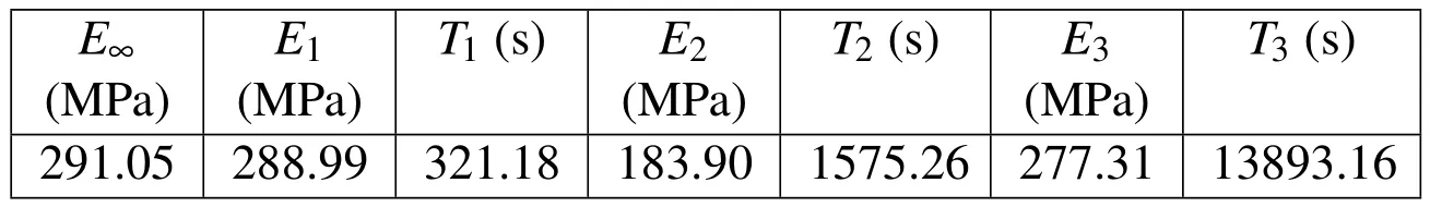
Table 3:Viscoelastic model parameters of the studied HDPE at room temperature.
Using Eq.7 allows us,to check the validity of Eq.17 in the calculations that follow.Figure 14 shows the results ofE(t)calculated by using ε33(t)obtained by theFEmethod(Figure 15)compared withE(t)calculated directly by Eq.17.We note that we have imposed an axial stress equal to 1MPaat the end of the rod,the same limit conditions was applied.Thus,Figure 14 shows an agreement ofE(t)calculated directly by Eq.17 withE(t)calculated by dividing axial strainFEoutput(Figure 15)by instantaneous applied stress.
So the simulation by finite element method is reliable and can be replaced by analytical equation.Based on these results,we propose to develop an analytical expression forJ,involvingE(t)given by Eq.17,and the shape function which is determined by Eq.4 above.Once the expressions ofF(Eq.4)and the expression ofE(t)expressed by Eq.17 are found,we formulate the expression of theJintegral using the expression ofSIF Kgiven by Eq.1.


Figure 14:Comparison between FE results and analytical viscoelastic model(E(t))calculated with Eq.17.

Figure 15:Finite element results strains vs.time.
Where,Jelis the elastic domain ofJ,therefore;viscoelastic expression ofJis obtained by substitutingEbyE(t)expressed in Eq.17,and using the expression ofFfor the deepest point of the crack(pointAin Figure 1)
ViscoelasticJintegral is written as

That gives the dependant-time analytical expression ofJ(t)as a function ofF,which depends on surface crack parameters,E(t)which is function of creep time,and of course,the remote axial stress as a constant throughout time and the crack depth

This work deals with the problem of viscoelastic fracture of a cylindrical rod.Thus,as shown in Figure 14,the viscoelastic model developed after calibration of a relaxation test on a specimen HDPE is highly reliable owing to accurately reproduces the response to loading of the rod for a given period.Nevertheless,and given the tremendous effort in time and resources,e.g.memory space allocated to the storage of meshes and output data for post-processing,it is convenient for an engineer to possess means simple calculations.Simply,the analytical method,that provides proven effectiveness.Of course,it should be accompanied by the finite element method which is the further widely used,especially for complicated problems.For the constant loading,the stress intensity factors for the crack in a linear viscoelastic material are invariable along with time and their values are the same as those for the corresponding elastic material[Duan(2012];Leiet al.(2012)].So the latter case can be referred to check the validity of the developed expression.Figure 16(a)to 16(d)summarize certain results of the J-integral calculated by the analytical relation proposed here.Comparisons between them and the results extracted from the numerical simulation byFEM,give satisfaction,however,it should be noted that deviations were observed for long load times,which can be explained by the accumulation of error with increasing iterations,taking into account the discrepancies of approximation.
Figure 17(a)and 17(b)illustrate this last observation for periods of loading up to 90,000 seconds,where the difference between the results is pronounced for periods exceeding 30 000 seconds in both cases,the results always converge to oneJvalue which remains constant whenE(t)reachesE∞.Both curves of Figs 17(a)and 17(b)converge to the same horizontal asymptote that takes the value ofJ∞,in finiteJis specific for each cracks con figuration,it depends of course on the value of the shape function.

Figure 16:Energy release rate(J-integral)of the HDPE rod subjected to tension at the deepest point A.(a).Comparison between analytical and FE results for crack size ratio 0.15and crack shape ratio 0.4.(b)crack size ratio 0.15 and crack shape ratio 0.9;(c)crack size ratio 0.2 and crack shape ratio 0.4 and(d)crack size ratio 0.2 and crack shape ratio 0.5

Figure 17:Long term energy release rate(J-integral)of HDPE rod subjected to tension for the deepest point A.(a)Comparison between analytical and FE results for crack size ratio 0.2 and crack shape ratio 0.1(b)crack size ratio 0.35 and crack shape ratio 0.9
For example,in the case wherea/D=0.35 anda/c=0.9(Fig.17(b)),Jconverges to 0.0660MPa.mmfor the finite element method and to 0.0636MPa.mmfor the analytical method.So if we consider the simulation results as a reference,we can estimate relative errors equal to 3.63 percent for the first case and 4.78 percent in the case ofa/D=0.2 anda/c=0.1(Figure 17(a)),Considered eligible in numerical approximations.
5 Conclusion
This work deals with the problem of viscoelastic fracture of a cylindrical rod.However,a normalizedSIFis determined for an arbitrary elastic material; it is applicable to HDPE of study.The results of this work show that
-The NormalizedSIFis independent of the material.Moreover,it depends on the parameters of the crack surface.
-Knowledge of the stress intensity repartition along the crack front,by using a simple analytical expression of the normalizedSIF,gives access toJas a rupture parameter that is widely used for its simplicity and its experimental determination established.
-Results of this work allowed developing a simple analytical expression giving the time-dependentJintegral involving the Young’s modulus which is itself a function of time and the shape function.
-The correspondence principle between elastic and viscoelastic problem has been used,the numerical simulations give similar results to those calculated by the expression developed in this work,consequently,theJintegral method,by its simplicity,can be exploited in the case of a viscoelastic medium such as HDPE.
-Because very small computational burden is needed,the current Method is very suitable for fracture analyse of 3D structures such as cylindrical rod with a semielliptical crack
-A more detailed study is in progress,where the use of the correspondence principle will be retained in the case of pressurized HDPE pipes containing cracks in different positions and a more rigorous shape function will be necessary
AbaqusVersion 6.9 Documentation.Dassault Systmes Simulia Corp.,Providence,R I,USA,2009.
Benhamena,A.;Aminallah,L.;Bouiadjra,B.B;Benguediab,M.;Amrouche,A.;Benseddiq,N.(2011):Jintegral solution for semi-elliptical surface crack in high density poly-ethylene pipe under bending.Mater Design.,vol.32,no.5,pp.2561-2659.
Bush,J.(1981):Stress intensity factors for single-edge-crack solid and hollow round bars loaded in tension.J.Test.Eval.,vol.9,no.4,pp.216-223.
Cai,C.Q.;Shin,C.S.(2005):A normalized area-compliance method for monitoring surface crack development in a cylindrical rod.Int.J.Fatigue.,vol.27,no.7,pp.801-809.
Carpinteri,A.(1992):Stress intensity factors for straight-fronted edge cracks in round bars.Eng.Frac.Mech.,vol.42,no.6,pp.1035-1040.
Creus,G.J.(1986):Viscoelasticity-basic theory and applications to concrete structure.Springer-Verlag.,pp.28-29
Danton,G..L.(2002):Initiation J-integral for linear viscoelastic solids with constant Poisson’s ratio.Int.J.Fract.,vol.113,no.1,pp.27-37.
Daoud,O.E.K.;Cartwright,D.J.(1985):Strain energy release rate for a circular-arc edge crack in a bar under tension or bending.J.Strain.Anal.Eng.Design.,vol.20,no.1,pp.53-58.
Daoud,O.E.K.;Cartwright,D.J.;Carney,M.(1978):Strain-energy release rate for a single edge-cracked circular bar in tension.J.Strain.Anal.Eng.Design.,vol.13,no.2,pp.83-89.
Dong,L.;Atluri,S.N.(2012):SGBEM(Using Non-hyper-singular Traction BIE),and super elements,for non-collinear fatigue-growth analyses of cracks in stiffened panels with composite-patch repairs.CMES:Computer Modeling in Engineering&Sciences,vol.89,no.5,pp.417-458.
Dong,L.;Atluri,S.N.(2012):SGBEM Voronoi Cells(SVCs),with embedded arbitrary shaped inclusions,voids,and/or cracks,for micromechanical modeling of heterogeneous materials.CMC:Computers,Materials&Continua,vol.33,no.2 pp.111-154.
Dong,L.;Atluri,S.N.(2013):Fracture&fatigue analyses:SGBEM-FEM or XFEM?Part 1:2D structures.CMES:Computer Modeling in Engineering&Sciences,vol.90,no.2,pp.91-146.
Dong,L.;Atluri,S.N.(2013):Fracture&fatigue analyses:SGBEM-FEM or XFEM?Part 2:3D solids.CMES:Computer Modeling in Engineering&Sciences,vol.90,no 5,pp.379-413.
Duan,J.;Lei,Y.;Li,D.(2012):Enriched finite element method for 2-D and 3-D blunt crack problems in a viscoelastic medium.J.Mechl.Scie.Tech.,vol.26,no.3,pp.869-882.
Dubois,F.;Chazal,C.;Petit,C.(2001):Viscoelastic crack growth process in wood timbers:an approach by the finite element method for mode I fracture.Inte.J.Fracture.,vol.113,no.4,pp.367-388.
Findley,K.O.;Koh,S.W.;Saxena,A.(2007):J-integral expressions for semielliptical cracks in round bars.Inte.J.Fatigue.,vol.29,no.5,pp.822-828.
Forman,R.G.;Shivakumar,V.(1986):Growth behavior of surface cracks in the circumferential plane of solid and hollow cylinders.Fracture Mechanics:Seventeenth Volume.J.H.Underwood,R.Chait,C.W.Smith,D.P.Wilhelm,W.A.Andrews and J.C.Newman(Eds.).ASTM STP 905,Philadelphia:pp.59-74.
Hernández,A.J.;Hernández,S.J.;Macias-García,A.;Sánchez-González,J.(2001):Relaxation modulus in PMMA and PTFE fitting by fractional Maxwell model,Polym.Test.,vol.21,no.3,pp.325-331.
Ismail,A.E.;Arif fin,A.K.;Abdullah,S.;Ghazali,M.J.(2012):Stress intensity factors for surface cracks in round bar under single and combined loadings.Meccanica.,vol.47,no.5,1141-1156.
Knauss,W.G.(1973):The mechanic of polymer fracture Applied.Mechanics Reviews.,vol.26,pp.1-17.
Lei,Y.J.;Duan,J.B.;Li,D.K.;Li,X.F.(2012):Crack problems in viscoelastic medium using enriched finite element method.Int.J.Mech.Sci.,vol.58,pp.34-46.
Mackay,T.L.;Alperin,B.J.(1985):Stress intensity factors for fatigue cracking in high-strength bolts.Eng.Frac.Mec.,vol.1,no.21,pp.91-97.
Marc,D.;Hung,N.(2004):Fatigue crack growth analysis by an enriched meshless method.J.Comp.Appl.Math.,vol.168,no.1-2,pp.155-64.
Marc,D;Hung,N.(2004)Fatigue crack growth analysis by an enriched meshless method.J.Comput.Appl.Math.,vol.168,pp.155-164.
Marques,S.P.C;Creus,G.J.(2012):Solutions with Abaqus in Computational Viscoelasticity.Springer Briefs in Computational Mechanics.,pp.103-111.
Masuero,J.R.;Creus,G.J.(1993):Finite elements analysis of viscoelastic fracture.Inte.J.Fracture.,vol.60,pp.267-282.
Nguyena,V.P.;Rabczuk,T.;Bordas,S.(2008):Meshless methods:a review and computer implementation aspects.Math.Comp.Simulation.,vol.79,no.3,pp.763-813.
Park,S.W.;Schapery,R.A.(1999):Methods of inter-conversion between linear viscoelastic material functions.Part I:a numerical method based on Prony series.Inte.J.Solid.Stru.,vol.36,pp.1653-1675.
Raju,I.S.;Newman,J.C.(1986):Stress-intensity Factors for circumferential surface cracks in pipes and rods under tension and bending loads.ASTM special technical publication,vol.905,pp.789-805.
Riadh,E.;Wafa,T.(2006):Viscoelastic Behavior of HDPE Polymerusing Tensile and Compressive Loading.J.Mater.Eng.Perform.,vol.15,no.1,pp.111-116.
Rice,J.R.(1968):A path independent integral and the approximate analysis of strain concentration by notches and cracks.J Appl Mech.,vol.35,pp.379-386.
Schapery,R.A.(1984):Correspondence principles and a generalized J integral for large deformation and fracture analysis of viscoelastic media.Inte.J.Fracture.,vol.25,no.3,pp.195-223.
Schapery,R.A.(1990):On some path independent integrals and their use in fracture of nonlinear viscoelastic media.Inte.J.Fracture.,vol.42,no.2,pp.189-207.
Shin,C.S.;Cai,C.Q.(2004):Experimental and finite element analyses on stress intensity factors of an elliptical surface crack in a circular shaft under tension and bending.Inte.J.Fracture.,vol.129,pp.239-264.
Stavros,S.;Jiangwei,W.(2008):Evaluation of polymer fracture parameters by the boundary element method.Eng Frac Mech.,vol.75,no.5,pp.1251-1265.
Tian,L.;Dong,L.;Bhavanam,S.;Phan,N.,Satya,N.A.(2014):Mixed-mode fracture&non-planar fatigue analyses of cracked I-beams,using a 3D SGBEMFEM Alternating Method.Theoretical and Applied Fracture Mechanics,vol 74,pp.188-199.
Tomita,Y.;Uchida,M.(2005):Computational Characterization and Evaluation of Deformation Behavior of Spherulite of High Density Polyethylene in Mesoscale Domain.CMES:Computer Modeling in Engineering&Sciences.,vol.10,no.3,pp.239-248.
Warby,M.K.;Walton,J.R.;Whiteman,J.R.(1992):A finite-element model of crack-growth in a finite body in the context of mode-I linear viscoelastic fracture.Comput.Meth.Appl.Mech.Eng.,vol.97,no.3,pp.375-397.
Wilhem,D.;Fitz Gerald,J.;Carte,J.;Dittmer,D.(1982):An empirical approach to determining K for surface cracks.Proceedings of the 5th international Conference on Fracture Research,pp.11-21.
Williams,J.G.(1984):Fracture Mechanics of Polymers.Ellis Horwood Limited,New York.
1University of Mustapha Stambouli,B.P 305,Mascara,Algeria.
2University Lille 1,Bd P.59655 Villeneuve d’Ascq,France.
3University of Djilali Liabès,Sidi Bel Abèss,Algeria.
杂志排行

Computers Materials&Continua的其它文章
- Flexoelectricity in Solid Dielectrics:From Theory to Applications
- Analytical Solution of Thermo-elastic Stresses and Deformation of Functionally Graded Rotating Hollow Discs with Radially Varying Thermo-mechanical Properties under Internal Pressure
- The Influence of Gravitational Field on Generalized Thermoelasticity with Two-Temperature under Three-Phase-Lag Model