SiO2/炭泡沫和SiC/炭泡沫复合材料的制备及表征
2015-12-05吴晓栋邵高峰沈晓冬南京工业大学材料科学与工程学院材料化学国家重点实验室南京0009宿迁市南京工业大学新材料研究院宿迁800中航复合材料有限公司先进复合材料国防科技重点实验室北京000
吴晓栋 邵高峰 崔 升 王 岭 沈晓冬*,(南京工业大学材料科学与工程学院材料化学国家重点实验室,南京 0009) (宿迁市南京工业大学新材料研究院,宿迁 800) (中航复合材料有限公司,先进复合材料国防科技重点实验室,北京 000)
SiO2/炭泡沫和SiC/炭泡沫复合材料的制备及表征
吴晓栋1,2邵高峰1,2崔升1,2王岭3沈晓冬*,1,2
(1南京工业大学材料科学与工程学院材料化学国家重点实验室,南京210009) (2宿迁市南京工业大学新材料研究院,宿迁223800) (3中航复合材料有限公司,先进复合材料国防科技重点实验室,北京101300)
对炭泡沫为支撑骨架的氧化硅气凝胶(SiO2/炭泡沫)和碳化硅(SiC/炭泡沫)复合材料分别采用XRD、SEM、激光导热仪、万能力学试验机进行物相、微观结构、热学及力学性能方面的表征。结果表明:所制备的SiO2/炭泡沫与原炭泡沫相比,具备更高的抗压强度(14.95 MPa)和更低的室温热导率(0.44 W·m-1·K-1)。SiC/炭泡沫材料则保持了较高的抗压强度值(14.66 MPa),其在1 200℃下具备极低的高温热导率(2.18W·m-1·K-1)。热重分析表明,SiC/炭泡沫在氧化氛围中到610℃才发生质量的损失,而内部炭发生完全烧蚀的温度高达844℃,这表明该材料的抗氧化性能远好于纯的炭泡沫材料。
炭泡沫;二氧化硅;碳化硅;热稳定性;热导率;抗压强度
0 Introduction
Glassy carbon foams are porous carbon materials with many advantages such as low density,high specificmodulusandstrength,highapplicable temperature,large surface area,coupled with either controllable electrical conductivity or low thermal conductivity[1-3].The performances of the carbon foams such as low density and excellent insulation make them attractive candidates for application in advanced aircraft,spacecraft and related industries[4-6].Unfortunately,carbon foam has some key drawbacks that limit its performance in certain cases.Firstly,carbon foam has a fairly low thermal stability in oxidizing atmosphere at elevated temperatures,thus limiting the operatingtemperatureofcarbonfoam-supported materials in an oxidative environment.Secondly,the pristine carbon foam has a relatively higher thermal conductivity,compared with aerogel composite and fiber mat[7-12],which is not favorable to thermal insulations and other applications.Luo et al.[2]proposed a resin-derived carbon foam reinforced by K2Ti6O13whiskers,and showed that the addition of K2Ti6O13whiskerswithcontentof2wt% ~4wt%enhanced thermal insulating properties of the neat carbon foams, whereas the compressive strength was below 8 MPa. Furthermore,the compressive strength of most pristine carbon foam is unsatisfying,which has sometime limited its applications in aviation and aerospace fields.Zhang et al.[6]employed arylacetylene as the precursor to produce carbon foam with a compressive strength of 25.8 MPa and low bulk density of 0.6 g· cm-3,however,thethermalpropertieswerenot evaluated in the article.
Covering the inner surface of carbon foam with a more thermally stable material to serve as a barrier to oxygen diffusion is a common way to improve the thermalstability.However,thermalstabilityis typically improved but the porous carbons are blocked by the depositing species,thus increasing the thermal conductivity of neat carbon foam.SiO2aerogels are unique porous materials with distinctive properties, such as large specific surface area,low thermal conductivity[7-8,13-14].It has been demonstrated that both SiO2and SiC are well known for their good thermal stability at high temperatures[15-18].Therefore,incorporating SiO2aerogel into carbon foam can not only improve its resistance to oxidation at elevated temperatures, but also decrease its thermal conductivity at room temperature.In the past few years,much attention has been paid to the study of aerogel/carbon foam composites to further decrease the thermal conductivity and increase the compressive strength of carbon foam[19-21]. The SiC derived from the reaction of carbon foam and SiO2aerogel at high temperatures can further improve its thermal stability and decrease high temperature thermal conductivity due to the enhanced radiation extinction of SiC particles.On the other hand,the drawback of low compressive strength can be solved by properly increasing the density of carbon foam sincethecompressivestrengthandthermal conductivity are positively correlated with carbon foam density[2].Thus,the preparation and characterization of resulting carbon foam supported SiO2/Carbon foam and SiC/Carbon foam compositeare worthwhile.
In this study,we use carbon foam as scaffolds for the synthesis of high strength SiO2/Carbon foam and SiC/Carbon foam composites with enhanced thermal stability and low thermal conductivity.A new method of producing SiC particles using carbon foam as carbon source and silica aerogel as silicon source is developedinthisarticle.Theinfluenceof incorporating SiO2aerogel and produced SiC particles onthemicrostructure,thermalandmechanical properties of the pristine carbon foam are investigated via scanning electron microscopy(SEM),the laser flash technique,and mechanical testing.
1 Experimental
1.1Sample preparation
Tetraethyl orthosilicate(TEOS,A.R.,Sinopharm Chemical Reagent Co.,Ltd.)was used as silicon source.Hydrochloric acid(HCl,1 mol·L-1,Shanghai Zhongshi Chemical Co.,Ltd.)and ammonia solution (NH3·H2O,1 mol·L-1,Wuxi City Yasheng Chemical Co.,Ltd.)were used as catalysts.Deionized water(homemade)was used as hydrolysis agent and absolute ethylalcohol(EtOH,AR,WuxiCityYasheng Chemical Co.,Ltd.)as solvent.All of the reactants and solvents were used as received without further purification.Carbonfoamwasobtainedfrom bituminous coal by a two-stage procedure according to reference[22].The precursor was first loaded in the reactor and was pressurized with argon until the initial pressureof approximately 3~4 MPa,and then it was heated to temperature of 450~600℃ with a heating rate of 2~4℃·min-1and kept at that temperature for 2 h.In a second stage,the precursor was carbonized underflowingargonatmosphereattemperature between 850~1 200℃ and maintained at that level for 2 h to produce the final carbon foam.In a typical synthesis,TEOS(22.4 mL,0.1 mol)was firstly dissolved in a mixture of water(7.2 mL,0.4 mol)and ethanol(93 mL,1.6 mol).Secondly,appropriate amount of HCl(0.3 mL,0.3 mmol)was added to the mixture with pH value of 2~3 after stirring for about 90 min at 50℃.Thirdly,desired amount of NH3·H2O (0.5 mL,0.5 mmol)was added to the solution to accelerate the poly-condensation rate.At last,the reaction mixture was further stirred for 10 min, transferred to a container with carbon foam(35 mm× 35 mm×20 mm)under vacuum for full infiltration. After gelation within 3 h under room temperature,the wet gel composite was aged at room temperature for 1 d and was subsequently soaked in a bath of absolute ethanol in an oven of 50℃for 3 d to exchange the water and reaction byproducts from the pores of the materials.After aging and solvent exchange,the wet gels composites were put in the critical point extractor fordrying,usingCO2supercriticalfluiddrying technique,thusformingtheSiO2/Carbonfoam composite.Afterdrying,theSiO2/Carbonfoam composite was heated at 1500℃and was maintained at that level for 5 h in a tube furnace under flowing argon(100 mL·min-1)to produce the SiC/Carbon foam composite.
1.2Sample characterization
X-ray diffraction(XRD)patterns were recorded using a Rigaku Smart Lab 3000 diffractometer with Cu Kα radiation(λ=0.154 18 nm).The X-ray tube was operated at 35 kV and 30 mA.The optics configuration includes a fixed divergence slit(0.5°) and a D/teX Ultra detector.The measurements were collected over a 2θ range of 10°~80°,at a rate of 10℃·min-1.Scanning electron microscopy(SEM)images were obtained with a JSM-6510 scanning electron microscope.The accelerating voltage was between 3.0~5.0 kV,and the samples were coated with platinuminvacuum.Thermalgravimetricanalysis (TGA)and differential scanning calorimetry analysis (DSC)wereperformedbyNETZSCHSTA449C Thermogravimetricanalyzer under a constant air flow of 30 mL·min-1at a heating rate of 10℃·min-1to 1 000℃.The compressive strengths of the samples weremeasuredbyanINSTRON3382testing machine.The test temperature was 25℃ and the cross-head speed applied was 1.0 mm·min-1.The thermal conductivities of samples(10 mm×10 mm×3.4 mm)were measured using Netzsch LFA427 laser-flash method under a dynamic argon atmosphere(80 mL· min-1,0.1 MPa).InSb was used as an infrared detector.The sample was coated with graphite to increase the pulse energy absorption and infrared emittance,and the pulse width was fixed at 0.5 ms and laser voltage of 450 V.
2 Results and discussion
Fig.1 shows the photographs and SEM images of pristine carbon foam.The bulk density and porosity of the pristine carbon foam are 0.50 g·cm-3and 76%, respectively,usingthetraditionalArchimedes method[4].The density is much larger than other carbonfoams[23],whichisfavorabletohigh compressive strength.As can be seen from Fig.1(b), there are opening pores as well as obturator pores in the cell walls of carbon foam.The presence of obturator pores origins from the fast growing viscosity which inhibits the growth of pores inside during the process of heating mesophase pitch.Fig.1(c)shows that some small cracks appear in the cell walls,and they are caused by two reasons.The first one is attributed to the diffusivity of light gas stemming fromnonecarbon-basedelementintheprocessof carbonization.The other one can be explained by the large stress due to the shrinkage of carbon foam skeleton when it is heated at elevated temperatures[3]. It can be observed in Fig.1(d)that carbon foams have an open-cell and spherical-shape porous structure as well as dense structures,and most pores within carbon foam distribute in the range of 400~700 μm.There are also some small windows with diameters of 100~300 μm in the cell walls,owing to the incomplete growing of carbon particles[4]combined with voids formed in thermal decomposition[24].

Fig.1 Photographs(a)and SEM images(b,c and d)of the pristine carbon foam

Fig.2 Photographs(a,b)and SEM images(c,d)of SiO2/Carbon foam and SiC/Carbon foam composite
Fig.2 shows the photographsand SEM images of SiO2/Carbon foam and SiC/Carbon foam composite.SiO2aerogel is sufficiently infiltrated in the pores of carbon foam skeleton,combining well with the cell wall as can be seen from Fig.2(c)and further amplificationin inset of Fig.2(c).The size of SiO2nano particles is ca. 40 nm,and they are cellular solids similar to a pearl necklace,of which the structure is beneficial to lower thermal conductivity.SiC particles(arrow directed ones)appear as disordered arrangements with grain size of approximately 5 μm and are produced mainly in the surface of the carbon foam,as indicated in Fig. 2(d)and amplification inset.In addition,the cell walls become coarser and thinner after thermal treatment at 1 500℃,in comparison with the pristine carbon foam.The total process of the reduction of SiO2to SiC may occur according to the following equation[25-29]:

Fig.3 shows the XRD patterns for the pristine carbon foam,SiO2/Carbon foam and SiC/Carbon foam composite.As can be seen,the XRD pattern for the pristine carbon foam is similar with the SiO2/Carbon foam composite.Two wide and weak peaks around 25° and 43°are detected and they are diffractions from typical crystal faces of(002)and(100)with graphite characteristics[30].However,it is not as narrow and intense as reference[31]since the carbonization temperature is not high enough to form the total graphitephase.The intense peaks in the XRD pattern for the SiC/Carbon foam composite can be indexed to SiC (PDF No.49-1623),and no other peaks are observed. However,the synthesized SiC particles is dramatically different from references[32-34].Therefore,based on XRD data,a 5 h treatment at 1 500℃is sufficient to convert the SiO2layer in SiO2/Carbon foam to SiC particles.According to reference[9],SiC particles are derived from multi-step reactions,and the initial process should follow Eq.2 to form SiO gas:

Then,SiC can be produced by two different ways according to Eq.3 and Eq.4 as follows:
CO(g)from Eq.2 and Eq.3 can react with SiO2(s) to produce more SiO(g)via Eq.5 to keep the reaction running,and the CO2from Eq.4 and Eq.5 will be consumed by the surrounding carbon foam to form CO (g)as Eq.6:

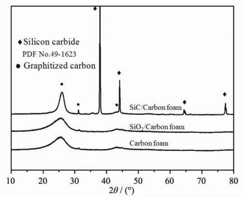
Fig.3 Powder XRD patterns for carbon foam,SiO2/Carbon foam and SiC/Carbon foam composite

The morphology of SiC is closely related to its reaction pathway.In general,the products of Eq.4 are SiC whiskers whereas Eq.3 produces SiC particles.In this work,the produced SiC exists as particleswith grain size of ca.5 μm as indicated by Fig.2(d).This phenomenon can be caused by two reasons.On one hand,the porosity of carbon foam is very high,which results in the low partial pressure of SiO(g)and CO(g) and inhibits the proceeding of Eq.4.On the other hand,carbon foam possesses large interconnecting pores,favoring the diffusion of SiO(g),thus accelerating the formation of SiC particles as Eq.3.
Fig.4 shows the TGA,DSC and DTG curves of carbon foam,SiO2/Carbon foam and SiC/Carbon foam composite.As expected,combustion of the pristine carbon foam begins at 572℃ and the material is completely consumed at 766℃.The remaining mass is 12%of the original material,which indicates that the mass fraction of carbon in the foam is 88%.The mass loss at around 220℃ of SiO2/Carbon foam composite is attributed to further condensation of Si-OH as well as the removal of surface water absorbed in the pores of SiO2aerogel,thus two exothermic peak at 244℃and 654℃are observed on the corresponding DSC thermogram.The onset temperature of carboncombustionfortheSiO2/carbonfoamcompositeis almost the same as that for the pristine carbon foam, suggesting that SiO2aerogel is not an effective barrier to oxygen diffusion.This material retains ca.22%of its original mass due to the presence of the SiO2overcoat.Improvement of thermal stability is observed in the SiC/Carbon foam composite.Mass loss does not begin until about 610℃,and complete oxidation of the carbon foam does not occur until 844℃ . According to the Fig.4(c),there is little weight gain at elevated temperatures in air atmosphere caused by oxidation of SiC particles,which is consistent with reference[16].The improved thermal stability suggests that SiC covers most of the carbon foam surface, providing an effective barrier to oxygen diffusion.The remaining mass is 19%,lower than mass loss of SiO2/ Carbon foam composite.It can be inferred that the SiO2content in SiO2/Carbon foam composite is 10%, and the SiC content in SiC/Carbon foam composite is 7%,thus the mass ratio of SiC to SiO2is 70%.It is consistent with Eq.1 which shows a theoretical ratio of 67%,indicating that SiO2layer in SiO2/Carbon foam compositeis totally converted to SiC particles.

Fig.4 TGA(a),DSC(b)and DTG(c)plots of carbon foam,SiO2/Carbon foam and SiC/Carbon foam composite
Fig.5 shows the thermal conductivities(λ)of carbon foam,SiO2/Carbon foam and SiC/Carbon foam composite as a function of testing temperature.The results are calculated by Eq.7 as follows:


Fig.5 Thermal conductivity of carbon foam,SiO2/Carbon foam and SiC/Carbon foam composite as a function of testing temperature
where ρ is the bulk density of the sample,C is the specific heat capacity and α is the thermal diffusivity.As can be seen from Fig.5,the thermal conductivities at room temperature for carbon foam, SiO2/Carbon foam and SiC/Carbon foam compositeare 0.67,0.44 and 0.52 W·m-1·K-1,respectively.It can be inferred that the incorporation of SiO2aerogel can decrease its thermal conductivity at room temperatureby 31%of the original value of carbon foam.When the temperature is less than 900℃,the thermal conductivity of carbon foam and SiO2/carbon foam composite both increases slowly with the increase of temperature,whereas sharply increases after 900℃. SiC/Carbon foam composite shows a much lower increase inthermal conductivity at temperature over 900℃,in comparison with carbon foam and SiO2/ Carbon foam.It can be explained by the theory of thermalphysicsdescribingthetotalthermal conductivity in carbon foam composites as follows:

where λsis the conduction through solids,λgis the conduction through gas,λcis the convection within the cells,and λris the radiation through the cell walls and the voids.
In the pristine carbon foam,the volume fraction of solid phase is as low as 24%,therefore the solid conductivityviaphonontransportislowatroom temperature.The average pore size(400~700 μm) within carbon foam would suppress the convective heattransferandradiationisalsoreducedby adsorption and the repeated reflection from the cell walls.Thus,carbon foam possesses a relatively low thermal conductivity of 0.67 W·m-1·K-1,which is lower than literature reports[35-36].When SiO2aerogel is incorporated in carbon foam,phonon transport through the amorphous carbon and cell walls partly transfers to aerogel part,which needs a much larger heat transfer path than before,thus the solid conduction is inhibitedtoalargeextent,andthethermal conductivity is reduced to 0.44 W·m-1·K-1[37].When the temperature is below 900°C,the increased thermal conductivity of the three samples is caused by the increasedsolidconductivity,whilethesharply increasedthermalconductivityiscausedbythe increase of thermal radiation,because the thermal radiation plays the greatest role for the thermal conductivity of carbon foam and SiO2/Carbon foam composite.However,fortheSiC/Carbonfoam composite,thermal conductivity increases slowly at temperatures over 900℃,in comparison with the other two materials.This can be explained by the produced SiC particles,playing a part as an opacifier at elevated temperatures.The formation of SiC can increase the specific extinction of the composite, which would decrease the thermal radiation,thus the SiC/carbonfoamcompositepossessesthelowest thermal conductivity at high temperatures[38-39].
Fig.6 shows the compressive load-strain curves of carbon foam,SiO2/Carbon foam and SiC/Carbon foam composite.The curves indicate that the samples are typical brittle materials with no plateau stresses, which is different from reference[40].The compressive strength of the three samples is 13.76,14.95 and 14.66 MPa,respectively.The incorporation of SiO2in theporesofcarbonfoamslightlyimprovesits compressive strength due to the strengthen effect of cell wall and junctions of carbon foam.In addition, the SiC/Carbon foam composite possesses a slightly lower compressive strength than SiO2/Carbon foam.It is attributed to the decreased thickness of cell walls, damagedligamentsandjunctionsafterthermal treatment at 1 500℃ since tough framework of the carbonfoamsisunfavorabletohighmechanical properties,as indicated by SEM images in Fig.2(d). However,the compressive strength of SiC/Carbon foam composite is much larger than other carbon foams with similar density[41-42].

Fig.6 Compressive load-strain curves of carbon foam, SiO2/Carbon foam and SiC/Carbon foam composite
3 Conclusions
We have demonstrated a method for the synthesis of SiO2/Carbon foam and SiC/Carbon foam composite with sol-gel method,followed by thermal treatment under flowing argon.In comparison with the pristinecarbonfoam,theresultingSiO2/Carbonfoam composite has a slightly higher compressive strength (14.95 MPa)and a much smaller thermal conductivity (0.44 W·m-1·K-1).The SiC/Carbon foam composite maintains a high compressive strength of 14.66 MPa and possesses a rather low thermal conductivity(2.18 W·m-1·K-1)at temperature as high as 1 200℃.In addition,theSiC/Carbonfoamcompositegains improved oxidative thermal resistance than pristine carbon foam.This new class of high compressive strength materials with improved thermal stability in oxidizingatmosphereshouldbeespecially advantageous in potential applications where high compressive strength,low thermal conductivity,and operation at elevated temperatures are desired.
[1]Wu X W,Fang M H,Mei L F,et al.Mater.Sci.Eng.A,2012, 558:446-450
[2]Luo R Y,Ni Y F,Li J S,et al.Mater.Sci.Eng.A,2011,528 (4/5):2023-2027
[3]XIAO Feng(肖锋),ZHANG Hong-Bo(张红波),Xiong Xiang(熊翔),et al.Chinese J.Nonferrous Met.(中国有色金属学报),2010,20(7):1346-1352
[4]HeX,TangZH,ZhuYF,etal.Mater.Lett.,2013,94:55-57
[5]Sihn S,Roy A K.J.Mech.Phys.Solids,2004,52(1):167-191
[6]LI Kai(李凯),LUAN Zhi-Qiang(栾志强).New Carbon Mater.(新型炭材料),2004,19(1):77-78
[7]Neugebauer A,Chen K,Tang A,et al.Energy Build.,2014, 79:47-57
[8]Wei G S,Liu Y S,Zhang X X,et al.J Non-Cryst.Solids, 2013,362:231-236
[9]Sun H R,Zhang S C,Deng Z W,et al.Key Eng.Mater., 2014,602:126-129
[10]Xie T,He Y L,Hu Z J.Int.J.Heat Mass Transfer,2013,58 (1/2):540-552
[11]Liao Y D,Wu H J,Ding Y F,et al.J.Sol-Gel Sci.Technol., 2012,63(3):445-456
[12]Jung I K,Gurav J L,Ha T J,et al.Ceram.Int.,2012,38(1): 105-108
[13]Wei G S,Liu Y S,Zhang X X,et al.Int.J.Heat Mass Transfer,2011,54(11):2355-2366
[14]ZHANG Jun-Jun(张君君),ZHONG Ya(仲亚),SHEN Xiao-Dong(沈晓冬),et al.Chinese J.Inorg.Chem.(无机化学学报),2014,30(4):793-799
[15]LIN Jian-Xin(林建新),ZHENG Yong(郑勇),ZHENG Ying (郑瑛),et al.Chinese J.Inorg.Chem.(无机化学学报), 2006,22(10):1778-1782
[16]Worsley M A,Kuntz J D,Satcher J J,et al.J Mater.Chem., 2010,20(23):4840-4844
[17]Labat G A,Zollfrank C,Ortona A,et al.Ceram.Int., 2013,39(2):1841-1851
[18]KONG Yong(孔勇),SHEN Xiao-Dong(沈晓冬),CUI Sheng (崔升),et al.Chinese J.Inorg.Chem.(无机化学学报), 2014,30(12):2825-2831
[19]SHI Ya-Chun(史亚春),LI Tie-Hu(李铁虎),WANG Xi-Lin (王习林),et al.Funct.Mater.(功能材料),2013,44(20):3049 -3052
[20]DU Shan(杜姗).Thesis for the Master′s Degree of Harbin Institute of Technology(哈尔滨工业大学硕士学位论文), 2013.
[21]HUANG Peng(黄鹏).Thesis for the Master′s Degree of Harbin Institute of Technology(哈尔滨工业大学硕士学位论文),2013.
[22]Calvo M,Garcia R,Arenillas A,et al.Fuel,2005,84(17): 2184-2189
[23]Feng J Z,Feng J,Jiang Y G,et al.Mater.Lett.,2011,65 (23/24):3454-3456
[24]Lin Q L,Luo B,Qu L J,et al.J.Anal.Appl.Pyrolysis, 2013,104:714-717
[25]Leventis N,Sadekar A,Chandrasekaran N,et al.Chem. Mater.,2010,22(9):2790-2803
[26]Li X T,Chen X H,Song H H.Mater.Sci.Eng.B,2011,176 (1):87-91
[27]Mishra S B,Mishra A K,Mamba B B,et al.Mater.Lett., 2011,65(14):2245-2247
[28]Li X T,Chen X H,Song H H.J.Mater.Sci.,2009,44(17): 4661-4667
[29]XU Wu-Jun(徐武军),XU Yao(徐耀),SUN Xian-Yong (孙先勇),et al.New Carbon Mater.(新型炭材料),2006,21 (2):167-170
[30]Xu S J,Qiao G J,Wang H J,et al.Mater.Lett.,2008,62 (30):4549-4551
[31]Li S Z,Song Y Z,Song Y,et al.Carbon,2007,45(10):2092 -2097
[32]Kong Y,Zhong Y,Shen X D,et al.Mater.Lett.,2013,99: 108-110
[33]Saeedifar Z,Nourbakhsh A A,Kalbasi R J,et al.J.Mater. Sci.Technol.,2013,29(3):255-260
[34]Zhang N C,Yu A X,Liang A H,et al.J.Appl.Polym.Sci., 2013,130(1):579-586
[35]Wang X Y,Zhong J M,Wang Y M,et al.Carbon,2006,44 (8):1560-1564
[36]Mesalhy O,Lafdi K,Elgafy A.Carbon,2006,44(10):2080-2088
[37]Sihn S,Ganguli S,Anderson D P,et al.Compos.Sci.Technol., 2012,72(7):767-773
[38]Wang X D,Sun D,Duan Y Y,et al.J.Non-Cryst.Solids, 2013,375:31-39
[39]Xu L,Jiang Y G,Feng J Z,et al.Ceram.Int.,2015,41(1): 437-442
[40]Li X,Basso M C,Braghiroli F L,et al.Carbon,2012,50(5): 2026-2036
[41]Gallego N C,Klett J W.Carbon,2003,41(7):1461-1466
[42]SHEN Zeng-Min(沈曾民),GE Min(戈敏),CHI Wei-Dong (迟伟东),et al.New Carbon Mater.(新型炭材料),2006,21 (3):193-201
Preparation and Characterization of SiO2/Carbon Foam and SiC/Carbon Foam Composites
WU Xiao-Dong1,2SHAO Gao-Feng1,2CUI Sheng1,2WANG Ling3SHEN Xiao-Dong*,1,2
(1State Key Laboratory of Materials-Oriented Chemical Engineering,College of Materials Science and Engineering,Nanjing Tech University,Nanjing,210009,China) (2Advanced Materials Institute of Nanjing Tech University in Suqian,Jiangsu 223800,China) (3AVIC Composite Corporation Ltd.,National Key Laboratory of Advanced Composite,Beijing,101300,China)
The synthesis and characterization of carbon foam supported silica aerogel(SiO2/Carbon foam)and silicon carbide composite(SiC/Carbon foam)are presented in this study.The phase composition,microstructure, thermal and mechanical properties are investigated by XRD,SEM,LFA Laser Flashmeasurements,and Universal Material Testing.The resulting SiO2/Carbon foam composite shows a higher compressive strength(14.95 MPa)and a smaller thermal conductivity(0.44 W·m-1·K-1)at room temperature,in comparison with the pristine carbon foam.The SiC/Carbon foam composite maintains a compressive strength of 14.66 MPa,and possesses a low hightemperature thermal conductivity(2.18 W·m-1·K-1at 1 200℃).Mass loss does not begin until 610℃for the SiC/Carbon foam composite,and complete carbon combustion does not occur until 844℃,indicating a much better thermal stability than the pristine carbon foam in oxidizing atmosphere.
carbon foam;SiO2;silicon carbide;thermal stability;thermal conductivity;compressive strength
O613.7
A
1001-4861(2015)06-1252-09
10.11862/CJIC.2015.161
2015-03-08。收修改稿日期:2015-04-21。
江苏省高校优势学科建设工程项目(PAPD);长江学者和创新团队发展计划(No.IRT1146);江苏博士后研究基金计划项目(1402016A)资助。
*通讯联系人。E-mail:xdshen@njtech.edu.cn;Tel:025-83587234;会员登记号:E413200441M。