A Hydrodynamic Model for Dimpled Mechanical Gas Seal Considering Interaction Effect
2015-11-24ShiLiping时礼平HuangWei黄巍WangXiaolei王晓雷
Shi Liping(时礼平),Huang Wei(黄巍),Wang Xiaolei(王晓雷)*
A Hydrodynamic Model for Dimpled Mechanical Gas Seal Considering Interaction Effect
Shi Liping(时礼平)1,2,Huang Wei(黄巍)1,Wang Xiaolei(王晓雷)1*
1.College of Mechanical and Electrical Engineering,Nanjing University of Aeronautics and Astronautics,Nanjing 210016,P.R.China;
2.College of Mechanical Engineering,Anhui University of Technology,Ma’anshan 243002,P.R.China
The mechanical gas seal of aero engine has to face the problems of high wear rate and short lifetime.Surface texture has shown beneficial effects over the tribological characteristics.Here,a hydrodynamic model for dimpled annular area of mechanical gas seal considering the"interaction effect"between adjacent dimples is developed based on the Reynolds equation.Different multi-row columns are chosen and the dimensionless pressure in radial and circumferential directions is calculated.The results indicate that the"interaction effect"is more obvious in the circumferential direction than in the radial direction,even when the area and depth of the dimples are same.Moreover,for the 5×5 column,the dimensionless average pressure considering the"interaction effect"increases by 45.41%compared with the 1×5 column.Further analysis demonstrates that the model with the 5×5 column can be more reasonable with the consideration of reducing the calculation error caused by boundary conditions to investigate the hydrodynamic effect for dimpled mechanical gas seal.
surface texture;mechanical gas seal;hydrodynamic effect;interaction effect;aero engine
0 Introduction
The mechanical gas seal used for aero engine would be damaged easily because of high rotation speed,high temperature,great centrifugal forces and vibrations.Surface texturing has received a great deal of attention as a viable means to promote hydrodynamic effect,load carrying capacity and friction reduction[1-5].It has been used in mechanical seals[6-7],piston rings[8],sliding bearings[9-10],to name but a few.This improvement could be attributed mainly to the fact that the dimple serves as a micro-hydrodynamic bearing to generate additional hydrodynamic pressure to separate the mating surfaces and achieve non-contacting seal.In addition,every dimple also provides a pocket for wear particle embedment to prevent severe wear on the surfaces.
Over the past decades,a large number of theoretical and experimental works have been published on various aspects of liquid and gas seals.Etsion et al.[5]developed an analytical model to predict the relationship between the opening force and operating conditions of sealed rings.Experimental investigations were compared with the theoretical results.Etsion and Halperin[11]employed partial laser surface texture(LST)to enhance hydrostatic effects in high pressure seals.Mc Nikel and Etsion[12-14]developed a theoretical model to study the effect of partial LST on a hydrostatic gas seal,and optimized the LST gas seal performance in terms of the maximum film stiffness and the minimum gas leakage.In recent years,several theoretical models for mechanical seals based on solving the Reynolds equation,e.g,Ref.[15-17],and threetypes of numerical methods have been employed:finite element(FE),finite volume(FV)and finite difference(FD)[18-22].The FE and FV methods had disadvantages in the code development. FD method could develop computer code easily and both the convergence speed and stability of the FD solver could be enhanced by the aid of the successive-over-relaxation(SOR)iteration method.
From these studies above,one can conclude that they investigated single dimple locating within an imaginary rectangular cell of sides 2ri×2ri(riis the imaginary rectangular cell dimension)instead of annular area.Also they developed the model for calculations based on this unit neglecting the"interaction effect"between two neighboring dimples.However,as mentioned in Ref.[23],if the area ratio of dimples is more than 20%,the"interaction effect"of adjacent dimples should not be neglect.
The main goal of the analysis in the present work is to develop a hydrodynamic model located within annular area considering the"interaction effect"between two neighboring dimples for mechanical gas seal.Different multi-row columns containing circle shape structure dimples are chosen for evaluating the hydrodynamic pressure in radial and circumferential directions by numerical calculation.At the same time,the average dimensionless pressure of the whole seal surface is taken into account.The developed model is more accurate to study the hydrodynamic effect for dimpled mechanical gas seal.
1 Analytical Model
The mechanical gas seal model considered in this paper is represented by two non-contacting rings rotating relatively to each other(Fig.1). The regular network of dimples is distributed on the rotor surface(Fig.2).The gas fills in the dimples at a depth of hpand the gap between the rotor face and the stator surface with a depth of h0.The radius of the dimple is rpand the angle velocity of rotor ring isω.

Fig.1 Schematic diagram of partial mechanical gas seal

Fig.2 Geometrical model
The geometrical model is displayed in Fig.2. The method neglects curvature effect and consequently,a circular sector containing single-row column in the radial direction is assumed to be rectangular[6].Each dimple was located within an imaginary rectangular cell.What is more,the"individual effect"is considered only during the analysis of pressure distribution.Here,a developed model containing more accurate region is considered and different multi-row columns(3×5 column and 5×5 column,see Figs.2(b,c))are chosen to analyze the pressure distribution compared with single-row column(1×5 column,see Fig.2(a)).Moreover,the"interaction effect"between neighboring two dimples in radial and circumferential directions is analyzed in detail.
For theoretical analysis,the following assumptions are expressed as[16]
(1)The gas in the film obeys the isothermal and ideal gas model.
(2)The sealed gas is viscous(Newtonian)with a constant viscosityμ.
(3)The ring face is rigid and smooth.
(4)The flow in the gas film is laminar.
(5)There is no misalignment of the rotator.
The two-dimensional steady-state Reynolds equation,which relates the pressure distribution to the spacing between two ring interfaces of mechanical gas seal in cylindrical coordinates,is given by
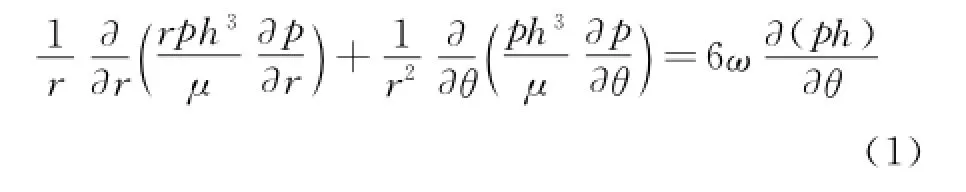
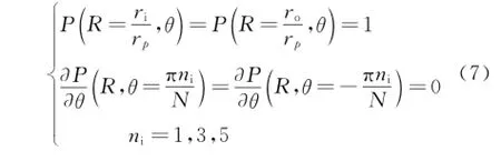
where r andθare the cylindrical coordinates in the radial and circumferential directions,respectively,p the gas film pressure,and h the local film thickness at a specific point.Periodicity of the surface texturing in theθdirection,permits solving the pressure distribution with the following boundary conditions

where riis the inner radius,rothe outer radius,pathe outer radius of the ambient pressure,and N the number of dimple rows on whole ring surface.
The local film thickness,h,between the nominally parallel seal surfaces can be expressed in the following form

whereΩis the studied area.
Eq.(1)is rendered dimensionless by using one dimple radius rpto scale lengths,a nominal clearance h0to scale the local film thickness and pato scale the pressure field,namely

The dimensionless global film thickness,H(R,θ),is given by

Substitution of the dimensionless parameters
into Eq.(1)yields the Reynolds equation in its dimensionless form

The boundary conditions in a dimensionless form are given as
2 Numerical Solution
In order to get film pressure distribution between the two rings,the FD method is adopted to discretize Eq.(6).Fig.3 shows control cells in the present calculation grid system,whereΔR,Δθare the grid sizes in the radial and circumferential directions,respectively.The process can be directed by the method listed as follows

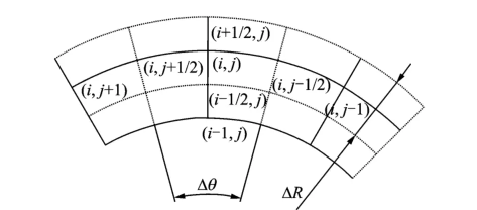
Fig.3 Control cells in calculation grid system
A set of non-linear algebraic equations for the nodal values of the dimensionless pressure,which should be solved with the boundary conditions Eq.(7),are obtained by applying the above method

where A,B,C,D,E,F,G are the discrete coefficients expressed as

The SOR iterative procedure is used to solve Eq.(9).To increase the convergence or to enhance the numerical iterative stability,the method can be expressed as

whereβis the SOR factor,β=1.3.Pki,jis the pressure values at iterative step k at the point(i,j),and Pki,j+1the pressure values at iterative step k+1 at the point(i,j).The convergence condition is taken as

where Errpis the convergence accuracy,chosen as 1.0×10⁻⁵here.
3 Results and Discussion
The calculation is performed for one dimple with diameter 2rp=200μm,hp=6μm,and h0= 5μm.The area density of the dimples is Sp= 31.6%and the angle velocity of the rotorω= 5 000 r/min.The sealed gas viscosity isμ= 1.79×10⁻⁵Pa·s and pa=1.01×10⁵Pa.The dimensionless pressure distribution of single-row column and different multi-row columns is plotted in Fig.4.

Fig.4 Dimensionless pressure distribution of single-row column and multi-row columns
In Fig.4,the pressure profile is not symmetric in the circumferential direction,resulting in positive net pressure build-up.It becomes evident that a hydrodynamic pressure formed on the mechanical gas seal surfaces.The pressure is convergent along the direction of angle velocity of the rotor ring,and in the radial direction,the dimensionless pressure increases nonlinearly with the increase of radius.For different multi-row columns,pressure distribution has the same regularity but the"interaction effect"between two neighboring dimples is clearly different.
For the further investigation of different columns,dimensionless pressure values and the"interaction effect"in different directions are shown in Figs.5—7.
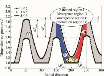
Fig.5 Dimensionless pressure distribution in radial direction of different columns

Fig.6 Dimensionless pressure distribution in circumferential direction of different columns

Fig.7 Dimensionless pressure distribution along circumferential direction of single dimple
Fig.5 presents the dimensionless pressure distribution along the center line of different columns in the radial direction.The pressure value increases as radius expands.For instance,for the 1×5 column,the value from inside to outside of seal surface is 1.951,1.982 and 2.050.For convenience,reference lines 1,2,3 are presented via the second dimple dimensionless pressure peak. The result shows that the maximum dimensionless pressure difference between the 1×5 and the 3×5 columns is.The difference between the 1×5 and the 5×5 columns is.The maximum dimensionless pressures of the 3×5 and the 5×5 columns are close enough.Compared with the 1×5 column,the maximum dimensionless pressure generated by the 3×5 and the 5×5 columns increase by 34.45%and 37.68%,respectively.Similarly,the pressure of the 5×5 column increases by 2.40%compared with that of the 3×5 column. Most significantly,all curves in Fig.5 can be segmented into four regions:the affected region(designated as regionⅠ),the divergence region(regionⅡ)in the descending segment of the curves,the convergence region(regionⅢ)in the increasing segment,and the interaction region(regionⅣ)formed by the"interaction effect",which is produced by the second and the third regions.The"interaction effect"can increase the minimum dimensionless pressurebut the minimum dimensionless pressure of the 3×5 column is very close to that of the 5×5 columnMoreover,compared with the 1×5 column,the minimum dimensionless pressure generated by the 3×5 and 5×5 columns increase by 20.40% and 24.10%,respectively.Similarly,the pressure of the 5×5 column increased by 3.07%,compared with that of the 3×5 column.
In the circumferential direction(Fig.6),the maximum dimensionless pressures generated by the 3×5 and 5×5 columns are 33.55%and 38.86%higher,respectively,than that by the 1×5 column.The minimum dimensionless pressure generated by the 3×5 and 5×5 columns increased by 70.54%and 85.76%,respectively when compared with the 1×5 column.
In Figs.5,6,the dimensionless pressure distributions have the same trends.However,the difference is that the"interaction effect"is more obvious in the circumferential direction becausethe distance of two neighboring dimples is smaller than that in the radial direction.
From the above analysis,these results demonstrate that the dimensionless pressure increases,as calculated by the 3×5 and 5×5 columns. It is necessary to investigate the"interaction effect",especially when the area density of the dimples Spis larger than 20%(see Ref.[23]). Furthermore,the"interaction effect"is more obvious in the circumferential direction than the radial direction even when the area and depth of the dimple are the same.So the"interaction effect"is not inspected(see Ref.[9]and 1×5 column),which is not consistent with the actual working conditions.
Besides the results mentioned above,the simulation also inspects the dimensionless pressure distribution along the single dimple(Fig.2)centerline in different directions(Figs.7,8). Fig.7 shows the dimensionless pressure distribution in the circumferential direction.As depicted in Fig.7,all curves can be divided into three segments,i.e.,the first descending segment,the increasing segment,and the second descending segment.Compared with the 1×5 column,the maximum pressures generated by the 3×5 column and the 5×5 column increase by 33.57% and 38.9 1%,respectively.The minimum pressures generated by the 3×5 and 5×5 columns increase by 78.36%and 85.63%,respectively.As is clearly seen from Fig.7,the offset of different column pressure peaks in the circumferential direction is apparent,ΔD1>ΔD2>ΔD3.ΔD3is very close to the reference line.It becomes evident that the dimensionless pressure investigation calculated by the 5×5 column is more accuracy than that of the 1×5 and 3×5 columns.
Fig.8 presents the maximum dimensionless pressure distribution along the single dimple centerline of different columns in the radial direction.The difference between the 1×5 and 3×5 columns isThe difference between the 1×5 and 5×5 columns isΔP2max= 1.033,and

Fig.8 The maximum dimensionless pressures in radial direction of single dimple
It is clearly seen from the discussion above that each dimple strongly affects its neighboring dimples.This"interaction effect"results in the increase of dimensionless pressure.The increase extents of multi-row columns in different directions are not the same although they have the same area ratio,as well as other parameters. However,the difference between the 3×5 and 5×5 columns is very small.
As an indicator to evaluate the mechanical gas seal surface property,the dimensionless average pressure Pavis chosen as an index to evaluate the load carrying capacity of the whole mechanical gas seal surface.
Fig.9 shows the dimensionless average pressure Pavand the pressure differenceΔPavof different columns.For different columns,the dimensionless average pressures Pavare 1.220,1.647,and 1.774,respectively.The pressure differences areandCompared with the 1×5 column, the dimensionless average pressures Pavgenerated by the 3×5 and 5×5 columns increase by 35.00%and 45.41%,respectively.Similarly,compared with the 3×5 column,Pavof the 5×5 column increases by 7.71%.These results show that the dimensionless average pressure considering the"interaction effect"is larger than that without considering it.Although the increase extents of different multi-row columns are not same,the pressure difference between the 3×5 and 5×5 columns is very small.

Fig.9 Dimensionless average pressure of different columns
4 Conclusions
A hydrodynamic model is developed to investigate the performance for dimpled mechanical gas seal.Circular shape dimples are analyzed.Different multi-row columns with annular area are chosen and the dimensionless pressure considering the"interaction effect"between two neighboring dimples in the radial and circumferential directions is calculated.The following conclusions summarize the results of the present study:
(1)In the radial direction,the dimensionless pressure of different multi-row columns increases because of the consideration of the"interaction effect"between two neighboring dimples. Although the increase is different,the difference of the 3×5 and 5×5 columns is very small.
(2)In the circumferential direction,the dimensionless pressure distribution exhibits the same behavior.However,the"interaction effect"is more obvious than that in the radial direction,even when the area and depth of the dimples are same.It is because the distance of two neighboring dimples in the circumferential direction is smaller than that in the radial direction.
(3)Due to the analysis of the dimensionless pressure of single dimple and the dimensionless average pressure of whole mechanical gas seal surface,it is evident that the 5×5 column with annular area considering the"interaction effect"between two neighboring dimples can be more accurate in predicting the hydrodynamic effect for dimpled mechanical gas seal based on the numerical calculation.
Acknowledgements
This work was supported by the National Natural Science Foundation of China(No.51175246),the Priority Academic Program Development of Jiangsu Higher Education Institutions(PAPD),and the NUAA Research Funding(No.NP2013306).
[1] Wang X L,Kato K,Adachi K,et al.Loads carrying capacity map for the surface texture design of SiC thrust bearing sliding in water[J].Tribology International,2003,36(3):189-197.
[2] Wang X L,Kato K.Improving the anti-seizure ability of SiC seal in water with RIE texturing[J].Tribology Letters,2003,14(4):275-280.
[3] Li J L,Xiong D S,Dai J H,et al.Texture on friction properties of nickel-based composite[J].Tribology International,2010,43(5/6):1193-1199.
[4] Odyckvan D E A,Venner C H.Compressible stokes flow in thin films[J].ASME Journal of Tribology,2003,125(3):543-551.
[5] Zhou F,Kato K.Friction and wear properties of amorphous carbon nitride coatings in water lubrication[J].Transactions of Nanjing University of Aeronautics and Astronautics,2014,31(5):463-477.
[6] Etsion I,Kligerman Y,Halperin G.Analytical and experimental investigation of laser-textured mechanical seal faces[J].Tribology Transactions,1999,42(3):511-516.
[7] Kligerman Y,Etsion I.Analysis of the hydrodynamic effects in a surface textured circumferential gas seals[J].Tribology Transactions,2001,44(3):472-478.
[8] Kligerman Y,Etsion I,Shinkarenko A.Improving tribological performance of piston rings by partial surface texturing[J].ASME Journal of Tribology,2005,127(3):632-638.
[9] Brizmer V,Kligerman Y,Etsion I.A laser surface textured parallel thrust bearing[J].Tribology Transactions,2003,46(3):397-403.
[10]Etsion I,Halperin G,Brizmer V,et al.Experimental investigation of laser surface textured parallel thrust bearings[J].Tribology Letters,2004,17(2):295-300.
[11]Etsion I,Halperin G.A laser surface textured hydrostatic mechanical seal[J].Tribology Transac-tions,2002,45(3):430-434.
[12]Mc Nikel A D,Etsion I.Near-contact laser surface textured dry gas seal[J].ASME Journal of Tribology,2004,126(4):788-794.
[13]Etsion I.State of the art in laser surface texturing[J].ASME Journal of Tribology,2005,127(1):248-253.
[14]Feldman Y,Etsion I.Stiffness and efficiency optimization of a hydrostatic laser surface textured gas seal[J].ASME Journal of Tribology,2007,129(2):407-410.
[15]Nanbu T,Ren N,Yasuda Y,et al.Microtextures in concentrated conformal-contact lubrication:Effects of texture bottom shape and surface relative motion[J]. Tribology Letters,2008,29(3):241-252.
[16]Wang B,Zhang H Q.Numerical analysis of a spiralgroove dry gas seal considering micro-scale effects[J].Chinese Journal of Mechanical Engineering,2011,24(1):146-153.
[17]Lebeck A O.Contacting mechanical seal design using a simplified hydrostatic model[J].Tribology International,1998,21(1):2-14.
[18]Brad A M,Itzhak G.Numerical techniques for computing rotor dynamic properties of mechanical gas face seal[J].Tribology Letters,2002,124(4):755-761.
[19]Marco T C F.An efficient finite element procedure for analysis of high-speed spiral groove gas face seals[J].Tribology Letters,2001,123(1):205-210.
[20]Bonneau D,Huiltric J,Tournerie B.Finite element analysis of grooved gas trust bearing and grooved face seal[J].Tribology Letters,1993,115(3):348-354.
[21]Yu H W,Wang X L,Zhou F.Geometric shape effects of surface texture on the generation of hydrodynamic pressure between conformal contacting surfaces[J].Tribology Letters,2010,37(2):123-130.
[22]Yu H W,Wang X L,Sun Z,et al..Theoretical analysis on hydrodynamic lubrication of cylinder micro-dimple surface texture[J].Journal of Nanjing University of Aeronautics and Astronautics,2010,42(2):209-213.(in Chinese)
[23]Etsion I,Burstein L.A model for mechanical seals with regular microsurface structure[J].Tribology Letters,1996,39(3):677-683.
(Executive editor:Zhang Tong)
TH117.1 Document code:A Article ID:1005-1120(2015)04-0438-08
*Corresponding author:Wang Xiaolei,Professor,E-mail:wxl@nuaa.edu.cn.
How to cite this article:Shi Liping,Huang Wei,Wang Xiaolei.A hydrodynamic model for dimpled mechanical gas seal considering interaction effect[J].Trans.Nanjing U.Aero.Astro.,2015,32(4):438-445.
http://dx.doi.org/10.16356/j.1005-1120.2015.04.438
(Received 3 June 2014;revised 18 October 2014;accepted 24 November 2014)
杂志排行

Transactions of Nanjing University of Aeronautics and Astronautics的其它文章
- Optimization Method for Departure Flight Scheduling Problem Based on Genetic Algorithm
- Dynamic Surface Control with Nonlinear Disturbance Observer for Uncertain Flight Dynamic System
- Control of Vehicle Active Front Steering Based on Active Disturbance Rejection Feedback Controller
- Experiments on an Open-Loop Cycle Carbon Dioxide Refrigeration System
- Resolution Increase and Noise Removal in Particle Size Distribution Measurement with Shifrin Transform
- Real-Time Rendering of Dynamic Clouds Using Multi-Resolution Adaptive Grids