Adjoint-based optimization of flapping plates hinged with a trailing-edge flap
2015-11-21MinXuMingjunWeiChengyuLiHioDong
Min Xu,Mingjun Wei,∗,Chengyu Li,Hio Dong
aNew Mexico State University,Las Cruces,NM 88003,USA
bUniversity of Virginia,Charlottesville,VA 22904,USA
Adjoint-based optimization of flapping plates hinged with a trailing-edge flap
Min Xua,Mingjun Weia,∗,Chengyu Lib,Haibo Dongb
aNew Mexico State University,Las Cruces,NM 88003,USA
bUniversity of Virginia,Charlottesville,VA 22904,USA
A R T I C L E I N F O
Article history:
Received 24 November 2014
Accepted 1 December 2014
Available online 3 February 2015
Flapping wing
It is important to understand the impact of wing-morphing on aerodynamic performance in the study of flapping-wing flight of birds and insects.We use a flapping plate hinged with a trailing-edge flap as a simplified model for flexible/morphing wings in hovering.The trailing-edge flapping motion is optimized by an adjoint-based approach.The optimized configuration suggests that the trailing-edge flap can substantially enhance the overall lift.Further analysis indicates that the lift enhancement by the trailingedge flapping is from the change of circulation in two ways:the local circulation change by the rotational motion of the flap,and the modification of vortex shedding process by the relative location between the trailing-edge flap and leading-edge main plate.
©2015 The Authors.Published by Elsevier Ltd on behalf of The Chinese Society of Theoretical and Applied Mechanics.This is an open access article under the CC BY-NC-ND license(http://reativecommons.org/licenses/by-nc-nd/4.0/).
The unsteady aerodynamic phenomena that allows insects to operate efficiently at low-Reynolds-number is produced by flapping-wing mechanism.The inherently unsteady nature of flapping-wing kinematics is responsible for the primary force production[1],and also differentiates flapping-wing motion fromconventional fixed and rotary wing configurations.In recent years,more attention has been paid to the aerodynamics of deformable wings[2,3].Results have revealed that the dynamically changed wing surface,either actively or passively deformed,would potentially provide new aerodynamic mechanisms[4]of force productions over completely rigid wings[1,5]in flapping flights.The performance of a rigid wing can be significantly improved by adding chord-wise flexibility onto the wing.Vanella et al.[6]used a 2-D two-link model to model the chord-wise flexibility in a flapping plate.It shows that if appropriately chosen,the chord-wise flexibility can result in up to 28%enhancement in terms of lift-todrag ratio and 39%increase for lift-to-power ratio comparing to a rigid one.In addition,Wan etal.[7]investigated the effectofchordwise flexibility over a range of hovering kinematics parameters using a hinged-plate model.Their results indicated that higher liftto-drag ratio can be obtained by hinging the plate at three-quarter chord from the leading-edge comparing to a fully rigid plate in the same flapping kinematics.Li et al.[8]performed numerical simulations of deformable flapping plate by attaching a trailing-edge flap(TEF)and studied its effects on aerodynamic performance and flow modulation.Results have shown that the optimal lift production can be achieved by tailoring the trailing-edge deflection angle and phase shift.The enhancement of lift production is up to 26% comparing to a completely rigid flapping plate.
However,if the parameter space of the problem is further increased,it is impracticable to find the optimal setting via direct parametric case study.Adjoint-based optimization,on the other hand,offers the same computational efficiency for increased number of control parameters[9-11].In this work,we have developed an adjoint-based approach to quickly find the optimal solution of chord-wise wing morphing.The further analysis of the optimal solution allows us to study the effect of wing flexibility through its comparison to rigid and other configuration not optimized for aerodynamic performance.The rest of the paper is arranged in the following manner.The governing equations and numericalsimulation details are first introduced.Then,the optimization results are discussed.The conclusion is given at the end.
Shown in Fig.1,the configuration of the flapping plates is chosen to be the same as the one used by Li et al.[8],which allows a convenient comparison of performance and accuracy from different approaches.The leading-edge(i.e.main)plate and the trailingedge plate are respectively 0.75 and 0.25 based on the total length. The flapping motion is prescribed by

where AL=3 andβL=45◦are respectively the amplitudes of the leading-edge plate's horizontal and rotational motion,and f=1/(3π)is the flapping frequency.All the variables are nondimensionalised by the total chord-length c and the reference velocity Uref=πfAL.The control parameters are the flapping amplitudeβTand the phase delayϕTof the trailing-edge flap.The two parameters are optimized to achieve the maximum lift.The Reynolds number,Re=Urefc/ν,is 100 for all the cases.Here,we only considerthe periodic state,which can be achieved after8 flapping cycles.
The surrounding flow satisfies the incompressible Navier-Stokes equations

with convective boundary conditions at the far field,and the Dirichlet condition along the solid wing surface S

where Viis the local velocity of solid.
Staggered Cartesian mesh with local refinement through stretching is used to provide both efficiency and numerical stability.Immersed boundary method[12,13]is implemented for the description of moving solid boundaries(i.e.hinged plates)in both the forward simulation of fluid flow and the backward simulation of the adjoint field.The second-order central difference scheme is used for spatial discretization and the third-order Runge-Kutta/ Crank-Nicolson scheme is used for time advancement[14-16].The continuity equation for incompressible flow is enforced by projection method[16].
The computationaldomain has non-dimensionalsize 30×30.A stretched 290×320 Cartesian mesh is used for an overall Eulerian description of the combined fluid and solid domain.The grid is clustered near solid region with a minimum size ofΔx=Δy= 0.02.There are 202 marker points for the Lagrangian description of the moving hinged plates with zero thickness.

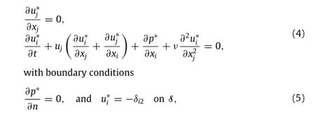

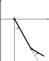
Fig.1.Schematic of a flapping plate hinged with a trailing-edge flap.


where

and Siis the location of the solid point,niis the norm direction from solid to fluid and T is the time for one flapping cycle.The control is updated along the gradient to eventually converge to an optimalsolution.The accuracy ofthe gradientcomputed by adjoint approach has been validated in our earlier work,and there are also details on derivation[14,15].
The optimization is started with an arbitrarily chosen initial control,φ0=(20◦,-40◦).It is shown in Fig.2 that,after 6 iterations,the lift coefficient is improved by 18.7%,from 0.793 to 0.941. Three cases are compared in Table 1:(a)the rigid plate without trailing-edge flap,(b)the initial control,and(c)the optimal control,which are consistent with the choices of the direct parametric study by Li et al.[8].The outcome of the adjoint-based optimization also matches very wellwith the direct parametric study.However,it is worth noting that the adjoint-based optimization(with 6 iterations)has much lower computational cost than the direct approach(with 72 cases).More important,the computational cost from the adjoint-based approach,by its nature,should remain at about the same level as the control parameters increase from 2 to a much larger number(e.g.more than 10);on the other hand,such increase of control parameters will lead to much larger(or impossible!)computational cost from the direct approach through the increase of cases to cover a much larger parametric space[14].
The optimal control provides much higher lift coefficient than the rigid case with 27%enhancement,though the initial control also provides lift enhancement by 7.3%from the rigid case.It is shown in Fig.3 that,during one single flapping circle(8T≤t<9T),the major lift enhancement happens at t=8.2T and t=8.8T.At these two moments,as shown in Fig.4,the instantaneous translational velocity at the leading edge,vxL=d xL/d t reaches its maximum amplitude(positively or negatively).
In current study,the plates do not interact with their own wake during flapping due to the strong downwash velocity induced by high lift.Therefore,despite the unsteadiness,quasi-steady model can still be a good approximation[19,20]and help to interpret the complex results.It is worth noting that the coefficients of quasisteady model are computed from numerical simulation data.The numerical simulation and optimization still rely on direct numerical simulation approach mentioned above.

Table 1The lift coefficients for the rigid flapping plate and hinged flapping plates with initial and optimized controls.
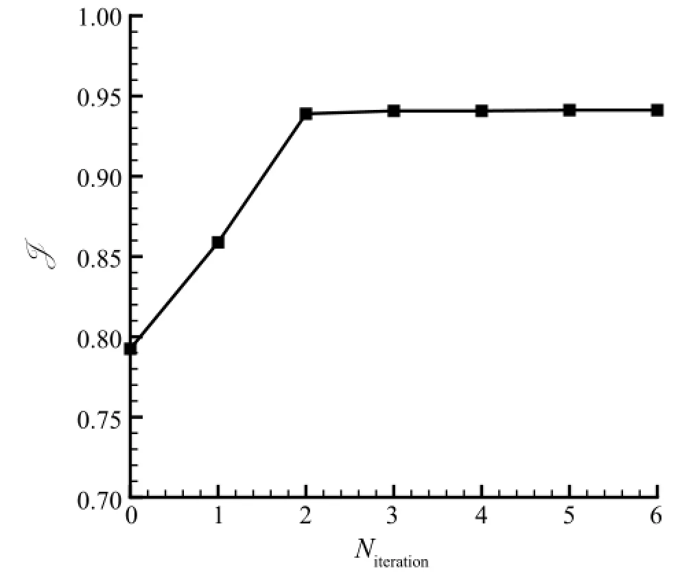
Fig.2.The optimization process showing the change of the cost function(i.e.lift coefficient)by the number of iterations.
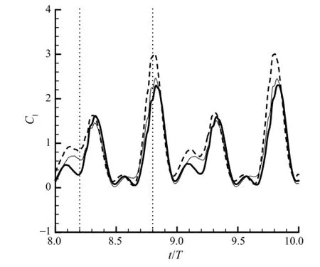
Fig.3.Comparison of the lift coefficients for the case of a rigid flapping plate(thick solid line),the case of hinged plates with the initial control(thin solid line),and the case of hinged plates with the optimized control(dashed line).Two moments,t=8.2T and t=8.8T,are marked by dotted lines for better comparison.
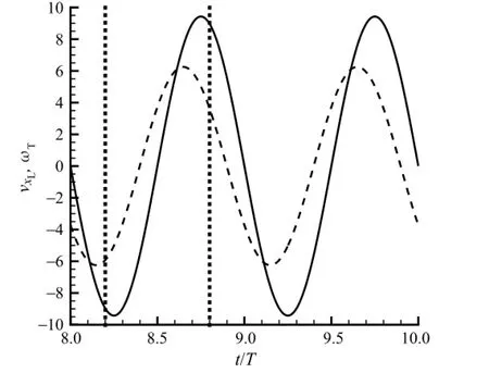
Fig.4.The time variation of the translationalvelocity vxL(solid line)ofthe leadingedge and the angular velocityωT=dθT/d t(dashed line)of the trailing-edge flapping with the optimized control.Two moments,t=8.2T and t=8.8T,are marked by dotted lines for better comparison.
According to the quasi-steady model,the circulation component of the total lift is

whereΓis the circulation along the plates and is defined to be positive for anti-clockwise vortices.The formulation(8)implies that the lift is more sensitive to the change of circulation at the moment when the translational velocity vxLhas large amplitude.For our case,it means the two moments t=8.2T and t=8.8T.
The trailing-edge flap changes the circulation(and eventually the lift)through two ways:(1)the rotational motion of the flap itselfchanges directly the totalcirculation;(2)the angle between the main plate and the trailing-edge plate changes the shedding process of the trailing-edge vortex(TEV)which,in turn,has a negative impact on the total circulation through the conservation of angular momentum.Both effects can be observed in Fig.5.At t=8.2T,when vxL<0,the clockwise flapping motion of the flap brings in additional negative circulation,therefore,it increases the overall lift;at t=8.8T,when vxL>0,the additional positive circulation by the anti-clockwise motion of the flap results also the overall lift enhancement.The optimal flow at both time moments also show stronger TEV shedding in comparison to the rigid case and the initial case.The stronger vortex shedding leads to larger lift at these moments.
We numerically studied the impact of wing flexibility/morphing towards the aerodynamic performance(i.e.lift coefficient in the current work)of flapping wings in hovering motion.The study is based on a simplified model,a flapping plate hinged with a trailing-edge flap.A newly-developed adjoint-based approach is used to reach the same optimal setting but much lower computational cost compared to a previous study using direct parametric case study.It is noted that the current extension of using adjoint-based approach on moving-boundary problems has only become possible through the introduction of non-cylindrical calculus to handle the boundary derivatives for the derivation of adjoint equations.
Through the comparison between the rigid(i.e.no hinged flap)case and the optimal trailing-edge flapping case,we see a 27%lift enhancement.Further analysis shows that the lift enhancement is the result of circulation changes at the moment when maximum translational speed of the leading edge happens.The implementation of a trailing-edge flap at its optimal rotation and phase delay results in the increase or decrease of the circulation at those critical time moments.The change of circulation,the maximumtranslational speed of the leading edge,and the right sign of both values,together,result in the lift enhancementin the currentstudy. In other words,the impact of the trailing-edge flap to the lift enhancement is through the change of circulation by both the rotational motion and the relative angle of the two plates.
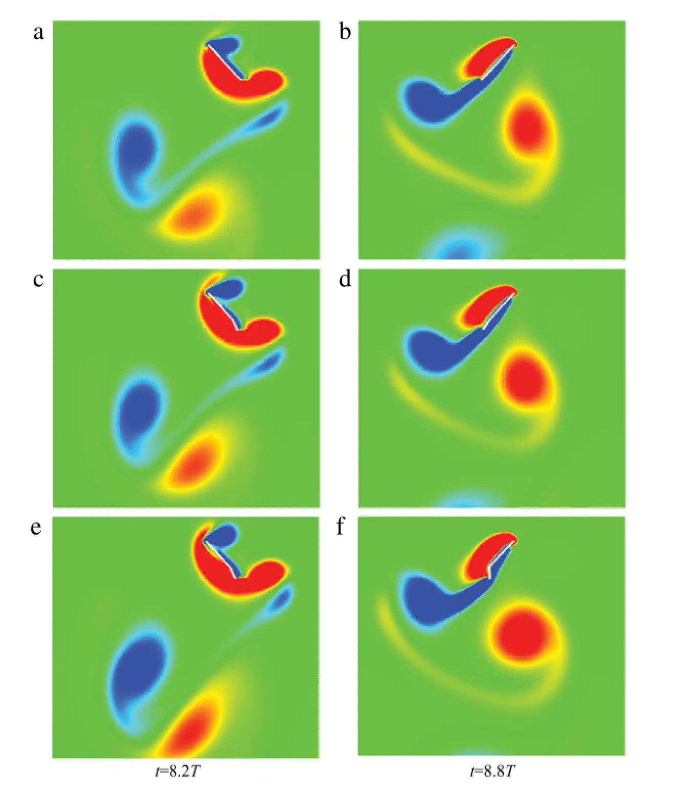
Fig.5.(Color Online)The flow field marked by vorticity contours at two time moments t=8.2T and t=8.8T:(a)and(b)are the case of a rigid flapping plate;(c)and(d)are the case of hinged flapping plates with the initial control;(e)and(f)are the case of hinged flapping plates with the optimal control.The red and blue colors respectively denote anti-clockwise and clockwise vortices.
Acknowledgment
This work was supported by AFOSR(FA9550-12-1-0071).
[1]M.H.Dickinson,F.O.Lehmann,S.P.Sane,Wing rotation and the aerodynamic basis of insect flight,Science 284(1999)1954-1960.
[2]J.Valasek,Morphing Aerospace Vehicles and Structures,John Wiley&Sons,Chichester,2012.
[3]H.Wang,L.Zeng,H.Liu,C.Yin,Measuring wing kinematics,flight trajectory and body attitude during forward flight and turning maneuvers in dragonflies,J.Exp.Biol.206(2003)745-757.
[4]W.Shyy,Y.Lian,J.Tang,D.Viieru,H.Liu,Aerodynamics of Low Reynolds Number Flyers,Cambridge University Press,New York,2008.
[5]M.Sun,J.Tang,Unsteady aerodynamic force generation by a model fruit fly wing in flapping motion,J.Exp.Biol.205(2002)55-70.
[6]M.Vanella,T.Fitzgerald,S.Preidikman,E.Balaras,B.Balachandran,Influence of flexibility on the aerodynamic performance of a hovering wing,J.Exp.Biol. 212(2009)95-105.
[7]H.Wan,H.Dong,G.P.Huang,Hovering hinge-connected flapping plate with passive deflection,AIAA J.50(2012)2020-2027.
[8]C.Li,H.Dong,Y.Ren,A numerical study of flapping plates hinged with a trailing-edge flap,AIAA Paper 2014-2049(2014).
[9]A.Jameson,Aerodynamic shape optimization using the adjoint method. Lectures at the Von Karman Institute,Brussels,Febuary 6(2003).
[10]T.R.Bewley,P.Moin,R.Temam,DNS-based predictive control of turbulence: an optimal benchmark for feedback algorithms,J.Fluid Mech.447(2001)179-225.
[11]M.Wei,J.B.Freund,A noise-controlled free shear flow,J.Fluid Mech.546(2006)123-152.
[12]R.Mittal,H.Dong,M.Bozkurttas,F.Najjar,A.Vargas,A.VonLoebbecke,A versatile sharp interface immersed boundary method forincompressible flows with complex boundaries,J.Comput.Phys.227(2008)4825-4852.
[13]T.Yang,M.Wei,H.Zhao,Numericalstudy offlexible flapping wing propulsion,AIAA J.48(2010)2909-2915.
[14]M.Xu,M.Wei,A continuous adjoint-based approach for the optimization of wing flapping,AIAA Paper 2014-2048(2014).
[15]M.Xu,M.Wei,Using adjoint-based approach to study flapping wings,AIAA Paper 2013-0839(2013).
[16]H.Zhao,J.B.Freund,R.D.Moser,A fixed-mesh method for incompressible flow-structure systems with finite solid deformations,J.Comput.Phys.227(2008)3114-3140.
[17]M.Moubachir,Moving Shape Analysis and Control:Applications to Fluid Structure Interactions,CRC Press,Abingdon,2006.
[18]B.Protas,W.Liao,Adjoint-based optimization of PDEs in moving domains,J.Comput.Phys.227(2008)2707-2723.
[19]A.Andersen,U.Pesavento,Z.Wang,Unsteady aerodynamics of fluttering and tumbling plates,J.Fluid Mech.541(2005)65-90.
[20]G.J.Berman,Z.J.Wang,Energy-minimizing kinematics in hovering insect flight,J.Fluid Mech.582(2007)153-168.
∗Corresponding author.
E-mail address:mjwei@nmsu.edu(M.Wei).
Trailing-edge flap
Adjoint-based optimization
*This article belongs to the Fluid Mechanics
杂志排行
Theoretical & Applied Mechanics Letters的其它文章
- Numerical simulation of unsteady flows over a slow-flying bat
- Propulsive performance of two-and three-dimensional flapping flexible plates
- Learning from bat:Aerodynamics of actively morphing wing
- A coupled immersed boundary-lattice Boltzmann method and its simulation for biomimetic problems
- A modified criterion for wave-induced momentary liquefaction of sandy seabed
- Vortex interactions between forewing and hindwing of dragonfly in hovering flight
