Simulation of phased array S-scan acoustic field in FSW joint of alum inum alloy extrudate w ith com p lex shape*
2015-09-05WangChangxiandGangTie王常玺
Wang Changxi and Gang Tie王常玺,刚 铁**
Simulation of phased array S-scan acoustic field in FSW joint of alum inum alloy extrudate w ith com p lex shape*
Wang Changxi and Gang Tie
王常玺,刚 铁**
The shape of aluminum alloy extrudate used in high-speed train is complex,structural noises from the surfaces of the extrudate will be received when using ultrasonic phased array to detect the flaws in FSW.To solve this problem,ultrasonic phased array acoustic field model and propagation simulation of acoustic waves were introduced to simulate the acoustic pressure distribution and the propagation of the acoustic waves.With themethods above,the detection parameters can be optimized and as a result,the experimental process can be simplified and the detection efficiency can be improved.Meanwhile,the echoes in the S-scan images can be predicted,which can help analyze the detection results and judge the defects.
aluminum extrudate,phased array,acoustic field simulation,FSW
0 Introduction
Aluminum alloy extrudate is widely used in highspeed trains.The shape of extrudate is complex and as a result,it is hard to detect the defects inside with conventional NDTmethods.
The ultrasonic phased array technology has advantages such as electronic scanning and can improve detection efficiency.However,since the shape of extrudate used in high-speed train is complex,the acoustic pressure distribution is hard to know.So it is necessary to establish proper acoustic simulation field to obtain reliable results. Sha ZX et al.simulated the radiated acoustic field of ultrasonic transducers and made it visualized by means of multi-Gaussian wave model[1].The experimental results demonstrated that the simulation can represent the distribution of the acoustic field actually and exactly.Ming D et al.proposed an approach to simulate the acoustic field of linear phased array using spatial pulse response[2].This approach does not need far-field approximation.Themethod is of potential to help design NDT system,and could be used in two-dimensional array transducers as well.Kurozumi Y et al.found that dual-element probes were sufficient to remove dead zone of the detection zone[3-4]and the simulation results verified this.Y Luo et al.established amathematicalmodel for phased array based on orthotropic piezoelectric compositematerials(OPCM)actuator by analyzing the principle of orthotropic construction[5].The simulation results showed that the effects on directivity were in good coincidence with the focus of acoustic field,and the focus energy increased highly due to its unique orthotropic design.A.D.Cinson etal.drew the actual acoustic field of the outer surface of a stainless steel tube by placing a transmitting probe inside the tube and moving a receiving probe along the entire outer surface of the tube[6].From the acoustic field drawn,the influence of coarse grains in the coarse-grained stainless steel on the ultrasonic phased array acoustic wave propagation was obtained,which provided guidance for developing amore effective detection method.
However,the simulations above are all based on the premise that acoustic waves propagated in infinite space. Usually the workpieces have complex shapes,which means the acoustic field inside thewelds is complex and so are the propagation paths of thewaves.To solve this problem,in this paper acoustic field simulation and simulation of propagation of acoustic waves were conducted on weldsof extrudate and the results were discussed.
1 Acoustic field simulation
1.1Simulation condition
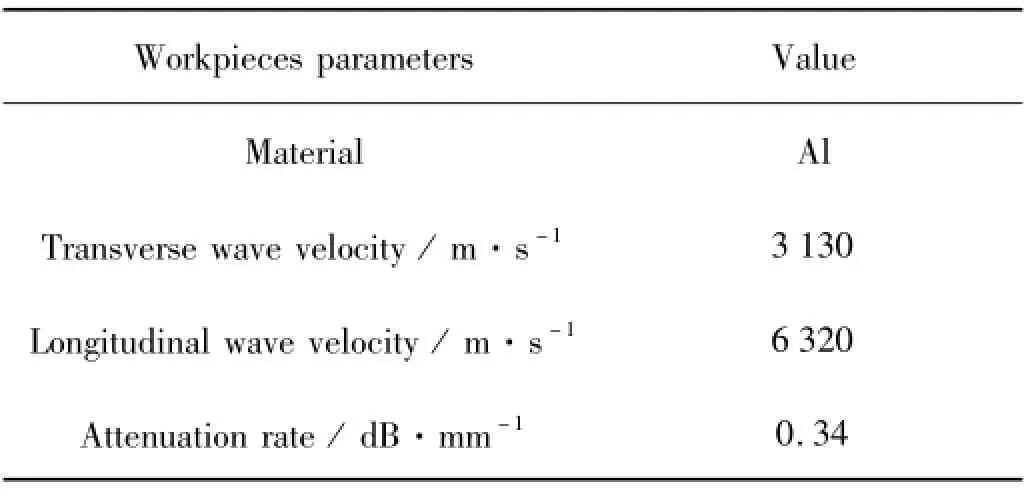
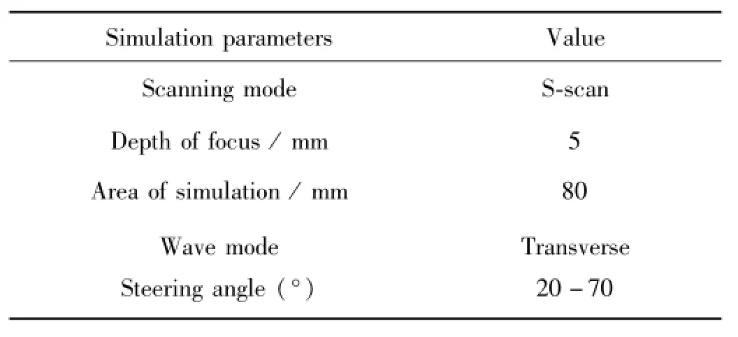
The characteristics of acoustic pressure distribution can be obtained by means of simulation,including the focusing effect of the waves,the deflection angle and the coverage of focusing points etc.It is necessary to help determine suitable detection parameters and carry out the experiments efficiently.The original shape of the simulation model is shown in Fig.1.The parameters of probe and workpieces in simulation are shown in Table 1 and Table 2.

Fig.1 Cross-sectional view of a kind of alum inum alloy extrudate used in high-speed train

Table 1 Parameters of workpieces in simulation

Tab le 2 Sim ulation and experimental parameters
1.2Sim ulation resu lts

Fig.2 The typical acoustic field simulation results
The acoustic field simulation results are shown in Fig.2,and the parameters used in simulation are shown in Table 3.From Fig.2,the acoustic field simulation results show that the focusing effect was satisfactory when the acoustic waves in the extrudate were inclined.The color of focus is purple,indicating the highest acoustic pressure. By correctly setting the electronic scanning parameters,the acoustic waves swung inside the extrudate and can ef-fectively cover the entire weld area.Moreover,the focus just appeared where it was set.The focusing effect was worse when the acoustic wave angle is large(Fig.2d)and the focusing effect is better when the wave angle is small (Fig.2b).But if the acoustic wave angle was too small,the defects perpendicular to the surface ofworkpieces were hard to detect because there were sidelobes.The reason was that the smaller incidentangle led to relatively smaller difference between the refraction angle of transverse and longitudinal waves.As a result,interference occurred which disturbed the original acoustic field.Based on the analysis above,the acoustic wave angle should be controlled within the range from 30°to 60°.
Because the cross-sectional geometry is complex,there were irregular acoustic field reflections caused by the influence ofmultiple complex interfaceswhen the acoustic waves propagated.According to Fig.2a,the acoustic wave incident rays coming from B side will be reflected by the air gap between the extrudate and the corners of the extrudate.So it can be inferred that there will be echoes in extrudate corners and defects where the acoustic field covers.It is noted that the air gap between the extrudate A and B stops the acoustic waves from propagating further,so there is an area whose acoustic pressure is almost zero.

Table 3 Parameters used in simu lation
2 Acoustic rays p ropagation sim u lation
2.1Propagation simulation of acoustic waves in weldsw ithout defects
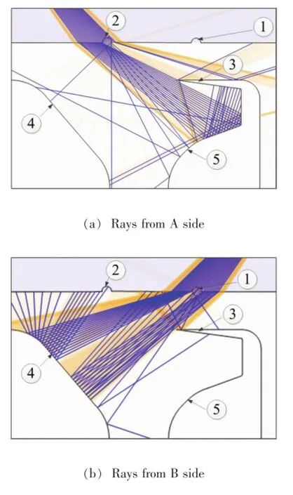
In order to further understand the propagation paths of the ultrasonic waves in extrudates and the influence of FSW weld flash on detection,propagation simulation of acoustic waves in weldswas conducted.It can help predict the reflection situation and the imaging situation when the acoustic rays reflect on defects and various parts of the structure.Meanwhile,the characteristic points can also be determined,which can help analyze the detection results.
According to Fig.3,there are five locationswhere reflectionsmay occur.Of the five locations,1 and 2 are weld flashes,3 is the air gap between extrudate A and B,4 and 5 are fringes of the extrudate.When incident rays came from A side,therewere reflections in parts2,3 and 5.Reflections from 3 were not received by probe,in comparison;reflections from 2 and 5 can be treated as the characteristic points.Similarly,when incident rays came from B side,reflections from 1 and 4 could be treated as the characteristic points which may help distinguish the defects.

Fig.3 Propagation simulation of acoustic waves in weldswithout defects
2.2Propagation simulation of acoustic waves in welds w ith defects
Defects tend to occur during the welding process.To make the simulation more real,in Fig.4,defect 6 was added to the weld.It is a kind of unfused defectwhich e-merges frequently.By the contrast of propagation simulation of acoustic waves in welds,it can be concluded that when the incident rays came from A side,the reflected waveswould not go back to the probe,butwhen the incident rays came from B side the defect and the air gap formed a corner and the reflected waves were strong.So it was easier to detect unfused defects when incident rays came from B side,meanwhile,1 and 4 were the characteristic points.

Fig.4 Propagation simulation of acoustic waves in welds w ith defects
3 Experim ental resu lts
To verify the reliability of the above simulation results,real S-scan detection was carried on two aluminum extrudate workpieces.The acoustic wave angleswere chosen between 30°and 60°and the focus depth was set at 5mm,the thickness of the plates of B side.The results are shown in Fig.5 and Fig.6 respectively.According to Fig.5,when the incident rays came from A side,reflections in flash 2 and the fringe of the extrudate 5 could be observed,which corresponded to the simulation results in Fig.3a.When incident rays came from B side,correspondingly therewere obvious reflections in flash 1 and the fringe of the extrudate 4,which was in agreementwith the simulation results in Fig.3b.The S-scan area could be located easily in the image based on the characteristic points above and then the defects can be determined rapidly.The S-scan images were all consistent with the simulation results.

Fig.5 S-scan results of welds w ithout defects
Fig.6a and Fig.6b show the S-scan images of the butt joints when incident waves come from A and B side separately.As shown in the two images,there were no echoes of defects when incident rays came from A side,which is the same with that in Fig.5a.Meanwhile there were non-structural echoes(position 6 in Fig.6b)whenincidentwaves came from B side,which is obviously different from that in Fig.5b.Themetallographic pictures of the welds with and without defects are shown in Fig.7. From Fig.7c,it can be seen there was a hook defect in the center of the metallographic macrostructure picture. The defect can be observed more clearly from themetallographic microstructure picture Fig.7d.In Fig.7b,a horizontal air gap can be seen in the metallographic microstructure image.The shape of the defect was similar to a hook and therefore the corner-echo was strong when incident waves came from the orientation of the defect(B-side).In comparison,there was no corner-echo when in-cidentwaves came from A side(Fig.6a).Fig.7e shows the formation of the hook.The upper portion of the vertical air gap is directly welded by the needle,while the lower portion of the vertical air gapmoveswith the flow of the aluminum and together with the horizontal air gap,a hook forms.The zigzag lines in Fig.7b and Fig.7d are boundaries ofmicrostructures and there are no ultrasound echoes from these boundaries.The S-scan results verified the accuracy of the acoustic wave simulation in Fig.4.It is noteworthy that there were echoes outside the profile of the extrudate in Fig.5 and Fig.6,which are caused by the diffraction ofwaves.

Fig.6 S-scan results of weldswith defects

Fig.7 M etallographic pictures of FSW welds and cause of the defect
Based on the experimental results above,the S-scan imagesmatched the simulation results well,which means the structural echoes predicted in propagation simulation of acoustic waves in welds could be represented in the S-scan image.Meanwhile,the simulation results can explain why the S-scan images of the same defect with the shape of hook were differentwhen incidentwaves came from opposite sides,which was of significance to the prediction and explanation of the real detection results.
4 Conclusions
(1)The effect of focusing and acoustic wave deflection in the aluminum extrudate weld can be visualized easily by means of simulation.This is helpful to determine the suitable focus depth and acoustic wave deflection angle in practical detection and is time-saving.
(2)Propagation simulation of acoustic waves in welds can effectively show the paths of acoustic waves in the extrudate and can help predict the echoes in the S-scan images,which is helpful to obtain the characteristic points of S-scan images and facilitate the analysis of the images.
References
[1] Sha Z X,Gang T,Zhao X Y.Simulation and visualization of the radiated acoustic field of ultrasonic transducers.Nondestructive Testing,2011(5):2-6.(in Chinese)
[2] Ming D,HongweiM,Yuan C.A method to simulate acoustic field of a linear phased array transducer.Measuring Technology and Mechatronics Automation(ICMTMA),2013 Fifth International Conference on.IEEE,2013:33-36.
[3] Kurozum i Y.Development of an ultrasonic inspection technique for cast stainless steel.Insight,2002,44(7):437-442.
[4] Mahaut S,Godefroit J L,Roy O,et al.App lication of phased array techniques to coarse grain components inspection.Ultrasonics,2004,42(1):791-796.
[5] Luo Y,Wang Z.The focus acoustic field simulation based on parameter optimization of OPCM ultrasonic phased array elements.Piezoelectricity,Acoustic Waves,and Device Applications(SPAWDA)and 2009 China Symposium on Frequency Control Technology,Joint Conference of the2009 Symposium on.IEEE,2009:46.
[6] Cinson A D,Crawford S L,Prowant M S,et al.Ultrasonic phased array sound field mapping through large-bore coarse grained cast austenitic stainless steel(CASS)pipingmaterials.SPIE Smart Structures and Materials+Nondestructive E-valuation and Health Monitoring.International Society forOptics and Photonics,2012:83471A-83471A-11.
*Thiswork was supported by the National Natural Science Foundation of China(Grant No.51175113).
**Wang Changxi and Gang Tie,State Key Laboratory of Advanced Welding and Joining,Harbin Institute of Technology,Harbin,150001. Gang Tie,Corresponding author,E-mail:gangt@hit.edu.cn
杂志排行
China Welding的其它文章
- A Fe-Ni-Cr system filler metal for brazing of stainless steel*
- Numerical analysis of thermal process in continuous drive radial friction welding*
- Effect of refilling time on Microstructure and Mechanical properties of friction spot welded LY12 alum inum alloy*
- Mechanical and corrosion properties of 445J2 ultra pure ferritic stainless steel joint*
- Simulation on the deformation controlling of T-joint LBW w ith auxiliary heat source for high strength alum inum alloy*
- Analysis of grain grow th in hybrid weld HAZ based on the coupled thermo-fluid model
