Numerical analysis of thermal process in continuous drive radial friction welding*
2015-09-05QinGuoliangLiangYongliangGengPeihaoWangYanandZhouJun秦国梁梁永亮耿培皓
Qin Guoliang,Liang Yongliang,Geng Peihao,Wang Yan and Zhou Jun秦国梁,梁永亮,耿培皓,王 严,周 军**
Numerical analysis of thermal process in continuous drive radial friction welding*
Qin Guoliang,Liang Yongliang,Geng Peihao,Wang Yan and Zhou Jun
秦国梁,梁永亮,耿培皓,王 严,周 军**
A heat sourcemodel for radial friction welding was proposed,which was determined by friction pressure,friction coefficient,material propertiesand extrusion speed of material.A 3D model was established to analyze the continuous drive radial friction welding temperature field of45 steel pipe.The influencesof friction pressure,friction timeand rotation speed on the temperatureof the friction interfacewereanalyzed.The resultsshowed that the temperatureon the friction interface rapidly rose to a peak temperature in initial friction stage and kept constant in the stable friction stage.Welding parametersof friction pressure,friction time and rotation speed had few influences on the peak temperature,while the increase of friction pressure and rotation speed could shorten the time to reach the peak temperature.
radial friction welding,heat sourcemodel,temperature field,thermal cycle
0 Introduction
Radial friction welding(RFW)is one of solid state weldingmethods for pipe joining.Conventional rotary friction welding requires that one pipe is rotated to generate friction heat,but using RFW both pipes remain stationary. The RFW technique involves rotation and radial compression of a solid beveled ring into a V groove formed at the pipe ends to be joined.To prevent collapse of the pipe ends,an internal supportmandrel isneeded at the welding position.In the mid 1970s and 1980s,a dedicated RFW machinewas designed and built to join pipeswith different dimensions[1].In recent years,the copper alloy belt had been bonded on the steel pipe by radial friction welding.
The thermal cycle in friction welding can determine the welding quality,which depends on the welding parameters such as friction pressure,friction time,and rotation speed and the properties of material[2].The numerical simulation method is mostly used to study the friction welding temperature field.Deng et al.established a 2D model for RFW of shell band,in which the complex friction-heat generation was simplified to an average heat flux in order to effectively obtain the temperature field and the stress field[3].Hu et al.and Wang et al.optimized the clampingmodel of the RFW by 3D finite elements analysis[4].Wang et al.proposed a heat inputmodel based on the Coulomb's law of friction[5].Zhang et al.researched the thermo-mechanical coupling in RFW process of 45 steel by establishing a 3D model based on ABAQUS software[6].
A numericalmodelwas founded to study the temperature field and heat generation of friction interface in the RFW process of 45 steel at different welding parameters,which can help to understand the thermal process of RFW.
1 Experimental
The temperature measurement system was founded based on semi-natural thermocouple by taking 45 steel wire and NiSiwire as positive pole and negative pole,re-The temperatures at the friction interface and other positions of 1mm,2mm,3mm and 6mm below friction interface in the steel pipe weremeasured and used to verify the calculation results,the peak temperatures at different positions are shown in Fig.3.
*Thiswork was supported by National Natural Science Foundation of China(Grant No.51075174/E050803).
**Qin Guoliang,Liang Yongliang,Geng Peihao and Wang Yan,MOE Key Laboratory for Liquid-Solid Structural Evolution and Processing of Materials,and Institute of Materials Joining,Shandong University,Jinan,250061. Zhou Jun,Harbin Welding Institute,Harbin,150028. Qin Guoliang,Corresponding author,E-mail:glqin@sdu.edu.cnspectively.Its schematic diagram is shown in Fig.2.
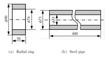
Fig.1 Dimensions of 45 steel radial ring and pipe
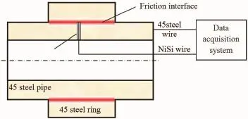
Fig.2 Princip le of sem i-natural thermocoup le to measure temperature in radial friction welding process
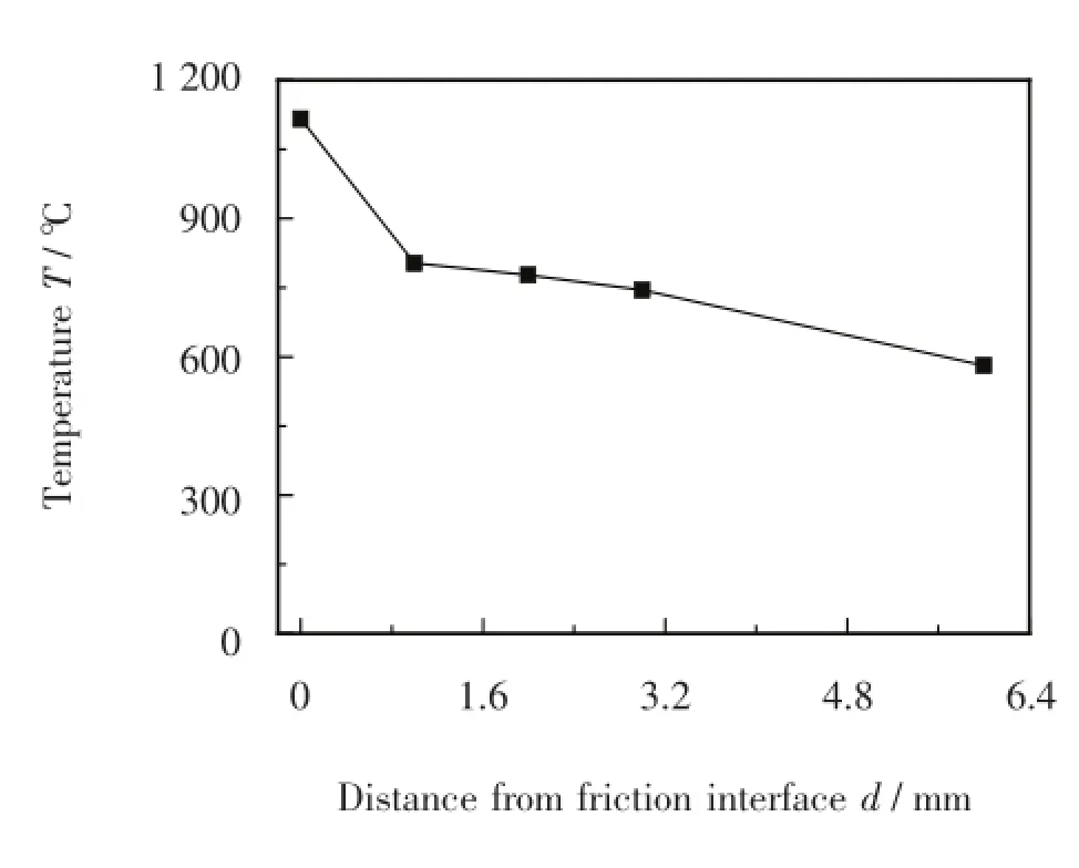
Fig.3 Peak temperature at different positions tested in radial friction welding process
2 Modeling
Radial friction welding process is a complex thermalmechanical coupling process with friction heat generation and plastic deformation under the friction pressure.The material on the friction interface reaches thermoplastic state and begins to flow with temperature increasing rapidly and is extruded out from the friction interface under the upsetting pressure.In order to simplify the calculation,several hypotheses were proposed as follows.
(1)During the friction welding process,friction heat is themain heat source compared with plastic deformation energy which is ignored in thismodel.
(2)The welding heat input is generated in a thin layer during the radial friction welding process.
(3)The heat loss by the extrudedmaterial is associated with the heat generation.
2.1Geom etry model
The combined structure is shown in Fig.4a which is composed of ring,pipe,support mandrel,and clamps. The structure is axisymmetric,which possesses the same heat generation mechanism in every part of the radial ring. In order to save the computing time,1/20 of the structure in the circumferential direction is taken for finite element analysis.The eight-node thermal element SOLID70 is used and SWEEPmethod is used to mesh the model.The element size of heat generation layer,pipe,ring and clamp are 0.5mm,1mm,1mm and 1.8mm,respectively.The meshing result is shown in Fig.4b.

Fig.4 Geometrymodel of radial friction welding
2.2 Heat source model
The Coulomb's law of friction is used to calculate the heat flux.It isassumed that the heat is generated and uniform ly distributed in a very thin layer called friction layer. The heat flux can be described as follows:
where q is the heat flux,R is the radius of the friction interface,ηis the heat generation efficiency,μis the friction coefficient,n is the rotation speed,pnis the radial pressure,c is the specific heat capacity,ρis the material density,T is the temperature when the material is extruded from the friction layer,T0is the ambient temperature,vsis the radial shortening rate,h is the thickness of the friction layer.
As shown in Eq.(1),the heat flux is determined by the friction parameters and the material properties.According to the previous studies[7-8],both the specific heat capacity and yield strength are dependent on the temperature,they are fitted as follows,respectively:

The Coulomb friction model is used to describe the friction behavior in radial friction welding process.The sliding friction coefficient is related to the relative velocity,friction pressure and temperature of the friction interface.In this study,the temperature-dependent friction coefficient is fitted based on the data from reference[6]:

2.3 Governing equation and boundary conditions
This study principally focuses on the calculation of temperature distribution and thermal cycle through developing a friction heat source model.To speed up the calculation process,only the heat conduction in the transient state is considered and the plastic flow near friction interface is ignored.
The nonhomogeneous Fourier heat conduction equation is given as follows:

On the surfaces of pipe and ring,the third boundary condition should be satisfied:

whereλis heat conduction coefficient,is the temperature gradienton the boundary,a is heat transfer coefficient of air,a=20W/(m2·℃),Tbis the temperature on the boundary,and the room temperature T0is 20℃,respectively.
The initial condition is given as:

In this study,a feedback loop calculation method is used to run the program,in which the average temperature T of the nodes on friction layer is extracted and substitutes the equations of heat sourcemodel.The state ofmaterial is also evaluated by comparing the value of friction pressure and the value of yield strength.If the friction pressure is higher than the yield strength of themetal,then the friction pressure will be changed to the yield strength and the metal extrusion will be initiated in the program.
3 Results and discussion
The continuous drive radial friction welding process can be divided into three stages of initial friction stage,stable friction stage,and upsetting stage.The influences ofwelding parameters on the continuous drive radial friction welding thermal process are studied.The pressures and friction time in three stages are set based on experimental measurement,respectively.In calculation,the friction heatgeneration efficiencyηis set as 0.9.
3.1Temperature Field
The calculated temperature distribution is shown in Fig.5.The temperature on the friction interface is the highest,and the further away from the friction interface the position is,the lower the temperature is.In radial direction,the isotherm is distributed as a series of concentric circles.In the last stage of radial friction welding process,the fixture and supportmandrel have higher temperature because of heat conduction.
The highest temperature on the friction interface reaches up to 1 200℃at3 swhen the initial friction stage is over.Comparison of the temperature at 3 s and 6 s indicates that the temperature on friction interface keeps as a constant value in stable friction stage.In the upsetting stage,the rotation speed rapidly drops to zero within a short time,and the temperature decreases significantly because a large amount of thermoplastic metals at high temperature are extruded from the friction interface under the upsetting pressure.

Fig.5 Tem peratu re distribution at differen t tim e(FI=40M Pa,FII=60 MPa,FU=100 MPa,n=750 rpm)
Fig.6 shows the peak temperatures at different positions and their verification by experiments.The comparison between the calculation and the tested results by seminatural thermocouple in Fig.6a indicates thatboth the calculation and experimental results have the similar variation tendency,but the calculated temperature is higher than that tested by experiments.Computational error on the friction interface is not larger than 14.7%,which indicates that the founded model to calculate the radial friction welding temperature field can be used to analyze the radialfriction welding thermal process.In Fig.6b,the temperatures in the ring and pipe are near symmetric with the friction interface,but the temperature in the ring is slightly higher than that in the pipe,which can be caused by the improvement of heat conduction by supportmandrel.
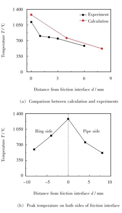
Fig.6 Peak temperature at different positions
3.2 Therm al cycle
Fig.7 shows the thermal cycle at different positions on both sides of the friction interface.The temperature on the friction interface straightly rises to a peak temperature in initial friction stage and keeps constant in the stable friction stage.The highest temperature on the friction interface reaches up to 1 200℃,is lower than themelting pointof1 350℃,which indicates that thematerial in the whole process does notmelt.
The temperature of positions away from friction interface is much lower than that of the friction interface,which indicates that the temperature gradient around the friction interface is very large.Fig.7 also shows that the temperature in the ring is higher than that in the pipe.

Fig.7 Continuous drive radial friction w eldingthermal cycle at different positions
3.3 Effect of welding parameters on thermal process
Fig.8 shows the influence of welding parameters on the thermal cycle of the friction interface,which indicates that the increase rate of temperature in the initial friction stage and the peak temperature with the increase of rotation speed temperature in the stable friction stage presents slightly increasing trend.The peak temperature varies in a small range(30℃)around 1 200℃,as shown in Fig.8a.Fig.8b shows the influence of friction pressure on the peak temperature of the friction interface at rotation speed of 750 rpm.The higher friction pressure is,the shorter time to achieve the stable friction process is,and there is a positive correlation between the increase rate of temperature and friction pressure in the initial friction stage,while the peak temperatures are hardly changed at different friction pressures.
3.4Heat generation power by friction
Fig.9 shows the influences of friction pressure and rotation speed on the heat generation power,which shows that all the variation trends for each curve are similar.

Fig.8 Effects of welding parameters on thermal cycle of friction interface
In the initial friction stage(0-3 s),the heat generation power firstly rises rapidly and reaches a peak value and then decreases gradually to a stable value.In the stable friction stage(3-6 s),the heat generation power keeps a relatively constant value.The friction coefficient reduces with the temperature increasing in the stable friction stage,so that the frictional resistance gradually decreases,which results in the decrease of the friction torque,thereby the heat generation power keeps stable when all the factors reach a dynamic balance.In the upsetting stage(6-6.2 s),the heat generation power rapidly decreases to 0,and the energy dissipation rapidly rises,which ismainly caused by that a lot of plastic metal at high temperature are squeezed out under the instantaneous upsetting pressure.
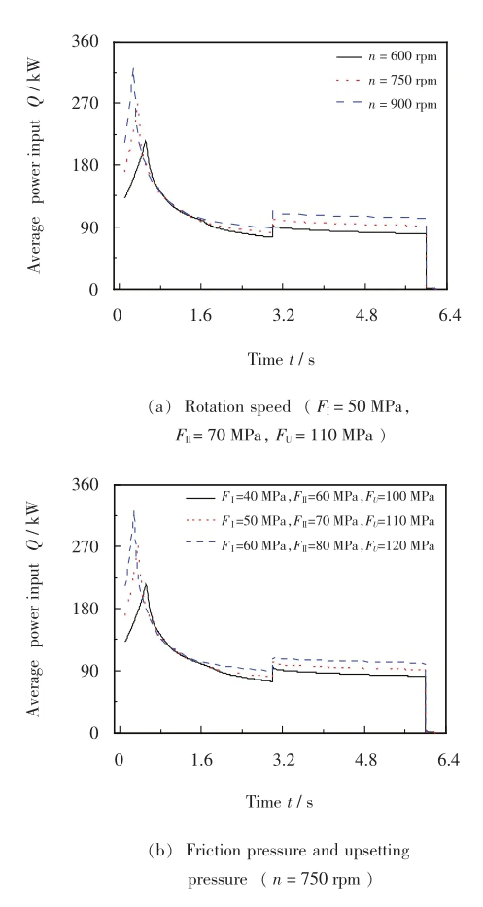
Fig.9 Effects of welding parameters on heat generation pow er
With the increase of friction pressure and rotation speed,the time to reach the peak heat generation power is less and the peak heat power is higher,but the heat power in the stable friction stage varies little.
4 Conclusions
(1)The temperature field in radial friction welding depends on welding parameters such as friction pressure,rotation speed,and friction time.The peak temperature onfriction interface during the process can reach up to 1 200℃,which is slightly higher than that tested by semi-natural thermocouple.
(2)The heat generation power increases rapidly to a peak level in the beginning and then decreases gradually to a relatively stable value in the stable friction stage.The welding parameters have some influences on the peak heat power value,but few influences on the stable heat power value.
References
[1] Nicholas E D,Lilly R H.Radial friction welding.Proceedings of Conference on Advances inWelding Processes,Harrogate,U.K.,1978:48.
[2] Nicholas E D.Radial friction welding.Welding Journal,1983,62(7):17s-29s.
[3] Deng AM.Research of the numericalsimulation and technology of radial friction welding of copper and alloy steel.Xi' an:Xi'an Jiaotong University,2002.(in Chinese)
[4] Hu J,Chen P.Analysis of clip-model of frictional welding with 3D finite elements.ElectricWelding Machine,2006,36 (2):52-55.(in Chinese)
[5] Wang G J,Lin ZM,Kang D D.Investigation on heat input numerical models of radial friction welding.Hot Working Technology,2010,39(11):158-159.(in Chinese)
[6] Zhang Y,Qin G L,Zhang C B,et al.Loading pressure numerical analysis on radial friction lap welding joint of steel pipe.Transactions of the China Welding Institution,2012,33(6):35-38.(in Chinese)
[7] Yan M G,Liu D P,Shi Ch X,et al.China aeronauticalmaterials handbook,Volume I.Beijing:Standards Press of China,1988.(in Chinese)
[8] Kautz D.ASM handbook(Vol.6).Ohio:ASM International,1993:150-155.
杂志排行
China Welding的其它文章
- Stress-strain characteristics of linear friction welding of TC11 and TC17 alloys*
- Effects of C/B4C ratio on Microstructure and property of Fe-based alloy coatings reinforced w ith in situ synthesized TiB2-TiC*
- Effects of Bi and rare earth metal on theMicrostructure and properties of Zn-based high-tem perature solder*
- Numerical analysis of keyhole establishment time in keyhole p lasma arc welding*
- Effect of pulse frequency on hardness characteristics of Al-Cu alloy HPVP-GTAW joints*
- Automatic defect detection in ultrasonic TOFD D-scan data using image processing m ethods*