Yaw error self-observation algorithm for pedestrian navigation via foot-mounted inertial navigation system
2015-06-15ZHANGXinxiZHANGRongGUOMeifengMILunaSONGMingliangZHANGYongjian
ZHANG Xin-xi, ZHANG Rong, GUO Mei-feng, MI Lu-na, SONG Ming-liang, ZHANG Yong-jian
(1. Department of Precision Instrument, Tsinghua University, Beijing 100084, China; 2. Department of Control Engineering, Academy of Armored Force Engineering, Beijing 100072, China)
Yaw error self-observation algorithm for pedestrian navigation via foot-mounted inertial navigation system
ZHANG Xin-xi1,2, ZHANG Rong1, GUO Mei-feng1, MI Lu-na1, SONG Ming-liang1, ZHANG Yong-jian1
(1. Department of Precision Instrument, Tsinghua University, Beijing 100084, China; 2. Department of Control Engineering, Academy of Armored Force Engineering, Beijing 100072, China)
The foot-mounted inertial navigation system (INS) based on low cost MEMS inertial sensors and zero velocity update (ZUPT) algorithm are widely used in pedestrian navigation. Due to the large drift of the MEMS inertial sensors, the observability of yaw angle is weak, and the yaw error of INS cannot be effectively restrained by ZUPT and becomes the main error source in pedestrian navigation. Based on the fact that most of the walking trajectories are close to a straight line, especially when walking in structural indoor corridors, a yaw error self-observation (YESO) algorithm is proposed to reduce the yaw error in straight walking. When the walking state is approximately a straight line, the heading angle calculated by the walking trajectory can be considered to be constant, and the changed value caused by various errors can be skillfully considered as the observations of yaw error in foot-mounted INS. The YESO algorithm can be used to estimate the yaw error to calibrate the yaw by using Kalman filter. A walking experiment up to 350 m in a building corridor verifies the effectiveness of YESO algorithm. The experiment results show that, when using ZUPT and ZUPT+YESO respectively, the error of heading angle is decreased to -2° from -29°, and the position error of south to north is decreased to -5.2 m from -35.5 m. The YESO algorithm only uses existing information without adding other sensors. It has practical values in engineering applications, and can also be easily applied in other fields like vehicle navigation.
pedestrian navigation; foot-mounted inertial navigation system; zero velocity update; yaw error self-observation; Kalman filter
The strap-down inertial navigation system (SINS) composed of a foot-mounted inertial measurement unit (IMU) is usually used in pedestrian navigation except the method of pedestrian dead reckoning (PDR)[1-4]. When the stance on the floor is detected, the zero velocity update (ZUPT) can be used, and the velocity error, position error and horizontal attitude error can be decreased. However, as the weak observability, the yaw error cannot be calibrated by ZUPT. Simultaneously the magnetometers and GNSS are not available in indoor, the yaw error cannot be restrained by the sensors above. For foot-mounted INS, the yaw error can be caused by gyroscope drifts, ZUPT error. In addition, the nonlinearity and the acceleration effect of gyroscope can lead to the equivalent errors[5-7]. Magnetometers can provide absolute yaw angle to limit the yaw error outside building where magnetic interference can be ignored. However, in indoor circumstance, magnetometers cannot be used because of interference. The unbounded yaw error becomes the main source of navigation error[8-10].
Several works have studied the method to restrain the yaw error without extra sensors. Ref [11] proposes the dominant direction based on the fact that in most buildings the direction of corridor is fixed. The dominant direction known in advance can be used to correct the yaw error. Ref [6] proposes algorithm named Heuristic Drift Reduction (HDR) based on PDR, which assumes that the output of vertical gyroscope is bias and need to be corrected in most cases. For HDR algorithm, a specially designed filter is needed to filter the output of gyroscope. After that, a binary integral controller can be used to reduce the yaw drift. The author also proposes an algorithm named Heuristic Drift Elimination (HDE), which is based on HDR algorithm and supposes the turning angles in most buildings to be 90° or other constant to eliminate the yaw error[12]. Ref [13] adopts two ultrasonic range sensors to identify that the walking is within the corridors and then the heading angle is strictly restrained. Other methods about yaw constrain include particle filtering based on building structures and human behavior in Ref [14-16]. Due to huge amount of calculation, the algorithm based on particle filter is hard to do real-time computing in pedestrian navigation.
The algorithm proposed in this paper is mainly based on the fact that pedestrians’ walking in indoor is along a straight line when there is no turn. As the calibration information is totally from the foot-mounted INS itself, the algorithm is called yaw error self-observation (YESO). The YESO algorithm consists of three parts. The first part is the calculation of initial heading angle, which can be calculated by the trajectory of the first few steps and remains until the turning motion after which the initial heading angle needs to be recalculated. The second part is the calculation of observations of yaw error. The difference between heading angle calculated in every step and the initial heading angle can be used as the observations of yaw error for foot-mounted INS. The third part is the detection of walking state and the estimation of navigation errors. Firstly, when the walking state is detected to be stance, ZUPT will be used, and the errors of horizontal attitude, velocity and position will be calibrated. During the time of stance, when the walking state is detected to be in a straight line, YESO algorithm will be applied besides ZUPT, yaw error will be estimated by Kalman filter and fed back to calibrate the yaw angle.
Fig.1 shows the structure diagram of YESO algorithm. Of course, the method in Ref [12] can be used to eliminate the error of yaw caused by turning. Compared with the method to correct gyroscope output in Ref [6], yaw error is estimated directly and fed back without complex filters designed for gyroscope in this paper. The structure of algorithm is more concise and practical.

Fig.1 Structure of YESO algorithm
1 Foot-mounted INS and ZUPT
1.1 Foot-mounted INS
For low-cost MEMS-based IMU, without external auxiliary sensors, the calculation error of INS grows rapidly, so it is unable to meet the needs of pedestrian navigation. By placing the IMU on foot, to constitute a foot-mounted strap-down inertial navigation system (SINS), we can take advantage of the feature that the INS velocity is zero when the foot landing to calibrate the INS. Foot-mounted INS can effectively reduce the accumulation of errors, and has achieved good results in practical applications[1,17]. Considering the IMU used in experiment is a tactical grade system whose precision is relatively high, so we use the standard algorithm of SINS in this paper.
1.2 ZUPT algorithm
1.2.1 Stance detection
In the foot-mounted INS, the stance detection is the basis of ZUPT. Most literatures are based on gyros’ and accelerators’ outputs[18], some papers rely on pressure sensors[19-20]or RF motion sensors[21]. In this paper we use the classical detection algorithm which uses the outputs of gyros and accelerators to detect the stance without any extra sensors.
The foot can be regarded as static when it touches the ground while walking. The IMU’s outputs aren’t zero because of the sway of the foot. However, the amplitudes decrease substantially. According to this character, the stance detection can be determined as follows. The 2-norm of the original output of gyros ω is calculated to detect stance, which is denoted as normω, while a threshold is set as thu_normω. When normωis less than thu_normω, the stance state can be detected, as shown in (1). In order to avoid some incorrect judgments while kicking, the mean square deviation (RMS)σnorm_ωof normωcan be calculated to detect stance too, while a threshold is set as thu_σnorm_ω, as shown in (3). As for accelerometers, the 2-norm of the original output of accelerometers a can be calculated to detect stance too, which is close to the gravity acceleration g0in the stance state. So the detection equation changes a little, as shown in (2) and (4).

Where ωx,ωy,ωzare the original outputs of gyros in carrier frame; ax,ay,azare the original outputs of accelerometers in carrier frame; n is the width of moving mean square estimator.
In order to increase the reliability of the stance detection, some conditions mentioned above (1)-(4) can be used together. In this paper, equation (1)-(3) are used together to detect the stance state. As shown in (5), stance_dindicates the state, 0 for stance and 1 for moving.

1.2.2 ZUPT implementation
ZUPT algorithm is widely applied to the error calibration of INS for vehicle. ZUPT algorithm utilizes the feature that the velocity is zero during carrier parking. For foot-mounted INS, the ZUPT algorithm is suitable. When the foot is on the ground, the velocity of foot-mounted INS is approximately zero, which can be used as the virtual observation. ZUPT algorithm uses the difference between the output of foot-mounted INS and a virtual velocity as the observations of velocity error in navigation frame. The observation equation of velocity error in navigation frame is shown in (6). Through the Kalman filter, the attitude error except yaw error, the velocity error and position error can be estimated, and the system error of foot-mounted INS can be calibrated[1-2,22].

2 Yaw Error Self-observation Algorithm
2.1 Heading angle for pedestrian
In the foot-mounted INS, the IMU is mounted on the foot directly. While walking, the foot’s motion is very complex, the tiptoe’s orientation swings left and right. The yaw angle of foot-mounted INS changes rapidly. As a matter of fact, the yaw angle of INS and the pedestrian’s heading angle are not the same angle, as shown in Fig.2. No matter how the foot or ankle moves while walking, especially walking along a straight line, the heading angle obtained from the walking trajectory changes slightly. Compared with the yaw angle of the foot-mounted INS, the heading angle characterizes the walking direction more precisely.

Fig.2 Yaw angle and heading angle
In the navigation frame, the east and north projection of each step are denoted asδSEand δSN. Then the pedestrian walking heading anglepψ can be defined as follows[11].

In the foot-mounted INS, the foot’s velocity is close to zero when walking state is stance. The point,) stands for the position at step epoch k when the foot touches to the ground, and the point,)is the position at previous step epoch k-1. Then δSEand δSNcan be calculated by equation (8). The heading angle of pedestrian walking ψpis calculated only once in a step.

The several steps at the beginning of pedestrian navigation have less heading errors because of the less accumulation of INS error. The walking trajectory have high reliability, the initial heading angle ψp_initcan be calculated by the walking trajectory. Because of the randomness of a person’s gait, the initial heading angle should be filtered even walking along a straight line. In this paper, a moving average filter is used. The basic equation is shown in (9). After each turning, the heading angle should be recalculated using the moving average filter.

2.2 Observations of yaw error
During the pedestrian navigation, the yaw angle ψINSof the foot-mounted INS is not the same angle with the walking heading angleψp. There is a difference angleΔψ between them. At the beginning of pedestrian navigation, the relationship of ψINSand ψpcan be expressed as follows:

For the same person on the same road, Δψchanges a little. The walking heading angle of each step denoted as pψ′ can be obtained in real-time calculation, as in (11). The real-time yaw angle of foot-mounted INS is denoted as ψI′NS, which satisfies the follow equation.

Minus equation (11) using (10), getting equation (12),

As shown in (12), the actual measurement error of yaw (δψ) can be obtained using the initial heading angle to minus the real-time heading angle. Then δψ can be used as the observations of yaw error in Kalman filter, and the yaw error can be estimated and used to correct the yaw.
2.3 Turning detection
In the general case, when walking along a straight or almost a straight line, the heading angle and the yaw angle both change slightly in adjacent two steps. However, they will increase significantly when turning a corner especially in indoor corridors, the increment of the heading angle or the yaw angle in adjacent two steps can be used to detect a turning state. In some circumstances, the foot’s state is so sophisticated that the yaw angle ψI′NSof foot-mounted INS and walking heading angle ψp′ vary significantly. It is not quite reliable to detect turning state only using one condition, and two conditions should be combined. The turning flag turndcan be determined by equation (13), 1 for turning a corner and others for walking along a straight. When walking along a straight, the value of turndis a coefficient which will be used in Kalman filter in the next section.

2.4 YESO algorithm implementation
2.4.1 Error state equation and observation equation
For foot-mounted INS, the transition model of navigation state vectors is a nonlinear function of the state vectors, therefore, the general Kalman filter cannot be used. However, the transition model of error state vectors can be considered as a linear function of the error state vectors[18]. Therefore, in this paper, the error state vectors and the general Kalman filter are used; the classical error state equation is used too[23]. The 12-element error state vector is:

Where δφn=[δθδγδψ]is the vector of attitude errors (roll, pitch and yaw); δvn=[δVEδVNδVU]is the vector of errors (east velocity, north velocity and up velocity) in navigation frame; δpn=[δLδλδh]is the vector of latitude error, longitude error and height error; εn=[εEεNεU]is the gyro bias (east gyro bias, north gyro bias and up gyro bias) in navigation frame.
The error state equation and error observation equation after the discretization are shown in (15) and (16):

Where Φk,k-1is the state transition matrix; Γk-1and Wkare respectively the noise intensity matrix and noise matrix, which satisfy the equation (17); H is the observation matrix; V is the observation noise matrix, which satisfies the following equation (18):

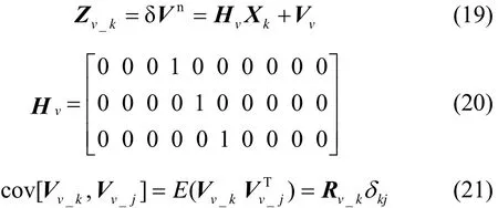
In this paper, when only using ZUPT, the error state of velocity can be observed directly. The observation equations are shown in (19), (20) and (21).
For YESO algorithm, the observation equations are shown in (22), (23) and (24). The observation noise covariance matrix Ryaw_kcan influence the estimation of yaw error. The value of Ryaw_kis smaller, the contribution of observation information is bigger. As in (13), even if the detection of turning state is walking along a straight, the real state may be a slow turning state, which can cause errors. The errors cannot be eliminated but in order to reduce the errors when walking a slow turning state, the Ryaw_kwill be multiplied by a coefficient, as in (13) and (25). The coefficient turndis bigger, the Ry′aw_kis bigger, and the negative impact caused by observation information is smaller.

The YESO algorithm cannot work independently in foot-mounted INS. The ZUPT algorithm is the base of YESO algorithm, so ZUPT and YESO algorithm work simultaneously. The united observation equations of ZUPT and YESO algorithm in kalman filter are shown in (26), (27) and (28).


2.4.2 Kalman filter and YESO algorithm flow
When estimating the system state of INS in this paper, we firstly estimate the error state vectors and then apply feedback to calibrate the system state of INS. The standard linear Kalman filter will be used for the estimation of INS errors[4]. For the first nine error vectors of [δφnδvnδpnεn], a closed loop Kalman filter will be used, namely the error vectors [δφnδvnδpn] will be set to zero after the feedback calibration; the gyro drift εnis not set to zero after the feedback calibration.
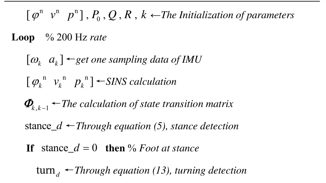
For pedestrian navigation, the entire state of motion can be divided into kick state and stance state. In the kick state, there are no observations for Kalman filter, Kalman filter runs time update merely. In stance state, ZUPT is always used to reduce the position error, velocity errors and attitude errors except the yaw error, equation (19), (20) and (21) are the observation equations of Kalman filter. When the flag of turning detection turndis not 1 during the stance state, the ZUPT and YESO algorithms are used simultaneously and yaw can be calibrated except the horizontal attitude, velocity and position. Equation (26)-(28) are the observation equations of Kalman filter when using ZUPT and YESO algorithms together. When the flag turndis 1, the ZUPT algorithm is used only. Because the heading angle calculated by the trajectory does not change during a step, the error feedback calibration of yaw will be performed once during a step. The pseudo code of the algorithm based on foot-mounted INS is shown in Algorithm 1.
Algorithm 1 ZUPT and YESO algorithm based on foot-mounted INS

If turnd≠1 then ψpk←Through equation (7) calculating heading angle; δψk←Through equation (12) calculating the observations of yaw error If initial several steps or after turning then ψk←Through equation (9), recalculating heading angle p_init End End If turnd≠1 and k=0 then Zk←Through equation (26)-(28), performing ZUPT and YESO algorithm once in a stance [δφnδvnδpnεn]←Through Kalman filter estimatingxkelse Zk←Through equation (19)-(21), perform ZUPT only [δφnδvnδpnεn]←Through Kalman filter estimatingxkEnd [φ˜nv˜np˜n]←Feedback calibration using the error state kkk xk[1:9]=0; % Closed loop Kalman filter k=k+1; % the number of calculation in a stance else xk|k-1=Φk|k-1xk-1; P=ΦPΦT+ΓQΓT; % time update when moving; k|k-1k|k-1k-1k|k-1k-1k-1k -1 k=0;End End Loop
3 Experiment and Verification
3.1 Equipment and trajectory
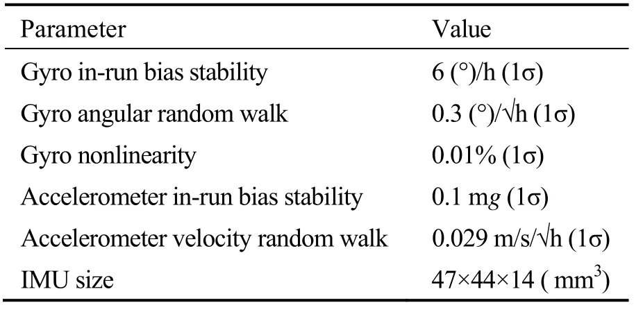
YESO algorithm is verified by using a tactical grade MEMS-based IMU ADI16488 made by Analog Devices Inc[24]. The IMU consists of a tri-axis gyroscope, a tri-axis accelerometer, a tri-axis magnetometer and a barometer. Some key specifications of ADI16488 are listed in Tab.1. The output rate of IMU is set 200 Hz. A real-time data acquisition circuit is designed to collect IMU data which is sent to a laptop using the serial port. The IMU data is saved in the field experiment and YESO algorithm is implemented in Matlab using the collected data.
As shown in Fig.3, the IMU and the data acquisition circuit are mounted on the top of the right shoe and the handheld laptop collects the IMU data in real-time. The carrier frame of foot-mounted INS is shown in Fig.3, which uses the right, front, up frame, while the navigation frame uses the east, north, up frame. As the toe point to the front direction of the INS in carrier frame, the yaw of the foot-mounted INS basically coincides with the toe direction.
The field experiment is conducted in the corridor of Department of Precision Instrument Building, Tsinghua University. As shown in Fig.4, the walking trajectory included six turnings and the total distance is about 350 m, with the terminal point overlapping the starting point. The walking direction along the trajectory is shown by the arrows.
Tab.1 Key specifications of ADI16488

Fig.3 Experiment equipment

Fig.4 Walking trajectory
3.2 Result and analysis
Since there is no absolute GPS position reference of the latitude and longitude in the corridor, the relative position coordinate in meters is used. The coordinate of the starting point is (0, 0) and the yaw angle solved by foot-mounted INS is defined within the range of [-180°,180°], in which -90° means the east,±180° the south,90° the west and 0° the north.
According to satellite image in Fig. 4, the corridor of the building is slightly away from the exact east-west direction. However, for ease of comparison, the initial yaw of the foot-mounted INS is set 90° (due west). To estimate the horizontal attitude angles, ZUPT is conducted during the 40 s of stance before starting to walk.
A field experiment is performed following the trajectory as shown in Fig.4, during which the IMU data are collected. Offline simulations using the proposed ZUPT+YESO algorithm and ZUPT only algorithm are implemented separately. The comparison and analysis of the results are described below.
3.2.1 Results of ZUPT algorithm

Fig.5 Comparison on pitch angles when using ZUPT or not
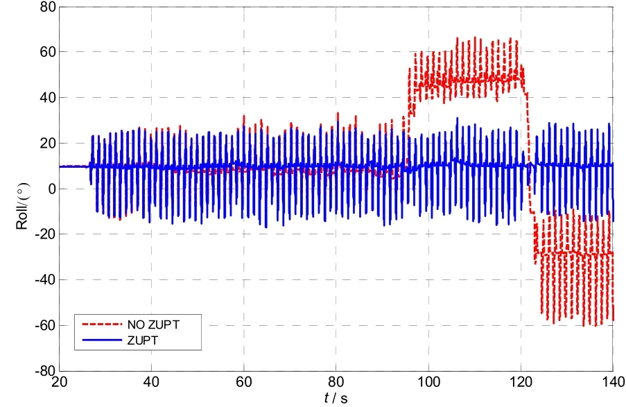
Fig.6 Comparison on roll angles when using ZUPT or not

Fig.7 Comparison on yaw angles when using ZUPT or not
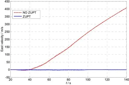
Fig.8 Comparison on east velocities when using ZUPT or not

Fig.9 Comparison on north velocities when using ZUPT or not

Fig.10 Comparison on up velocities when using ZUPT or not
At the normal state, the horizontal attitudes should change around a stable value because the horizontal attitudes are determined value when the foot is stance. The velocity should be zero when the foot is stance and should change around zero when walking. Considering the limitation of display scope, we take the calculation results of 20-140 s as the comparison value. As in Fig.5 and Fig.6, the pitch angle and roll angle diverge quickly when no ZUPT algorithm is used. As in Fig.7, the yawangle changes little no matter the ZUPT is used or not. As in Fig.8, Fig.9 and Fig.10, the velocity of east, north and up diverge quickly when no ZUPT algorithm is used. According to the result of ZUPT algorithm, we can summarize that the errors of attitude and the velocity can be restrained effectively except the yaw error.
3.2.2 YESO algorithm and comparison of two algorithms
In YESO algorithm, both the increment of INS yaw angle and the increment of walking heading angle are used to determine whether a turn maneuver is happening. Real-time increment of INS yaw angle (dashed line) and the increment of walking heading angle (solid line) are shown in Fig.11. Within the marked regions, corresponding to turn maneuvers, the increment of INS yaw angle and the increment of heading angle rise significantly at the same time, in the same direction and to the same magnitude. At the rest regions, corresponding to walking a straight line, the increment are all approximately zero mean white noise.
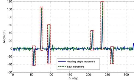
Fig.11 Heading angle increment and INS yaw angle increment
Simulations utilizing the ZUPT algorithm only and the proposed ZUPT+YESO algorithm are respectively executed, using the collected IMU data. The comparison of calculated trajectories, east distances, north distances, INS yaw angles and heading angles are shown in Fig.12 to Fig.16. Comparing the trajectories in Fig.12 with ideal trajectory in Fig.4, when using ZUPT only, calculated trajectory starts to deviate northward in the later period of trajectory A. The yaw error grows in trajectory B and eventually causes a maximum north distance error of -35.5 m in trajectory D. Meanwhile, when using ZUPT+YESO algorithm, calculated trajectory almost overlaps the ideal trajectory, with no obvious deviations in trajectory A and slight deviations in trajectory D, E and F. The maximum north distance deviation is decreased to -5.2 m.
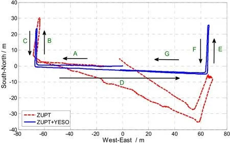
Fig.12 Calculated trajectories using ZUPT only and ZUPT+YESO
Fig.13 shows that the curve of calculated east distances using ZUPT only and ZUPT+YESO are close, which indicates that ZUPT effectively suppresses east distance error. However, as shown in Fig.14, using ZUPT only lead to obvious north distance error, which means yaw error is not well suppressed. After adding YESO algorithm, although the coordinate of finish point merely changes from (4.4 m,-2.5 m) to (-2.4 m, -2 m), the maximum north distance error decreases significantly from -35.5 m to -5.2 m.

Fig.13 Calculated east distances using ZUPT only and ZUPT+YESO
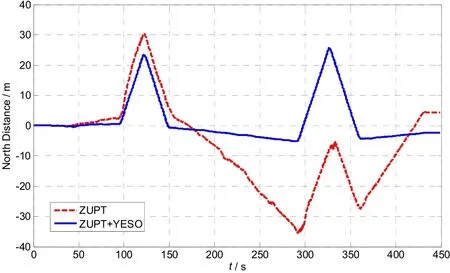
Fig.14 Calculated north distances using ZUPT only and ZUPT+YESO
Fig.15 shows the calculated INS yaws using ZUPT only and ZUPT+YESO. Comparing Fig.15 with ideal trajectory in Fig.4, when using ZUPT only, INS yaw error starts togrow in trajectory A. The difference between INS yaw angles calculated by the two algorithms grows to 28° in trajectory F. The observation noise covariance matrix in Kalman Filter can be adjusted to reduce the estimation noise of yaw error caused by the uncertainty of pedestrian walking, so the curve of yaw looks smooth.

Fig.15 Calculated yaw using ZUPT only and ZUPT+YESO
Fig.16 shows calculated heading angles using ZUPT only and ZUPT+YESO. The ideal heading angle values of the start point and the final point are 90°. When using ZUPT only, the error of walking heading angle cumulates to the final value -29°. When adding YESO algorithm the final error of heading angle decreases to -2°, also the error range of heading angle are significantly reduced.
For validating the effectiveness of YESO algorithm when using the lower precision sensors, an experiment is designed. The gyro itself in ADI16488 has a zero-bias about 100 (°)/h. We superimpose a bias (720 (°)/h, 5 mg) on the raw outputs of tri-gyros and tri-accelerometers respectively, so as to simulate the lower precision sensors. Calculation utilizing the ZUPT algorithm and the proposed ZUPT+YESO algorithm are respectively executed. As in fig.17, the experiment result shows that the position precision is significantly higher using ZUPT+YESO algorithm than using ZUPT algorithm only.

Fig.16 Calculated heading angle using ZUPT only and ZUPT+YESO
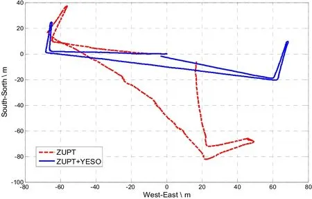
Fig.17 Calculated trajectories using ZUPT only and ZUPT+YESO after superposing a bias
The comparison of the two experiment results using ZUPT only and ZUPT+YESO are summarized in Tab.2. The experiment results show that adding YESO algorithm effectively suppresses the yaw error and significantly improves the position accuracy of pedestrian navigation.

Tab.2 Navigation errors of various algorithms
4 Conclusion
The algorithm proposed in this paper is effective in suppressing the position error caused by the yaw error. However, during turning maneuvers, gyro drifts cannot be restrained, and the yaw error is cumulative and cannot be eliminated. Therefore, the proposed algorithm can only reduce the errors of yaw angle and position rather than completely eliminate them.
In our implement, the thresholds of turning detection are set as a key criterion, which must be properly setthrough the real test. If the thresholds are set too large, a slowly turning will be easily mistaken as a straight line state. On the other hand, if the thresholds are set too small, a walking in straight line state may be determined as a turning, causing frequent changes between walking states.
A walking experiment up to 350 m has been conducted in a building corridor. The experiment result shows that the errors of heading angle and south to north position diminish significantly. The accuracy of pedestrian navigation is improved significantly by using YESO algorithm. The YESO algorithm, without extra sensors added, can conveniently be used with ZUPT algorithm together through Kalman filter. The calculation burden of YESO algorithm is much smaller than the particle filter, and can be used to the real-time computing. It is very suitable for pedestrian navigation or vehicle navigation especially in structural roads such as indoor corridors.
REFERENCES:
[1] Fourati H. Heterogeneous data fusion algorithm for pedestrian navigation via foot-mounted inertial measurement unit and complementary filter[J]. IEEE Transactions on Instrumentation and Measurement, 2014, 64(1): 221-229.
[2] Skog I, Nilsson J, Handel P. Evaluation of zero-velocity detectors for foot-mounted inertial navigation systems[C] //IEEE IPIN, 2010: 1-6.
[3] Zhang Hemin, Yuan Weizheng, Shen Qiang, et al. A handheld inertial pedestrian navigation system with accurate step modes and device poses recognition[J]. IEEE Sensors Journal, 2015, 15(3): 1421-1429.
[4] Kang W, Han Y. Smart PDR: Smartphone-based pedestrian dead reckoning for indoor localization[J]. IEEE Sensors Journal, 2015, 15(5): 2906-2916.
[5] Bancroft J B, Lachapelle G. Estimating MEMS gyroscope g-sensitivity errors in foot mounted navigation [C]//Ubiquitous Positioning, Indoor Navigation, and Location Based Service. Helsinki, 2012: 1-6.
[6] Borenstein J, Ojeda L, Kwanmuang S. Heuristic reduction of gyro drift for personnel tracking systems[J]. The Journal of Navigation, 2009, 62(1): 41-58.
[7] Fan C, Hu X, He X. Observability analysis of a MEMS INS/GPS integration system with gyroscope g-sensitivity errors[J]. Sensors, 2014, 14(9): 16003-16016.
[8] Yadav N, Bleakley C. Accurate orientation estimation using AHRS under conditions of magnetic distortion[J]. Sensors, 2014, 14(11): 20008-20024.
[9] Afzal M H, Renaudin V, Lachapelle G. Use of Earth’s magnetic field for mitigating gyroscope errors regardless of magnetic perturbation[J]. Sensors, 2011, 11(12): 11390-11414.
[10] Wahdan A, Georgy J, Noureldin A. Three-dimensional magnetometer calibration with small space coverage for pedestrians[J]. IEEE Sensors Journal, 2014, 15(1): 598-609.
[11] Abdulrahim K, Hide C, Moore T. Aiding low cost inertial navigation with building heading for pedestrian navigation[J]. J Navigation, 2011, 64: 219-233.
[12] Borenstein J, Ojeda L. Heuristic drift elimination for personnel tracking systems[J]. J Navigation, 2010, 63: 591-606.
[13] Girard G, Côté S, Zlatanova S, Barette Y. Indoor pedestrian navigation using foot-mounted IMU and portable ultrasound range sensors[J]. Sensors, 2011, 11(8): 7606-7624.
[14] Gu Y, Song Q, Li Y, Ma M. Foot-mounted pedestrian navigation based on particle filter with an adaptive weight updating strategy[J]. J Navigation, 2015, 68: 23-38.
[15] Robertson P, Angermann M, Krach B. Inertial systems based joint mapping and positioning for pedestrian navigation[C]//ION GNSS 2009. 2009: 2096-2107.
[16] Pinchin J, Hide C, Moore T. A particle filter approach to indoor navigation using a foot mounted inertial navigation system and heuristic heading information[C]//Indoor Positioning and Indoor Navigation. 2012: 1-10.
[17] Handel. P, Nilsson J, Skog I. Foot-mounted INS for everybody: An open-source embedded implementation [C]//IEEE/ION Position Location and Navigation Symposium. 2012: 140-145.
[18] Skog I, Nilsson J, Handel P. Evaluation of zero-velocity detectors for foot-mounted inertial navigation systems [C]//IEEE IPIN2010, 2010: 1-6.
[19] Bebek O, Suster M A, Rajgopal S, et al. Personal navigation via high-resolution gait-corrected inertial measurement units[J]. IEEE Transactions on Instrumentation and Measurement, 2010, 59(11): 3018-3027.
[20] Zelun Z, Poslad S. Improved use of foot force sensors and mobile phone GPS for mobility activity recognition [J]. IEEE Sensors Journal, 2014, 14(12): 4340-4347.
[21] Zhou C M, Downey J, Choi J, et al. A shoe-embedded RF sensor for motion detection[J]. IEEE Microw Wirel Co, 2011, 21(3): 169-171.
[22] Jimenez A R, Seco F, Prieto J C, Guevara J. Indoor pedestrian navigation using an INS/EKF framework for yaw drift reduction and a foot-mounted IMU[C]// Positioning Navigation and Communication. Dresden, 2010: 135-143.
[23] 郭美凤, 林思敏, 周斌, 等. MINS/GPS一体化紧组合导航系统[J]. 中国惯性技术学报, 2011, 19(2): 214-219. Guo Mei-feng, Lin Si-min, Zhou Bin, et al. MINS/GPS tightly-coupled integrated navigation system[J]. Journal of Chinese Inertial Technology, 2011, 19 (2): 214-219.
[24] ADI Inc. ADI16488 [EB/OL]. [2011-11-12]. http://www. analog.com/en/mems-sensors/mems-inertial-sensors/ adis16488/products/product.html.
[25] 钱伟行, 彭晨, 田恩刚, 等. 基于导航信息双向融合的行人/移动机器人协同导航方法[J]. 中国惯性技术学报, 2014, 22(1): 74-78. Qian Wei-xing, Peng Chen, Tian En-gang, et al. Pedestrian /mobile robat cooperative navigation method based on navigation information bidirectional fusion[J]. Journal of Chinese Inertial Technology, 2014, 22(1): 74-78.
足绑式行人导航偏航角误差自观测算法
张新喜1,2,张 嵘1,郭美凤1,宓璐娜1,宋明亮1,张永健1
(1. 清华大学 精密仪器系,北京 100084;2. 装甲兵工程学院 控制工程系,北京 100072)
基于低成本MEMS惯性传感器的足绑式惯性导航系统(INS)和零速修正(ZUPT)算法广泛应用于行人导航中。由于MEMS惯性传感器零漂误差较大,零速修正时偏航角误差的可观测性差,INS偏航角误差不能被有效约束,成为行人导航的主要误差源。行人徒步行走特别是在室内楼道等结构化道路上行走时,行走的轨迹大多情况下可认为是近似直线,基于这个事实,提出了一种减小偏航角误差的算法,称为偏航角误差自观测(YESO)算法。当判定行人以近似直线徒步行走时,由行走轨迹计算出的航向角可近似认为是一个常值,那么由于各种误差引起该航向角发生变化时,可以将该变化量作为足绑式INS偏航角误差的观测量,进一步可利用卡尔曼滤波器估计出偏航角误差,对足绑式INS的偏航角进行校准。在室内楼道进行了约350 m的现场实验,实验验证了YESO算法的有效性。实验结果表明,当分别采用ZUPT和ZUPT+YSEO算法进行导航解算时,航向角误差从-29°减小到-2°,南北向最大位置误差从-35.5 m减小到-5.2 m。YESO算法的实现仅依靠系统自身的信息,没有增加额外的传感器,算法具有很好的工程实用价值并能方便地推广应用于车辆导航等领域。
行人导航;足绑式惯性导航系统;零速修正;偏航角误差自观测;卡尔曼滤波
U666.1
A
1005-6734(2015)04-0457-10
2015-04-10;
2015-07-23
中国第二代卫星导航系统重大专项(GFZX0301010516);总装惯性技术预先研究项目(51309010301)
张新喜(1980—),男,博士研究生,从事微型自主定位导航研究。E-mail:thuxinxi@163.com
10.13695/j.cnki.12-1222/o3.2015.04.008
联 系 人:张嵘 (1969—),男,研究员,博士生导师。E-mail:rongzh@mail.tsinghua.edu.cn
