Theoretical and Numerical Research on CTOD for Ship Plate under Cyclic Loading Considering Accumulative Plastic Strain
2015-05-02DONGQinYANGPingDENGJunlinWANGDn
DONG Qin,YANG Ping,DENG Jun-lin,WANG Dn
(a.School of Transportation;b.Key Laboratory of High Performance Ship Technology of Ministry of Education,Wuhan University of Technology,Wuhan 430063,China)
Theoretical and Numerical Research on CTOD for Ship Plate under Cyclic Loading Considering Accumulative Plastic Strain
DONG Qina,YANG Pingb,DENG Jun-lina,WANG Dana
(a.School of Transportation;b.Key Laboratory of High Performance Ship Technology of Ministry of Education,Wuhan University of Technology,Wuhan 430063,China)
The Crack Tip Opening Displacement(CTOD)is one of the important parameters for studying the low-cycle fatigue of plate sustaining large scale yielding.The CTOD value can reflect the ability of material resistance to crack initiation and propagation,and it is an important parameter to evaluate material toughness as well as the main controlling parameter to analyze the crack propagation due to low-cycle fatigue damage.In this paper,based on the theory of elastic-plastic fracture mechanics,the cyclic J integration is explored as breakthrough point and accumulative plastic strain at crack tip as the significant parameter,an analytical model is presented to determine the CTOD for the central-through cracked plates subjected to cyclic axial in-plane loading.Also,the finite element analysis is conducted to investigate the influence of stress ratio and stress amplitude.The new accumulative plastic strain-based CTOD estimation formulations presented in this paper provides a new way for low-cycle fatigue analysis considering accumulative plastic damage for central-through cracked plates under high cyclic loadings.
central-through cracked plate;cyclic loading;accumulative plastic strain;
0 Introduction
Along with the increasing in ship dimensions and more use of high-strength steel in recent years,the stress and deformation of ship structures are so high and large,which result in prominent problem demanding prompt solution in the development of large-scale ships.For cracked plate of ship and marine structures,plastic strain would generate in the region near crack tip when the local stress reaches the yield strength.When a ship subjects to cyclic loading,plastic strain would accumulate in local region of the crack tip,and this accumulative incremental plastic strain would speed up the fracture failure of the structure when it accumulates to a certain degree along with the increasing of the cyclic loading.Crack tip opening displacement(CTOD)and J integration are the major parameters to describe crack propagation ofductile structural materials(Hutchinson,1982)[1].However,J integration is rarely used to assess the structure fracture under cyclic loading because it cannot be applied to unloading state.Therefore,studying and establishing assessment methods of CTOD based on accumulative plastic strain under cyclic loading are of great practical significance.
CTOD reflects the plastic deformation performance in the region near crack tip and the resistance of material fracture toughness at crack tip.It is a measurement of plastic deformation at crack tip,so it is widely used as a criterion of the fracture failure.Previously,CTOD calculation models based on stress intensity factor had been proposed for applying only to linear elastic state(Dugdale,1960;Cottrell,1975;Yaowu Shi,1998)[2-4].Dugdale(1960)model has been widely studied and used for establishing the corresponding relationship between external load and crack parameters.Jiang(2005)[5]analyzed CTOD of ship stiffened plate based on Dugdale model and found out the influence rule caused by external load,stiffness ratio and other factors.Finite element method(Potirniche et al,2003;Wu,2009;Chen,2011,2015)[6-9]is one of the efficient ways in studying elastic-plastic fracture problems,thus it is widely used in various kinds of fracture assessments.It is used to study CTOD and other relative parameters through calculation of crack tip stress-field and displacement-field.Potirniche et al (2003)[6]calculated the size of crack tip plastic zone and CTOD of the steady microscopic structural small crack,and high precision CTOD is obtained through bringing two-dimensional small strain constitution relation of the single crystal plasticity theory into finite element software ANSYS.Wu(2009)[7]proposed an effective method to estimate fracture toughness of the test specimen based on the numerical results of CTOD.In their study,elastic-plastic finite element method is used to calculate the CTOD,taking tensile specimen with axial notch as research object.Chen(2011,2015)[8-9]has carried out numerical analysis of CTOD based on the crack maximum opening displacement(CMOD),and simplified the finite element calculation model by eliminating the effects of external load,model dimensions,material properties and crack length.Besides,some researchers have studied CTOD based on the local strain of the crack tip and proposed the CTOD calculation model that can only be applied to low strain and static loading(Schwalbe,1994;Linkens et al,2000;Jayadevan et al,2004)[10-12].Hiroshi (2007)[13]presented a new method to assess local stress based on the relationship between local stress and linear elastic fracture mechanics.He discussed corresponding relationship between local strain and CTOD,and realized the idea to determine CTOD based on local strain by twodimensional finite element method.There are a lot of discussions about using these calculation models for cracked structures under complex load.At present,many researchers have studied CTOD under complex load and obtained their corresponding conclusions.Alike putting forward CTOD calculation models(Bjerke et al,2011;Yi et al,2014)[14-15],Ostby(2005)[16]calculated large plastic strain of cracked pipeline structure and proposed a simple CTOD evaluation method based on the plastic strain.Zhang(2014)[17]discussed the CTOD evaluation model for marine pipeline structure under large plastic strain,considering the influence of crack size,material hardening exponent and external load.
Among the above mentioned analyses,the studies on CTOD are either confined to linear elastic state or only about finite element analysis of plastic strain under static load.There is few fracture assessment about cracked plate under LCF load.Taking central-through cracked plate as the study object,the paper establishes a CTOD calculation model based on accumulative plastic strain at crack tip,meanwhile,the influence of stress ratio and stress amplitude are analyzed through numerical simulation.The analysis provides a feasible way for fracture failure assessment for ship and marine structural component under actual cyclic loading.
1 Theoretical analysis
According to Shih[18],a simple relationship exists between the J-integration and the crack tip opening displacement for central-through cracked plate subject to uniaxial loading:

where σyis the yield stress and dnrelies on the hardening behavior of the material.For powerlaw hardening materials the crack-tip stress-strain fields are the Hutchinson,Rice and Rosengren(HRR)[19-20]singular fields.In this case,dnis a function of the Ramberg-Osgood hardening exponent n and was tabulated by Shih[21]for both plane strain and plane stress.The tabulated values for plane stress given by Shih[21]can be fitted with a third order polynomial function:

If cyclic loading is considered,the cyclic J-integration△J has a solid mathematical foundation if the material shows Masing behavior.All properties in Eq.(1)have to be replaced by their cyclic counterparts.Following Kumar et al[22]and Heitmann et al[23],△J can be approximated by the sum of an elastic(small scale yielding)and a plastic contribution.For I crack with crack length a in a flat specimen under plane stress,one obtains:

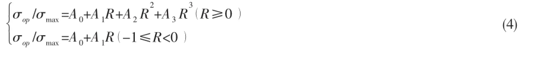
where n′is the cyclic hardening exponent,σcyis the cyclic yield stress and E is Young’s modulus.△σ and△εplare the stress and plastic strain range,respectively.Crack closure is taken into account by the use of the effective stress range△σeff=σmax-σopin the elastic part of△J.σmaxand σopare the maximum and crack opening stress,respectively.All quantities in Eq.(3)can be determined from stress-strain hysteresis loops except σop,which can either be estimated with empirical formulas or taken from numerical calculations.Here,the crack opening stress equation by Newman[24]is used,which predicts decreasing crack opening stresses with increasing maximum stresses,as is observed under LCF conditions.
The equation between plastic strain and accumulative plastic strain in Chaboche[25]can be differentiated as:

where△pn+1is the equivalent plastic strain increment in the n+1 cycle,which can be obtained by Newton-Raphson iteration.So the accumulative plastic strain increment△εn+1after n+1 cycles can be calculated.Plastic strain increment in each cycle can also be derived by updating the corresponding parameters.The relationship between plastic stress and strain of the central cracked plate at crack tip in n+1 cycle can be expressed as Ramberg-Osgood[26-27]:
Substituting Eq.(6)into Newton-Raphson[25]iteration formula,thus plastic strain increment△pn+1after n+1 cycles can be calculated,and accumulative plastic strain increment△εn+1after n+1 cycles can be obtained by Eq.(5).
The central-through cracked plate in the paper only subjects to uniaxial cyclic loading, therefore the relationship between accumulative plastic strain increment after n+1 cycles and plastic strain increment in n+1 cycle can be expressed as:

According to Eq.(5)~Eq.(7),the accumulative plastic strain after n+1 cycles can be written as:

Therefore,Eq.(8)is the expression for the value of the accumulative increment plastic strainaround crack tip of central-through cracked plate after n+1 cycles.
According to Eq.(3)and Eq.(8),an analytical model is presented in this paper to determine the CTOD allowing for the influence of accumulative plastic strain for the centralthrough cracked plates subjected to cyclic axial in-plane loading.
2 Finite element analysis and discussion
A central-through cracked plate(length=2L,width=2W,crack length=2a)is considered to study the stress and strain behavior near the crack tip under cyclic loading.The finite element software ANSYS is used to conduct the parametric modeling and finite element analysis for ship plate with central-through crack.Plane 82 with 8 node is adopted as the element type and the material model adopted is essentially the constitutive equations by Chaboche,where both isotropic and kinematic hardening variables are considered during the cyclic response. The geometry model and finite element model of ship plate with central-through crack is shown in Fig.1.Singular element is used to deal with crack tip and refined mesh is adopted in crack tip region.Stainless steel 304 is selected in the finite element model and Tab.1 shows the material parameters.
2.1 Near-tip stress-strain field under cyclic loading
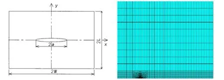
Fig.1 Geometry model and finite element model of ship plate with central through crack

Tab.1 Material parameters of 304 stainless steel
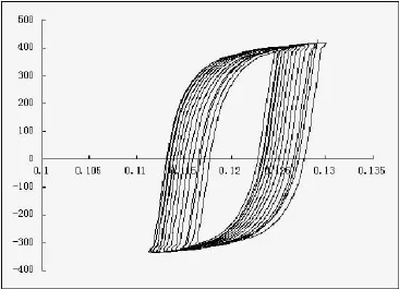
Fig.2 The stress-strain curve near the crack tip of Chaboche cyclic plastic model
Finite element computations are carried out over 100 cycles at selected load ratios at maximum external load of 240 MPa.The hoop stress-strain loop atcrack tip for central-through cracked plate is shown in Fig.2.The stress-strain loop exhibits a progressive shift in the direction of increasing tensile strain,which means the plastic strain accumulates obviously at crack tip under constant amplitude cyclic loading.
2.2 The relationship between accumulative plastic strain and cyclic number
According to the calculation of the finite element model in Fig.1,the relations of accumulative plastic strain to stress ratio and stress amplitude are shown in Figs.3-4.The size of the central-through cracked plate is L=150 mm,W=130 mm,a=10 mm,change stress ratio and stress amplitude R=0.1,R=0.2,R=0.3,σa=240 MPa,σa=260 MPa,σa=280 MPa,the results are obtained through a series of numerical simulation.
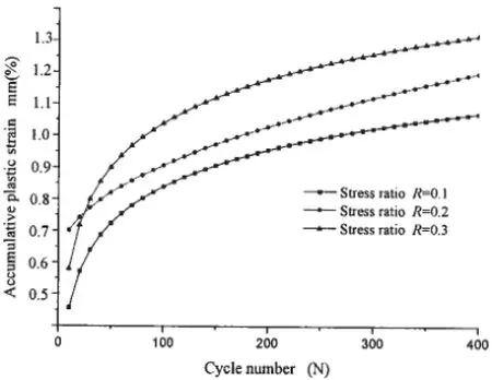
Fig.3 The curve of accumulative plastic strain vs cyclic number under different stress ratio
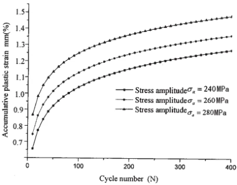
Fig.4 The curve of accumulative plastic strain vs cyclic number under different stress amplitude
These results seem to suggest that whilst the stress/strain range near the crack tip remains fairly constant during the cyclic loading and scales with the external load range,the accumulative plastic strain increases and is associated with stress ratio and stress amplitude.The continuous increase of the accumulative plastic strain may eventually lead to the material separation near the crack tip hence crack propagation.The results suggest that,in the near-tip stress-strain field,the accumulative plastic strain increases with the increase of stress ratio and stress amplitude,admittedly these results are based on a stationary crack,which reveals that the stress ratio and stress amplitude affect accumulative plastic strain significantly under cyclic loading.
2.3 The relationship between Crack Tip Opening Displacement(CTOD)and cyclic number
According to the calculation of the finite element model in Fig.1,the relations of crack tip opening displacement to stress ratio and stress amplitude are shown in Figs.5-6.The size of the central-through cracked plate is L=150 mm,W=130 mm,a=10 mm,change stress ratio and stress amplitude R=0.1,R=0.2,R=0.3,σa=240 MPa,σa=260 MPa,σa=280 MPa,the results are obtained through a series of numerical simulation.
Figs.5-6 show that for constant stress ratio and stress amplitude,the crack tip opening displacement increases with the cyclic number under constant cyclic loading.It can be seen that in the near-tip stress-strain field,the CTOD increases with the increase of stress ratio andstress amplitude,which reveals that the stress ratio and stress amplitude affect CTOD significantly under cyclic loading.
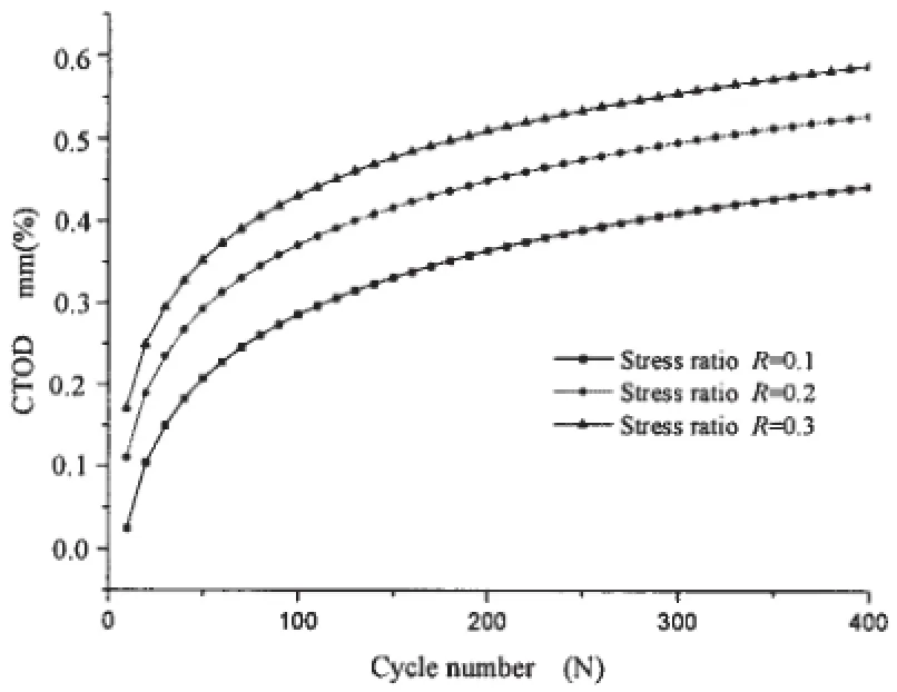
Fig.5 The curve of CTOD vs cyclic number under different stress ratio
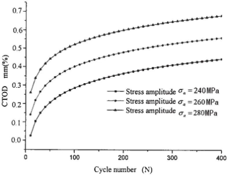
Fig.6 The curve of CTOD vs cyclic number under different stress amplitude
3 The relationship between CTOD and accumulative plastic strain at crack tip under cyclic loading
According to Eq.(3),an analytical model is presented in this paper to determine the CTOD based on accumulative plastic strain for the central-through cracked plates subjected to cyclic axial in-plane loading.To keep the integrity of this work,some influence factors are taken into account.For the finite element model shown in Fig.1,the relation of△CTOD and△εpof the central-through cracked plate under cyclic loading allowing for the influence of stress ratio and stress amplitude have been calculated and compared with analytical results.
3.1 The effect of stress ratio
To investigate the influence of stress ratio on the functional relationship between△CTOD and△εp,keep stress amplitude σa=240 MPa unchanged and different stress ratio R=0.1,R=0.2,R=0.3.The△CTOD and△εpcan be calculated with the same material parameters shown in Tab.1.To compare with analytical results Eq.(3),the results are shown in Fig.7.
It is seen from Fig.7 that,the crack tip opening displacement of central-through cracked plate monotonically increases with accumulative plastic strain for the increasing of stress ratio.It is obvious that the stress ratio apparently influence the relationship between CTOD and accumulative plastic strain,i.e.,the CTOD rapidly increases with stress ratio at a constant stress amplitude.It can be found from Fig.7,the finite element results are consistent with prediction results,and show smaller dispersion.It indicates the prediction model can well reflect the behavior of CTOD under cyclic loading and shows certain feasibility and good precision.

Fig.7 The curve of CTOD vs accumulative plastic strain under different stress ratio
3.2 The effect of stress amplitude
To investigate the influence of stress amplitude on the functional relationship between△CTOD and△εp,keep stress ratio R=0.1 unchanged and different stress amplitude σa=240 MPa,σa=260 MPa,σa=280 MPa.The△CTOD and△εpcan be calculated with the same material parameters shown in Tab.1.To compare with analytical results Eq.(3),the results are shown in Fig.8.
It is seen from Fig.8 that,the crack tip opening displacement of central-through cracked plate monotonically increases with accumulative plastic strain for the increasing of stress amplitude and the effect of stress amplitude is more significant than that of stress ratio.It is obvious that the stress amplitude apparently influences the relationship between CTOD and accumulative plastic strain,i.e.,the CTOD rapidly increases with stress amplitude at a constant stress ratio.It can be found from Fig.8,the finite element results are consistent with prediction results,and show smaller dispersion.It indicates the prediction model can well reflect the behavior of CTOD under cyclic loading and shows certain feasibility and good precision.
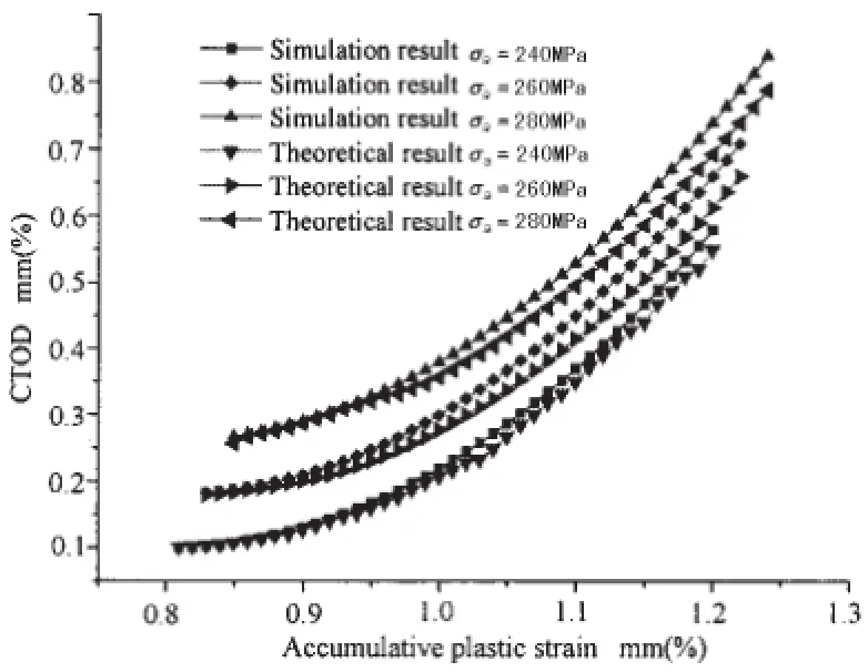
Fig.8 The curve of CTOD vs accumulative plastic strain under different stress amplitude
4 Conclusions
Based on the theory of elastic-plastic fracture mechanics,we explore the cyclic J integration as breakthrough point and accumulative plastic strain at crack tip as the significant parameter,an analytical model is presented in this paper to determine the CTOD for the centralthrough cracked plates subjected to cyclic axial in-plane loading.Also in the present work,the finite element analysis is conducted to investigate the influence of stress ratio and stress amplitude.The conclusions can be drawn as follows:
(1)The results suggest that the accumulative plastic strain increases during the cyclic loading and is associated with stress ratio and stress amplitude.
(2)The study reveals that stress ratio and stress amplitude have obvious influence on the relationship of CTOD vs.accumulative plastic strain.The finite element results are consistent with prediction results and show smaller dispersion.It indicates the prediction model can well reflect the behavior of CTOD under cyclic loading and shows certain feasibility and good precision.
[1]Hutchinson J W.Fundamentals of the phenomenological theory of nonlinear fracture mechanics[J].J Appl.Mech.,1982, 49:103-197.
[2]Dugdale D S.Yielding of steel sheets containing slits[J].J Meeh.Phys.Solids,1960,8:100-108.
[3]Cottrell A H.Mechanisms of fracture,the 1963 Tewksbury lecture[R].Tewksbury 146 SymPo.On Fracture,1963:1-27.
[4]Yaowu S,Siying S,Hidekazu M,et al.Finite element analysis on relationships between the J-integral and CTOD for stationary cracks in welded tensile specimens[J].Pres.Ves.PIP.,1998,75:197-202.
[5]Jiang Cuixiang.Research on fracture and crack arrest in ship structures[D].Wuhan:Ph.D.Dissertation of Huazhong University of Science and Technology,2005.
[6]Potirniehe G P,Daniewiez S R.Analysis of crack tip plasticity for microstructuralIy small cracks using crystal plasticity theory[J].Eng.Fraet.Meeh.,2003,70:1623-1643.
[7]Wu F W,Ibrahim R N,Das R,et al.Fracture toughness for CNT specimens from numerieally obtained critical CTOD values[J].Theor.Appl.Fract.Meeh.,2009,52:50-54.
[8]Chen Jingjie.Strength analysis method research of cracked ship structure[D].Dalian:Dalian University of Technology,2011.
[9]Chen Jingjie,Huang Yi.A study on evaluation method of crack tip reverse plastic zone size for the center cracked steel plate model under tension-compression cyclic loading[J].Engineering Fracture Mechanics,2015,133:138-151.
[10]Schwalbe K H.The crack tip opening displacement and J integral under strain control and fully plastic conditions estimated by the engineering treatment model for planes tress tension[J].In:Fracture Mechanics:Twenty-fourth vol.ASTM,Philadelphia,1994:636-651.
[11]Linkens D,Formby C L.Astrain-based approach to fracture assessment-example applications[C]//In:Proceedings of Fifth International Conference on Engineering Structural Integrity Assessment.Cambridge,EMAS,2000:45-52.
[12]Jayadevan K R,Østby E,Thaulow C.Strain-based fracture mechanics analysis of pipelines[C]//In:Proceedings of International Conference on Advances in Structural Integrity.Bangalore,2004.
[13]Shimanuki Hiroshi,INOUE,Takehiro.Study on the CTOD estimation method of the crack in stress concentrated area[J]. Japan Welding Association Conference Proceedings,2007,25(l):230-237.(in Japanese)
[14]Bjerke S L,Scultori M.DNV’s strain-based fracture assessment approach for pipeline girth welds[C]//In:Proceedings of the International Offshore and Polar Engineering Conference,ISOPE,2011,21:690-697.
[15]Yi D K,Xiao Z M.One lastic-plastic fracture behavior of a bi-layered composite plate with a sub-interface crack under mixed mode loading[J].Compos.PartB:Eng.,2014,60:60-73.
[16]Østby E,Jayadevan K R,Thaulow C.Fracture response of pipelines subject to large plastic deformation under bending[J]. Int.J Press.VesselsPip,2005,82:201-215.
[17]Zhang Y M,Xiao Z M,et al.Strain-based CTOD estimation formulations for fracture assessment of offshore pipelines subjected to large plastic deformation[J].Ocean Engineering,2014,91:64-72.
[18]Shih C F.Relationship between the J-integral and the crack opening displacement for stationary and extending cracks[J]. Mech Phys Solids,1981,29(4):305-326.
[19]Hutchinson J W.Singular behavior at the end of a tensile crack in a hardening material[J].Mech Phys Solids,1968,16:13-31.
[20]Rice J R,Rosengren G F.Plane strain deformation near a crack tip in a power-law hardening material[J].Mech Phys Solids,1968,16:1-12.
[21]Shih C F.Tables of Hutchinson-Rice-Rosengren singular field quantities[R].Tech.rep.Brown University Report MRL E-147,1983.
[22]Kumar V,German M D,Shih C F.An engineering approach for elastic-plastic fracture analysis[R].Tech.rep.Report NP-1931 on Project 1237-1 for Electric Power Research Institute,Palo Alto,California,1983.
[23]Heitmann H H,Vehoff H,Neumann P.Advances in fracture research 84[M].In:Valluri SR,et al.,editor.Proc of ICF6, vol.5.Oxford and New York:Pergamon Press Ltd.,1984:3599-3606.
[24]Newman J C.A crack opening stress equation for fatigue crack growth[J].International Journal of Fatigue,1984,24:131-135.
[25]Hu Guijuan.Plastic behavior of metals under tension-torsion loading-experimental and numerical reaserch on yield surface evolution[D].Doctor of philosophy degree thesis,Guangxi:Guangxi University,2012.
[26]Landgraf R W,Morrow J.Determination of the cyclic stress-strain curve[J].Journal of Materials,1969,4(1):176.
[27]Noroozi A H,Glinka G,Lambert S.A two parameter driving force for fatigue crack growth analysis[J].International Journal of Fatigue,2005,27:1277-1296.
循环载荷下考虑累积塑性影响的船体板CTOD理论及数值模拟研究
董琴a,杨平b,邓军林a,汪丹a
(武汉理工大学a.交通学院;b.高性能舰船技术教育部重点实验室,武汉430063)
裂纹尖端张开位移(CTOD)是研究大范围屈服的低周疲劳破坏的重要参数之一,其值可反映结构材料抵抗低周疲劳裂纹形成和扩展的能力,是评估结构材料韧性的重要参量以及分析低周疲劳破坏引起裂纹扩展的主要控制参量。文章基于弹塑性断裂力学理论,从循环J积分着手,以裂纹尖端累积塑性应变为重要参量,建立循环载荷下船体板CTOD理论模型,并在有限元模拟中分析了应力比、应力幅等相关因素影响。将本模型结果与有限元计算结果进行了比较,发现结果吻合良好。结果表明:在考虑累积塑性影响下,该模型能较好地反映在循环载荷下船体板CTOD的变化规律,同时也为正确评估循环载荷下船体板低周疲劳破坏与累积塑性破坏两种破坏模式耦合作用的总体断裂破坏提供了途径。
中心裂纹板;循环载荷;累积塑性破坏;CTOD
O346.2U661.4
:A
董琴(1988-),女,武汉理工大学交通学院博士研究生;
1007-7294(2015)12-1507-10
O346.2U661.4
:A
10.3969/j.issn.1007-7294.2015.12.007
杨平(1955-),男,武汉理工大学交通学院教授,博士生导师;
邓军林(1983-),男,武汉理工大学交通学院博士研究生;
汪丹(1990-),女,硕士生。
Received date:2015-08-10
Foundation item:The National Natural Science Foundation of China(Grant No.51479153)
Biography:DONG Qin(1988-),female,Ph.D.student of Wuhan University of Technology,E-mail:dongqin19881022@163.com;YANG Ping(1955-),male,professor/tutor,E-mail:pyang@whut.edu.com.
CTOD
猜你喜欢
杂志排行

船舶力学的其它文章
- Active Control of Low-Frequency Sinusoidal Vibration Transmission of Ship Machinery
- An Analytical Model of Ballistic Impact on Light Ceramic/Metal Lightweight Armours
- Analysis on Factors Influencing Strains of Unbonded Flexible Risers Under Pressures
- Tensile Fatigue Test Method for Typical Stiffened Panel
- A New Concept of ETLP and Its Hydrodynamic Performance
- Study on the Dynamic Response and Tension Characteristics of a TLP with One Tendon Broken