Tensile Fatigue Test Method for Typical Stiffened Panel
2015-05-02WEIPengyuYUEYalinZENGQingboZHANGTaoZHANGYilong
WEI Peng-yu,YUE Ya-lin,ZENG Qing-bo,ZHANG Tao,ZHANG Yi-long
(China Ship Scientific Research Center,Wuxi 214082,China)
Tensile Fatigue Test Method for Typical Stiffened Panel
WEI Peng-yu,YUE Ya-lin,ZENG Qing-bo,ZHANG Tao,ZHANG Yi-long
(China Ship Scientific Research Center,Wuxi 214082,China)
The hull is a box girder structure composed of stiffened panels.In order to solve the technical problem that the connection section of marine stiffened panel specimen breaks before the assessment section in the fatigue test process,this paper makes a detailed study of the tensile fatigue test technology for stiffened panel.The tensile fatigue specimen design method of stiffened plate was proposed.On this basis,according to the fatigue cumulative damage theory,combined with the acoustic emission dynamic crack detection technology,the fatigue cumulative damage test method based on acoustic emission technology was established.Then the feasibility and applicability of the method were verified by stiffened panel tensile fatigue test,and achieved fatigue test assessment objectives.The research results can provide technical guidance for similar structure fatigue test.
fatigue test;stiffened panel;acoustic emission;cumulative damage
0 Introduction
In the face of increasingly harsh environmental pollution problem by ship,International Maritime Organization(IMO)presents a series of new norms about energy conservation and emissions reduction,such as Energy Efficiency Design Index(EEDI),goal-based new ship construction standards(GBS),etc.On this basis,the concept of green ship has been proposed.In the ship life-long service period(from design,manufacturing,operations,to scrap dismantling),green ship achieve functional goals with low energy consumption,low pollution,low emissions,energy-efficiency,safety and environmental protection to the maximum extent,can cost-effectively meet user requirements,and have good protection for producers and users.A-mong them,the lightweight structure is an important performance index of green ship.Highstrength steel and advanced ship optimization design have had notable contributions to the lightweight structure.Nevertheless,strength and stiffness reserve coefficient of the hull have been reduced with structural light-weighting design.It may cause fatigue failure under the alternating action of wave force.So the problem about structure fatigue resistant design again becomes a key issue of ship design.
So far,the common fatigue analysis method contains two forms:S-N curve method basedon accumulated fatigue damage theory and fracture mechanics method based on fatigue crack growth rule.Establishment of the correlative parameters of both fatigue analysis methods is inseparable from the support of fatigue test data.Therefore,fatigue test is still the main checking method of ship structure fatigue resistant design[1].The current fatigue testing machine is driven by hydraulic servo cylinder.Load provided by the hydraulic actuator is concentrated load,but the hull grillage is subjected to distributed load.Then the connection section between the assessment section of specimen and the loading section of machine inevitably suddenly changes,and causes stress concentration effects.The presence of stress concentration significantly reduced the fatigue life of the region,resulting in the connection section damage in advance.So the fatigue test is unable to assess the fatigue strength of the specimen itself,eventually leading to the test failure.However,the cost of fatigue specimen design,manufacture and test is large,and it is difficult to bear the risk of test failure.Therefore,it is very necessary to study the hull grillage structure fatigue testing technology.
For the above technical problem,this paper takes stiffened panel for example,which is the basic unit of the hull grillage structure,then makes a detailed study of the tensile fatigue test technology for stiffened panel by numerical calculation and test method.The tensile fatigue specimen design method of stiffened plate has been proposed.On this basis,the fatigue cumulative damage test method based on acoustic emission technology is established,and achieved fatigue test assessment objectives.The research results can provide technical guidance for similar structure fatigue test.
1 Tensile fatigue specimen design method
Hull usually consists of grillages with mutually perpendicular stiffeners,such as decks, bottom,bulkheads,side,etc.,shown in Fig.1.Stiffened panel is the main component of the grillage structure.Therefore,study is carried out for tensile fatigue test for stiffened panel, which consists of plate and ball flat steel,shown in Fig.2.Stiffened panel material is a highstrength steel,and the yield strength reaches to 500 MPa.
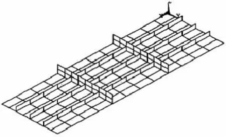
Fig.1 Hull grillage
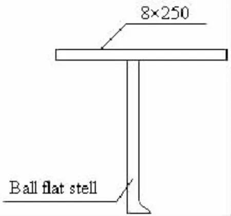
Fig.2 Stiffened panel cross section
General fatigue specimen design focuses on geometric similarity,load similarity andboundary condition similarity principles.Then the load provided by the fatigue testing machine is concentrated load,but the stiffened panel is subjected to distributed load.So the fatigue specimen design should consider three aspects:assessment section,loading section and connection section between the two.That is,a complete fatigue specimen made of the assessment section,the loading section and the transition section,shown in Fig.3.As can be seen from Fig.3,abrupt change phenomenon in the transition section is quite obvious[4].
The assessment section is the core section of specimen.The aim of the fatigue test is to obtain the fatigue life of the assessment section.Its design must meet certain principles,such as geometric similarity,load similarity and response similarity.
The loading section is to provide load,and ensure that load and boundary conditions of the assessment section meet test requirements.It is the additional part of specimen due to fatigue test load demand.In order to guarantee the success of fatigue test,the strength and stiffness of the loading section must be more than the assessment section,then resulting in the form of the loading section with different the assessment section.So the connection section inevitably appears abrupt change phenomenon,and causes stress concentration effects,shown in Fig.4.

Fig.3 Stiffened panel tensile fatigue specimen
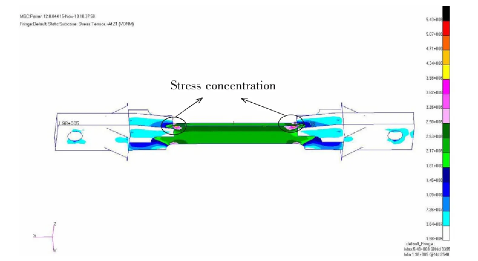
Fig.4 Fatigue specimen stress distribution
The transition section is to transfer load,and ensure that the test load can be effectively transferred to the assessment section.Then the stress flow in specimen can achieve the smooth transition.Yet,the transition section of stiffened panel specimen causes stress concentrationeffects due to abrupt change phenomenon,resulting in the region damage in advance.In order to ensure that the test is successful,based on fatigue cumulative damage theory,the fatigue specimen design should reserve a certain length of the transition section to meet reinforcement requirement in fatigue testing process.
2 Fatigue cumulative damage test method based on acoustic emission technology
Fatigue failure is a course of cumulative damage under fatigue load.So the fatigue cumulative damage theory studies fatigue damage cumulative rule and fatigue failure criterion under fatigue load.There is a typical Palmgren-Miner theory.Under cyclic loading,fatigue damage accumulation is linear,and when the accumulated damage reaches a certain value,the specimen may produce fatigue failure[6].At present,the fatigue strength check of the ship’s structure mostly uses this theory.
Following Palmgren-Miner theory,damage caused by a single cycle D1can be formulated as follows:

where N is the fatigue life under current load level.
Under constant amplitude loading,damage caused by n cycles Dncan be formulated as follows:

Under constant amplitude loading,when n is equal to N,fatigue failure occurs.Critical fatigue damage DCRis given to in the following forms:

In fatigue test,the transition section is the first region in specimen to be damaged.But the test is to obtain fatigue strength of the assessment section rather than the transition section.In order to effectively assess the fatigue strength of the assessment section,this paper presents the fatigue cumulative damage test method based on acoustic emission technology.The method solves the technical problems of traditional fatigue testing,to achieve the purpose of the fatigue test[2].The concrete implementing means is as follows:
(a)Tensile fatigue specimen is designed and manufactured according to the tensile fatigue specimen design method.
(b)According to testing requirements,a numerical simulation is carried out for the specimen before the fatigue test,and then the fatigue test program and acoustic emission monitoring program can be developed by the the numerical result.
(c)During fatigue test,acoustic emission technology is used to monitor crack initiation and propagation of the transition section.Once it discovers crack propagation,stop the test.Then crack part takes locally supplying strength measure.
(d)Fatigue tests continue at the same alternating stress.If it finds crack again,take step (c),until the assessment section fatigue failure.
3 Tensile fatigue test
In order to verify feasibility and applicability of the fatigue cumulative damage test method based on acoustic emission technology,tensile fatigue test was carried out for ship’s stiffened panel.According to the welding procedure of high-strength steel,preheating and post weld heat treatment should be taken to avoid weld cracks in the process of processing fatigue specimen.Processed specimen should be subject to non-destructive testing.Tensile fatigue test used sine wave load and constant stress amplitude control,as shown in Fig.5.The test load was maximum stress 418 MPa,stress amplitude 192 MPa.
When the fatigue-cycle times reached 6 695,acoustic emission monitoring interface discovered a large number of high amplitude intensive signal,as shown in Fig.6.This signal was characterized by large energy,high-frequency and short duration[3].The results showed that the transition section produced fatigue cracks,and it should be shut down and checked instantly.Inspection found the ball flat steel in the transition junction produced through cracks,asshown in Fig.7.So the fatigue test was suspended for the present,and the specimen was removed from the test machine.Then crack part in the ball flat steel took locally supplying strength measure,as shown in Fig.8.
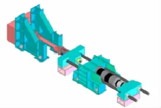
Fig.5 The sketch map of fatigue test
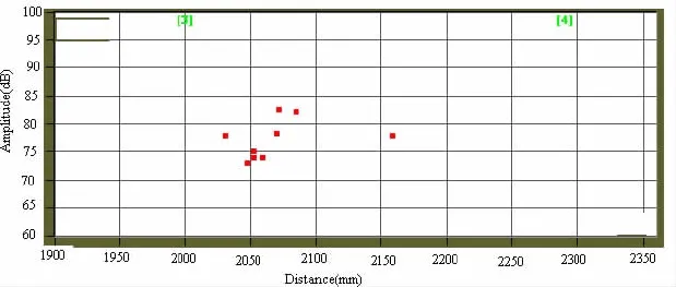
Fig.6 Fatigue crack acoustic emission signal diagram for the first time
After locally supplying strength,the fatigue test proceeded at the same alternating stress.When the fatigue-cycle times reached 10 562,acoustic emission monitoring interface discovered a large number of high amplitude intensive signal again,as shown in Fig.9.The results showed that the transition section produced fatigue cracks again, and it should be shut down and checked instantly[5].Inspection found the ball flat steel in the transition junction produced through cracks again,as shown in Fig.10.The fatigue test was suspended for the present,and the specimen was removed from the test machine again.Then crack part in the ball flat steel took locally supplying strength measure again,as shown in Fig.11.

Fig.7 Fatigue crack diagram for the first time
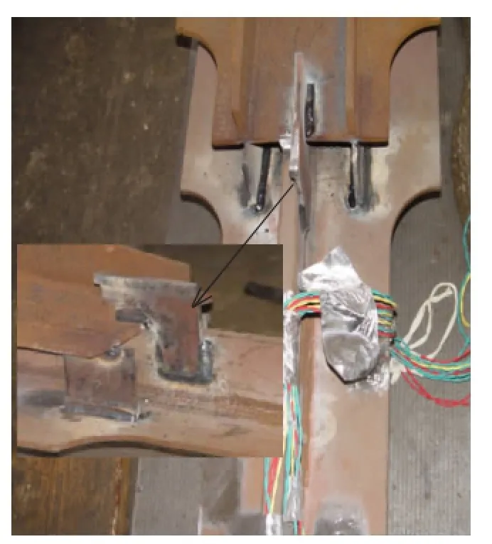
Fig.8Fatigue specimen strengthen form diagram for the first time
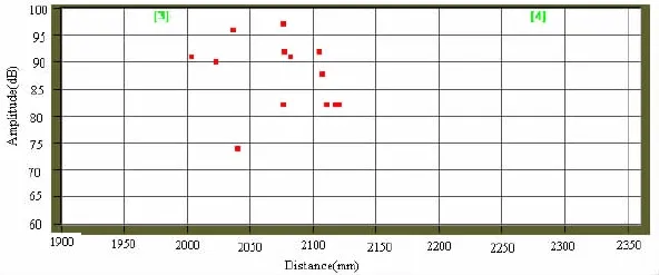
Fig.9 Fatigue crack acoustic emission signal diagram for the second time
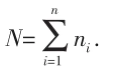
After locally supplying strength again,the fatigue test proceeded at the same alternating stress.When the fatigue-cycle times reached 3 452,the assessment section broke,as shown in Fig.12.According to Miner theory,under alternating load with maximum stress 418 MPa andstress amplitude 192 MPa,the total fatigue life of the stiffened panel was N=6 695+ 10 562+3 425=20 682.
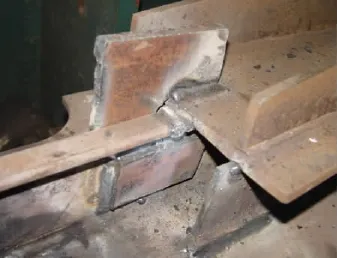
Fig.10 Fatigue crack diagram for the second time

Fig.11 Fatigue specimen strengthen form diagram for the second time
4 Conclusions
The paper takes stiffened panel for example,and makes a detailed study of the tensile fatigue test technology for stiffened panel by numerical calculation and test method.The tensile fatigue specimen design method of stiffened plate has been proposed.On this basis,according to the fatigue cumulative damage theory,combined with the acoustic emission dynamic crack detection technology,the fatigue cumulative damage test method based on acoustic emission technology is established for the first time.The method solves the technical problems of traditional fatigue testing,to achieve the purpose of the fatigue test.Finally,the feasibility and applicability of the method are verified by stiffened panel tensile fatigue test.The research results can provide technical guidance for similar structure fatigue test.

Fig.12 The assessment section fracture diagram
[1]Yao Weixing.Fatigue life prediction of structures[M].Beijing:National Defense Industry Press,2003:75-86.
[2]Yang Mingwei.Acoustic emission test[M].Beijing:China Machine Press,2005:5-20.
[3]Yue Yalin,Wei Pengyu,Li Shenghua,et al.Research on acoustic emission signature of fatigue cracks at titanium alloy weld joints[J].Journal of Ship Mechanics,2008,12(3):429-439.
[4]Zeng Qingbo,Yue Yalin,Wei Pengyu,et al.Research on the design method for tensile fatigue specimen of typical stiffened panel[J].Journal of Ship Mechanics,2012,16(5):585-591.
[5]Wei Pengyu,Yue Yalin,Zeng Qingbo,et al.Experimental study on the fatigue damage real-time monitoring of hull structure typical welded component[C]//Marine Steel Structure Branch of China Steel Construction Society 2012 Conference Proceedings,Xi’an,China,2012:275-284.
[6]Okawa T,Sumi Y,Mohri M.Simulation-based fatigue crack management of ship structure details applied to longitudinal and transverse connections[J].Marine Structure,2006,19:217-240.
典型加筋板拉伸疲劳试验方法
韦朋余,岳亚霖,曾庆波,张涛,张亦龙
(中国船舶科学研究中心,江苏无锡214082)
加筋板是船体结构的主要组成部分,针对船用加筋板试件在疲劳试验过程中连接段先于考核段破坏的技术问题,文章开展了加筋板拉伸疲劳试验技术研究,提出了加筋板拉伸疲劳试件设计方法。在此基础上,依据疲劳累积损伤理论,结合声发射动态裂纹检测技术,建立了基于声发射技术的疲劳累积损伤试验方法。通过加筋板拉伸疲劳试验验证了该方法的可行性和适用性,实现了疲劳试验的考核目标,可为以后类似结构疲劳试验提供方法参考。
疲劳试验;加筋板;声发射;累积损伤
U661.72
:A
韦朋余(1982-),男,中国船舶科学研究中心高级工程师;
1007-7294(2015)12-1517-08
U661.72
:A
10.3969/j.issn.1007-7294.2015.12.008
岳亚霖(1964-),男,中国船舶科学研究中心研究员;
曾庆波(1986-),男,中国船舶科学研究中心工程师;
张涛(1988-),男,中国船舶科学研究中心助理工程师;
张亦龙(1989-),男,中国船舶科学研究中心助理工程师。
Received date:2015-08-08
Foundation item:Supported by the Major State Basic Research Development Program of China(973 Program, No.2014CB046706)and Green Ship Technology Key Laboratory of Jiangsu Province
Biography:WEI Peng-yu(1982-),male,senior engineer of CSSRC,E-mail:wei_penyu@163.com; YUE Ya-lin(1964-),male,researcher.
猜你喜欢
杂志排行
船舶力学的其它文章
- Flows Around a Circular Cylinder Controlled by Electromagnetic Force at Subcritical Reynolds Numbers
- Mechanism Study on Tip Leakage Vortex in Ducted Propeller and a Method to Delay TLV Cavitation
- Ship Manoeuvring Performance and Construction of its Metamodels
- Hydrodynamic Force and Motion Response Analysis for Diver’s Ladder under the Disturbance of Mother Ship
- Study on the Dynamic Response and Tension Characteristics of a TLP with One Tendon Broken
- A New Concept of ETLP and Its Hydrodynamic Performance
