Tracking algorithm of BPSK signal in low bit SNR and high dynamic scenarios
2015-04-24WANGPeng王鹏CHENGuoying陈国瑛
WANG Peng(王鹏), CHEN Guo-ying(陈国瑛)
(Beijing Institute of Electronic System Engineering, the Second Academy of China Aerospace Science and Industry Corporation, Beijing 100854, China)
Tracking algorithm of BPSK signal in low bit SNR and high dynamic scenarios
WANG Peng(王鹏), CHEN Guo-ying(陈国瑛)
(Beijing Institute of Electronic System Engineering, the Second Academy of China Aerospace Science and Industry Corporation, Beijing 100854, China)
A new tracking algorithm is proposed aiming at the tracking problem in low bit signal-to-noise ratio (i.e., Eb/N0) scenarios, in which the bit clock regenerated by bit synchronization loop decides loop update moment. The double frequency processing and non-coherent accumulation technologies are applied to eliminate the impact of data polarity inversion, and then long time accumulation improves the input signal-to-noise ratio of discriminator. The frequency locked loop and phase locked loop constitute a carrier loop in parallel, which can meet the high dynamic demands. The effectiveness of this algorithm has been corroborated by theoretical analysis, simulation and measurements, and the new tracking algorithm has been used in an aerospace engineering project successfully.
tracking; double frequency processing; non-coherent; low bit signal-to-noise ratio
As the direct sequence spread spectrum (DSSS) signal has the advantages of high anti-interference performance and strong confidentiality, etc.[1], the DSSS signal system is widely used for information transmission in aerospace communication. Since spectrum is a scarce resource[2], it is hoped that every effective communication transmits information as much as possible with minimal bandwidth, and the data rate of future TT&C system will be up to 20 Mbit/s[3]. However, the disadvantages of DSSS signal including low data rate and high spectrum occupancy limit its application in certain occasions. Fortunately, binary phase shift keying (BPSK) signal has the characteristics of high data rate and high spectrum utilization rate, which is adaptable to some future development of the aerospace industry.
In aerospace communications, high-speed movement of aircraft and increased distance of signal transmission will lead to the following problems. Firstly, a high-speed movement of the aircraft results in a larger Doppler frequency with the acceleration of 10g[4]or even more. The dynamic adaptability of conventional tracking algorithm can no longer meet the requirements. Secondly, with the detected distance becomes farther, the received power of signal is weakened, and bit error rate (BER) is increased. In order to reduce the BER, the Consultative Committee for Space Data Systems (CCSDS) recommends adopting channel-coding technology[3]. While the data rate is further increased after being encoded with this technology, it is accompanied with additional problems——longer loop update period for improving the input signal-to-noise ratio (SNR) of discriminator will lead to data polarity inversion during the loop update period. Ref. [5] provided a BPSK signal demodulation technology based on maximum likelihood estimator. Refs.[6-7] studied BPSK signal demodulation by Costas loop. However, these references demand a relatively high bit SNR (denoted by Eb/N0) of BPSK signal, which cannot meet the requirement of high data rate and weak signal tracking. In view of the data modulation, Ref. [8] combined bits to maximize the signal energy during the coherent integration. In order to traverse all the possible bit combinations, tracking time increases exponentially with the amount of data bit. Therefore, this method has poor real-time property, which is not suitable for high dynamic scenarios.
Taking an S-band satellite communication link for example, with conditions of the minimum carrier-to-noise ratio (CNR) of 60 dBHz, the data rate is approximately 3 Mbit/s after being encoded upon using the Turbo code of 1/3 rate recommended by CCSDS with the required uncoded data transmission rate of 1 Mbit/s, the maximum Doppler frequency of 100 kHz, and the Doppler change rate of 5 kHz/s. Therefore, the Eb/N0 of this communication link is -4.77 dB. If the loop update period is 0.1 ms without any processing, there will be 300 times of data polarity inversions within the loop update period to the greatest extent. The data polarity inversion and high dynamic environment will result in conventional tracking loop working improperly[9].
For the data polarity inversion phenomenon within the loop update period under low Eb/N0, and the high dynamic environment, this paper firstly analyzes the conventional BPSK signal tracking algorithm, and then proposes a novel tracking algorithm and the effectiveness of this algorithm has been corroborated by theoretical analysis, simulation and measurements.
1 Conventional BPSK tracking algorithm
1.1 Signal model
In the receiver, intermediate frequency (IF) digital BPSK signal obtained by down-conversion and A/D sampling process can be expressed as
s(ti)=A(ti)d(ti-τ)cos [2π(fI-fd)ti+φ0]+n(ti)
(1)

(2)
1.2 Conventional algorithm
Conventional BPSK signal tracking loop comprises a carrier tracking loop and bit synchronization loop. For instance, the tracking loop in Ref. [10] consists of a Costas PLL and a bit synchronization loop constituted in parallel. The receiver obtains the BPSK signal and accomplishes the down-conversion and integrate-and-dump (I&D) processing. The identification error is extracted by the arctangent phase discriminator and timing error discriminator. Respectively, the results of loop filters are sent to the carrier numerically controlled oscillator (NCO) and data digital controlled oscillator (DCO), so that the error between the input signal and local signal is trimmed off. Finally synchronization of the signals is achieved. The tracking loop diagram is shown in Fig.1.

Fig.1 Conventional BPSK signal tracking
The down-converted results expressed as
Id(i)=A(iTs)d(iTs-τ)cos (ΔωdiTs+Δφ)+nI(i)
(3)
Qd(i)=A(iTs)d(iTs-τ)sin (ΔωdiTs+Δφ)+nQ(i)
(4)
are obtained by multiplying the BPSK signals(ti) with local NCO output of sine and cosine signal. Where Doppler estimation bias is Δωd=ωd-d, phase estimation bias is Δφ=φ0-0,nI(i) andnQ(i) are noises.
The I&D results are
(5)
(6)
whereNis the number of sampling points within an integration time, thus,T=NTsrepresents the integration time, i.e. the loop update period. Generally, no sign transition exists within the integration time, therefore, the data polarity of the samples for summation and that of the summation result can be represented byd[(k-1)NTs-τ], which is abbreviated asdk, uniformly in Eqs.(5)(6).
1.3 Disadvantages of conventional algorithm
Input SNR of discriminator can be improved by I&D. The SNR after I&D, denoted asηi, is calculated by
ηi=ζ-10log10(1/T)
(7)
Eq.(7) shows thatηiis jointly determined by the CNR of input signal and the loop integration time. The lower the CNR is, the longer integration time is needed to obtain an identical performance.
Generally, the conventional tracking algorithm selects the symbol duration as the integration time[9], to avoid data polarity inversion during the integration time. However, the SNR after integration is limited to the Eb/N0, which may hardly meet the requirement of discrimination. Therefore, to improve the input SNR of discriminator, it is necessary to prolong the integration time. Conventional tracking algorithm doesn’t deal with the data modulation. The energy cannot be normally accumulated in presence of data polarity inversion. Therefore, it cannot meet the demand of BPSK signal tracking in low Eb/N0 scenarios.
The Costas loop, which is widely used in carrier phase tracking, is not sensitive to the sign transition. It can produce the most accurate phase tracking, but is sensitive to the dynamic stress[10]. In the following section, the BPSK signal tracking loop fitting for high dynamic and low Eb/N0 scenarios is analyzed.
2 Tracking algorithm of low Eb/N0 BPSK signal
In this section,a tracking algorithm for high dynamic and low Eb/N0 BPSK signal is proposed. At first, three key operations involved in this algorithm are introduced respectively, which are double frequency processing, non-coherent accumulation and bit synchronization. And then the structure of the improved tracking algorithm is presented.
2.1 Key operations involved in the proposed algorithm
2.1.1 Double frequency processing
Double frequency processing equipped with square processing can eliminate the influence of data polarity inversion. The design of FLL including double frequency processing is shown in Fig.2. Square processing as the key part of double frequency processing is shown in the dashed box.
IF NCO generates two branches orthogonal sinusoidal signals with IF frequency offI. Thus, withA(iTs)=1,φi=ωdiTs+Δφ, the BPSK down-converted signals containing Doppler frequency information are

Fig.2 Diagram of FLL including double frequency processing
Ii=d(iTs-τ)cos (φi)+nI(i)
(8)
Qi=d(iTs-τ)sin (φi)+nQ(i)
(9)
After double frequency processing using trigonometric formulas, the mathematical expressions are
(10)
(11)
Sinced(t) is 1 or -1,d2(iTs-τ)=1. Thus, double frequency processing can eliminate the influence of the data modulation. NCO generates two branches orthogonal sinusoidal signals with a frequency of 2d. Then after down convention processing, the expression of signals are
Id=IY,icos (2diTs)+QY,isin (2diTs)=cos [2(ωd-d)iTs+Δφ]+nI
(12)
Qd=QY,icos (2diTs)-IY,isin (2diTs)=sin[2(ωd-d)iTs+Δφ]+nI
(13)

Fig.3 Non-coherent accumulation diagram
Thekth I&D results can be expressed as
(14)
(15)
whereθk=(k-1/2)NTs2Δωd(k)+2Δφ.
Taking advantage of square processing, loop integration time of FLL needs not be restricted by the symbol duration, making it possible to improve the SNR and consequently the accuracy of the loop tracking. However, square processing would eliminate the modulation information. Therefore, non-coherent accumulation is also needed for data demodulation which is introduced in the next subsection.
2.1.2 Non-coherent accumulation
Non-coherent accumulation is achieved by estimating the sign of cumulative result within a data bit, and using the data sign estimation to correct the sign of cumulative result. Accumulation after sign correction not only removes the influence of the data polarity inversion, but also maintains the original data information. The realization is shown in Fig.3.
The expressions of I&D results are
(16)
(17)
In this case,TIDequals 1/fR, and the sample numbers within a data bit isN=fs/fR. When completely synchronized, Δωd≈0 and sinc(NTsΔωd/2)≈1. Thus, the above equations after normalization can be rewritten as
Ip(k)=dkcosψ+n′I(k)
(18)
Qp(k)=dkcosψ+n′Q(k)
(19)
whereψ=(k-1/2)NΔωd+Δφ.
If the PLL carrier demodulation results are accumulated directly, ignoring the data polarity inversion, the energy of the accumulation result will be countervailed. Therefore, sign decision is necessary before accumulating the carrier demodulation results across data bits. The influence of the data modulation can be eliminated using the result of sign decision by
Ip,k=kdkcos (ψk)+kn′I(k)
(20)
Qp,k=kdksin (ψk)+kn′Q(k)
(21)

Fig.4 Pulse of bit synchronization loop
2.1.3 Bit synchronization
The sign estimation used in non-coherent is obtained by bit synchronization, which is introduced in this subsection. Bit synchronization loop makes an accumulation within a symbol duration under the control of produced in-phase periodic pulse and mid-phase periodic pulse separately. In-phase I&D result is the accumulation of I-branch carrier demodulation results within adjacent in-phase periodic pulse. In the same way, mid-phase I&D result is corresponding to the mid-phase periodic pulse. Then phase error discrimination is made by way of in-phase & mid-phase method. When bit synchronization loop is completely locked, the in-phase periodic pulse is located in the starting of a data bit, and the mid-phase periodic pulse is located in the middle of a data bit.
The estimated delay error between the regenerated in-phase pulse with the actual data is Δτ=τ-, whereis the estimated delay of bit synchronization loop. During the same data period, the data sign is unchanged, so that, takenas the nearest integer of (|Δτ/Ts|)(|Δτ|/Ts≤N/2). As shown in Fig.4, Δτis assumed positive, which means the regenerated phase lags behind the phase of the signal source. When FLL and PLL are locked,in Eq.(8). Ignoring the effects of noise, the results of in-phase I&D and mid-phase I&D are
(22)
(23)
where
Dp1(k)=d[(k-1)NTs-τ]Dp2(k)=d[(kN-1)Ts-τ]De1(k)=d[(kN-3/2N)Ts-τ]De2(k)=d[(kN-1-N/2)Ts-τ]
When the data polarity inversion occurs, if bit loop is non-synchronous, mid-phase I&D result is not zero and increases with the estimated delay error. The loop phase error is
(24)
When the data is reversed, the right result of the identification is obtained, which is
(25)

Fig.5 Tracking block diagram of new algorithm
Similarly, when the local synchronous clock is advanced, identification error is
(26)
2.2 New tracking algorithm
In the tracking algorithm proposed, a native bit synchronous clock is selected as the reference to set loop update period. Double frequency processing eliminates the influence of data polarity inversion during a FLL loop update period, and non-coherent accumulation remove the influence of data modulation in a PLL loop update period to improve the input SNR of the discriminator. Such processing can solve the problems caused by data polarity inversion in the conventional tracking loop. In view of the dynamic adaptability of the tracking algorithm, FLL and PLL work in parallel, and PLL is assisted by FLL in this paper. Improved tracking block diagram is shown in Fig.5. The loop gradually achieves synchronization under the control of synchronous clock accompany with the regeneration of data.
3 Performance analysis of the proposed BPSK signal tracking algorithm
Double frequency processing and non-coherent accumulation are used to deal with data modulation. However, they will result in performance loss comparing with coherent accumulation. The following part will give some qualitative performance analysis.
3.1 Square loss in FLL
To eliminate the influence of data modulation, double frequency processing is required, which is equivalent to the square of the signal. Thus operation will result in a certain loss of SNR. The SNR loss denoted asηLis expressed as[11]
ηL=10log10(4+2/(10η/10))
(27)
whereηdenotes the SNR of the input signal filtered by IF band-pass filter with a bandwidth of 2fR. Therefore, it equalsζ-10log10(2fR).
After non-coherent accumulation, the input SNR of discriminator denoted asηois
ηo=ζ+10log10T-ηL
(28)
whereTis the loop update period. Eq.(28) shows a linear relationship between the signal power after double frequency processing and the SNR of input signal. Ref.[12] indicated the computational formula of frequency error of FLL caused by thermal noise as
(29)
whereFequals 2 in the low Eb/N0,Tis the integration time, andBLis the loop bandwidth. Thus, without data polarity inversion, FLL performance curves under 0.1 ms coherent and non-coherent accumulation are illustrated in Fig.6.

Fig.6 FLL performance curves under 0.1 ms coherent and non-coherent accumulation
Fig.6 shows that non-coherent accumulation, which is not sensitive to data modulation, has SNR loss caused by square operation in return.
3.2 Non-coherent loss in PLL
Because of the estimation error of data sign, non-coherent accumulation in PLL brings about some SNR loss, which is related to BER. Ref. [11] proposed the simplified computational formula of SNR loss caused by non-coherent accumulation, expressed as
ηL=-20log10(1-2Pe)
(30)
wherePeis the BER of BPSK signal, which can be calculated by
(31)
whereθkis the average carrier phase error, which can be treated as zero ideally. In addition, the SNR afterMtimes non-coherent accumulation is
ηo=ηi-ηL+10log10M
(32)
PLL error caused by the dynamic stress can be ignored because PLL is assisted by FLL. The specific analysis isdetailed in Ref. [13]. The performance of bit synchronization loop is analyzed by formulas in Ref. [14]. The SNR loss before discrimination can be calculated by Eq.(27) and Eq.(30). The parameters and theoretical precision of the tracking loop are given in Tab.1.

Tab.1 Theoretical precision values of various loop
Although double frequency processing and non-coherent accumulation in PLL bring about some loss of SNR, they eliminate the influence of data modulation as well. Therefore, multi-data bits accumulation can be achieved under the condition of low Eb/N0. Hence, the input SNR of the discriminator is above threshold. Ultimately, accurate tracking of the carrier and data phase can be achieved.
4 Algorithm verification
4.1 Simulation verification
In order to verify the effectiveness of the tracking algorithm of the BPSK signal with low Eb/N0 and high dynamics, the tracking parameter is set as follows. Parameters of tracking loop are selected according to Tab.1. The sample frequency is 60 MHz, and the rate of the encoded data to be transmitted is approximately 3 Mbit/s. The Doppler change rate is 5 kHz/s, and the initial Doppler frequency deviation is 500 Hz. Simulation result is shown in Fig.7. It is indicated that the loop works stably. Phase error of PLL and the bit synchronization loop are both eventually stabilized at the vicinity of 0.
The statistical analysis of the simulation results under different CNRs is shown in Tab.1. When the CNR is as low as 60 dB·Hz, the carrier phase error of the receiver is not greater than 1°, and the data phase error is not greater than 2°, which is corresponding to the theoretical analysis in Tab.1. In Tab.2, energy loss is calculated with respect to the phase error of 1σ.

Fig.7 Simulation result under CNR of 60 dB·Hz
Tab.2 Statistical analysis of the simulation results under different CNRs
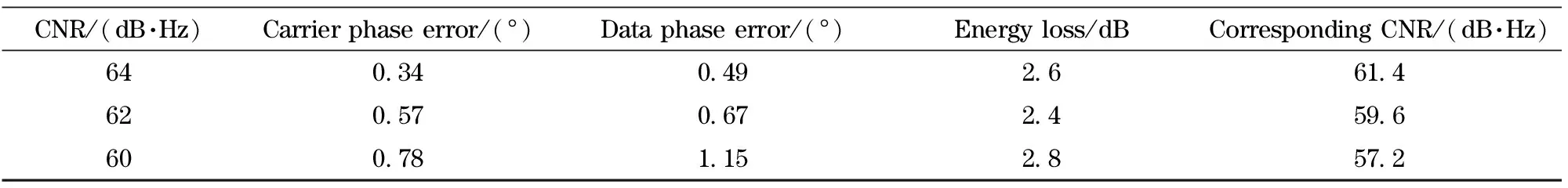
CNR/(dB·Hz)Carrierphaseerror/(°)Dataphaseerror/(°)Energyloss/dBCorrespondingCNR/(dB·Hz)640 340 492 661 4620 570 672 459 6600 781 152 857 2
The performance as shown in Tab.2 decreases slightly than that in Tab.1 because of the synchronous deviation of data synchronization loop. In line with the comparison between the tracking loop proposed and the conventional Costas tracking loop (specifically the arctangent phase discriminator as an example), their performances under different CNRs are presented in Tab.3.

Tab.3 Tracking performances under different CNR conditions
Tab.3 shows that, conventional Costas tracking loop withTIDequal to symbol duration cannot lock when CNR is not bigger than 62 dB·Hz. In the higher CNR scenarios, the precision of conventional Costas tracking loop is still inferior to the proposed one with the contribution of non-coherent accumulation.
4.2 Measurement verification
In view of the characteristics of the aerospace communication tracking algorithm, an FPGA is chosen to implement the tracking algorithm (XC5VSX95T-2 type of Virtex5 series, from a large-scale Xilinx Inc), with comprehensive synthesis tool ISE 11.1. The hardware resources consumption is shown in Tab.4, with some multipliers and other resources used by time-division multiplexing. The device utilization of the conventional Costas tracking loop is also analyzed as a comparison in Tab.4.

Tab.4 Device utilization comparison
It shows that, the hardware resources consumption in implementation of the tracking loop proposed does not increase a lot. Especially, considering the tracking performance improvement, the increase of resources consumption is acceptable.
BER tester validates the proposed algorithm. The measured error rate results are summarized in Tab.5, which are consistent with the theoretical values of BER.

Tab.5 Measured error rate results
5 Conclusion
This paper proposes a new tracking algorithm. The loop update period of carrier loop depends on the regenerated bit clock. The carrier loop is constituted by FLL and PLL in parallel, which frequency-locked loop using double frequency processing and phase-locked loop using non-coherent accumulation eliminate data polarity inversion. Thus, BPSK signal carrier tracking and data demodulation are achieved under high dynamics, and low Eb/N0 conditions. The effectiveness of the algorithm was verified by the theoretical analysis, simulation and measurements. The proposed algorithm is applicable to the high data rate BPSK modulated communications. And it can promote a combination between high-speed data communications with telemetry and navigation, especially merged downlink ranging and telemetry in aerospace systems.
[1] Emmanuele A, Zanier F, Boccolini G, et al. Spread-spectrum continuous-phase-modulated signals for satellite navigation[J]. IEEE Transactions on Aerospace and Electronic Systems, 2012, 48(4): 3234-3249.
[2] Xie Z, Ma L, Liang X. Unlicensed spectrum sharing game between LEO satellites and terrestrial cognitive radio networks[J]. Chinese Journal of Aeronautics, 2012, 25(4): 605-614.
[3] Calzolari G P, Chiani M, Chiaraluce F, et al. Channel coding for future space missions: new requirements and trends[J]. Proceedings of the IEEE, 2007, 95(11): 2157-2170.
[4] Yao Z, Cui X, Lu M, et al. Dual update-rate carrier tracking technique for new generation global navigation satellite system signals in dynamic environments[J]. IET Radar, Sonar & Navigation, 2009, 3(3): 203-213.
[5] Rabiei A M, Beaulieu N C. Exact error probability of a bandlimited single-interferer maximum-likelihood BPSK receiver in AWGN[J]. IEEE Transactions on Wireless Communications, 2007, 6(1): 30-34.
[6] Maya J A, Casco N A, Roncagliolo P A, et al. A high data rate BPSK receiver implementation in FPGA for high dynamics applications[C]∥Programmable Logic (SPL), 2011 VII Southern Conference on, Cordoba, Argentina, 2011: 233-238.
[7] Hu Y, Sawan M. A fully integrated low-power BPSK demodulator for implantable medical devices[J]. IEEE Transactions on Circuits and Systems I: Regular Papers, 2005, 52(12): 2552-2562.
[8] Soloviev A, Van Graas F, Gunawardena S. Decoding navigation data messages from weak GPS signals[J]. IEEE transactions on Aerospace and Electronic Systems, 2009, 45(2): 660-666.
[9] Razavi A, Gebre-Egziabher D, Akos D M. Carrier loop architectures for tracking weak GPS signals[J]. IEEE Transactions on Aerospace and Electronic Systems, 2008, 44(2): 697-710.
[10] Gardner F M. A BPSK/QPSK timing-error detector for sampled receivers[J]. IEEE Transactions on Communications, 1986, 34(5): 423-429.
[11] Luo Yu, Wang Yongqing, Wu Siliang, et al. Phase estimation for weak GPS signal based on incoherent integration[J]. Transactions of Beijing Institute of Technology, 2013, 33(1): 93-98. (in Chinese)
[12] Lashley M, Bevly D M, Hung J Y. Performance analysis of vector tracking algorithms for weak GPS signals in high dynamics[J]. IEEE Journal of Selected Topics in Signal Processing, 2009, 3(4): 661-673.
[13] Juang J C, Chen Y H. Phase/frequency tracking in a GNSS software receiver[J]. IEEE Journal of Selected Topics in Signal Processing, 2009, 3(4): 651-660.
[14] Borio D, Mongredien C, Lachapelle G. Collaborative code tracking of composite GNSS signals[J]. IEEE Journal of Selected Topics in Signal Processing, 2009, 3(4): 613-626.
(Edited by Cai Jianying)
10.15918/j.jbit1004-0579.201524.0117
TN 911 Document code: A Article ID: 1004- 0579(2015)01- 0118- 10
Received 2014- 09- 14
Supported by the National High Technology Research and Development Program of China (863 Program) (2011AA1569)
E-mail: wp_fuyao@163.com
猜你喜欢
杂志排行

Journal of Beijing Institute of Technology的其它文章
- Investigation of the optimum differential gear ratio for real driving cycles by experiment design and genetic algorithm
- Effect of juglone on immunity response and oxidative stress in mice
- Birkhoff symmetry and Lagrange symmetry
- Preparation of polyimide/LDH nanocomposites and characterization of their properties
- New scheme of dynamic traitor tracing against the immediate rebroadcast attack
- Construction method of Chinese sentential semantic structure