基于有限元法的汽车变速器齿轮与轴承优化
2015-04-10采埃孚中国投资有限公司上海201615
(采埃孚(中国)投资有限公司,上海 201615)
基于有限元法的汽车变速器齿轮与轴承优化
(采埃孚(中国)投资有限公司,上海 201615)
采埃孚集团开发和生产了种类繁多的传动齿轮。对于齿轮的优化和可靠设计,有限元法是尤为适合的。而且,这种方法能容易集成于采埃孚的程序系统。本文展示了在开发过程中如何运用该方法进行齿轮优化。此外,文中多处演示了齿轮和轴承之间的相互作用。这也是采埃孚集团致力于开发轴承计算的原因。文中实例展现了如何优化滚动轴承以达到理想的齿轮接触印痕。当然,这些优化方法也适用于传动齿轮。
变速器 齿轮 轴承 有限元 优化
1 采埃孚变速器的应用范围
采埃孚为多种发动机输出及装置开发相应的变速器,应用范围涵盖从乘用车如9档自动变速器,到重型卡车变速器和风力发电用变速器。同时,采埃孚也为飞机,客车和工程机械开发变速器产品。由于安全性要求、温度范围、扭矩及速度范围、人员舒适性、驱动形式和传动效率水平的差别,各应用领域的设计要求也有所不同。下文采用了统一的有限元方法进行优化。
2 齿轮和轴承计算方法开发
在上文所提到的各个应用领域中,需要大量不同形式的变速器。这些不同的变速器的设计结合了大量不同的齿轮、轴承、材料,并具有相互限制的设计要求。因此,精确和高效的计算十分关键。通常单个零件或整个变速器都必须满足相当高的舒适性或承载能力要求,所以也需要考虑所有零部件间的相互作用。按照采埃孚的观点,有限元法能够提供解决这类问题的基本条件。为了保证流程的高可靠度。
1 Application fields of ZF transmissions
ZF develops transmissions for a large range of engine outputs and applications. Application fields range from passenger car applications with 9-speed automatic transmissions, to heavy truck transmissions, and wind turbine gearboxes. ZF also develops transmissions for aircraft, buses and industrial engineering applications. Therefore, the requirements of the individual application fields result from different safety requirements, temperature ranges, torque and speed ranges, comfort, driveline types, and high degrees of efficiency. In the following paper a uniform method for optimization using FEM will be presented.
一套独立的流程被用于齿轮和轴承的复杂网格划分。根据齿轮和轴承的设计要求,单独运行的软件会生成网格化的齿轮和轴承模型。这套独立流程的一个优点是提供了可无缝调用的文档,包含了所用到的齿轮和轴承参数。各项相关内容都集成于这个总体模型之中。此外,我们使用了自有的标准化程序以系统地确定分析范围,取代了对现有的前处理器的结果分析。
3 对有限元法的要求
现代的硬件平台和求解器不仅能具有高可靠性和高可用性,也能求解相当大型的有限元模型和复杂的接触问题。在采埃孚集团公司内部各不同领域的变速器开发中都采用了有限元法。通过按实际任务调整原有的有限元模型,可以使流程得以简化。除了产生刚度的宏观几何,在所有接触问题中的一个重要因素是接触区域的精确映射。要确保计算结果的质量,零件或者接触区域表面的网格划分必须遵循特定的标准。例如,网格划分不能造成明显的结果偏差。为了达到噪声和(或)应力分析的目标结果,接触区域通常会被直接修正。作为一个可选项,对齿根刚度的优化能够附带地满足减重需求。因此,通过开发我们自己的有限元工具和分析方法,保证了更加高效的前处理和后处理。
使用有限元法并分析较大的工作区域使得我们能深入分析齿轮和轴承的噪声水平和承载能力。这其中同时考虑了齿根刚度和接触刚度。通常,实现承载能力和噪声水平的平衡是最终的目标。通过接触分析能够检验各不同影响变量之间的相互作用。
4 对齿轮和轴承计算的要求
只有确定了接触几何模型才能得到关于承载能力和噪声水平的可靠描述。除了基本齿轮参数外,我们还需要修形和齿廓修形等参数。这些参数一般是来源于设计(或测量数据)。
接触定义是基于标准的面对面接触和点对点接触。网格划分的精细程度是不受几何尺寸的影响的,在需要时还能进行调整。和齿轮本体的连接可以采用MPC(共节点约束)。
2 Method development for gearing and bearing calculation
These fields of application require a wide range of transmission types. This, combined with a large number of different gearings, bearing concepts, materials, and often contradictory requirements for use, makes an equally precise and efficient calculation method essential. Frequently, individual parts or transmission systems must meet very high standards of comfort or load-bearing capacity, therefore it is necessary to take into account the interaction of all components. In the view of ZF, FEM provides the basic conditions to ensure this. To guarantee high process reliability, the basic transmission is designed using a commercial pre-processor. A separate process chain is used for the complex meshing of the gearing and the bearing. Independent programs create the meshed gearings and bearings according to the requirements of the gearing and bearing design. The process chain described has the advantage of providing a seamless documentation of the gearing and bearing data used. The various items are precisely integrated in the overall model. Evaluation of the results with available post-processors is replaced by our own standardized routines that systematically access a certain evaluation area.
3 Requirements of the FE method
Apart from offering high process reliability and availability, modern hardware platforms and solvers are capable of solving very large FE models and complex contact problems. The Group-wide application of the FE method in various areas of transmission development makes it easier to adapt already existing FE models to our own tasks. An important factor in all contact analyses is not only the macro-geometry that creates rigidity, but also precise mapping of the contact areas. To ensure a comparable results quality it is necessary to follow standards when meshing parts/contact surfaces, i.e. the meshing must not have any significant effect on the results. To achieve the objective of a noise and/or stress analysis, the contact area is often di-
高效的接触求解器能够以通用的ASCII格式输出结果。
4.1 前处理(图1+图2)
除了常用的圆柱齿轮(及有径向跳动的轴体齿形),变厚齿轮也能使用自动化的方式进行网格划分。需要使用的齿轮参数可以通过对外接口从设计环节中获取,然后按照所要求的网格划分精细程度,就可以生成齿轮模型。可供选择的不仅有精细划分的齿轮网格以用于啮合工况仿真,也有较粗大的网格以用于刚度仿真。如果有需要,还可以使用混合密度的网格。对于更复杂的齿轮网格划分(锥齿轮、花键、啮合齿轮),可以使用半自动化的方法。
rectly corrected, and the optimization of the surrounding rigidity is an option which additionally meets the demand for weight-saving solutions. Therefore, the development of our own FE tools and evaluation routines ensures more efficient pre and post-processing.
Using the FE method and evaluating a large operational area mean that we can analyze in depth the effects on the noise levels and load-bearing capacity of gearings and bearings. Both the surround-ing rigidity and the contact rigidity are taken into account here. The objective is very often finding a compromise between load-bearing capacity and noise. The contact analysis makes it possible to examine the interplay between individual influencing variables.
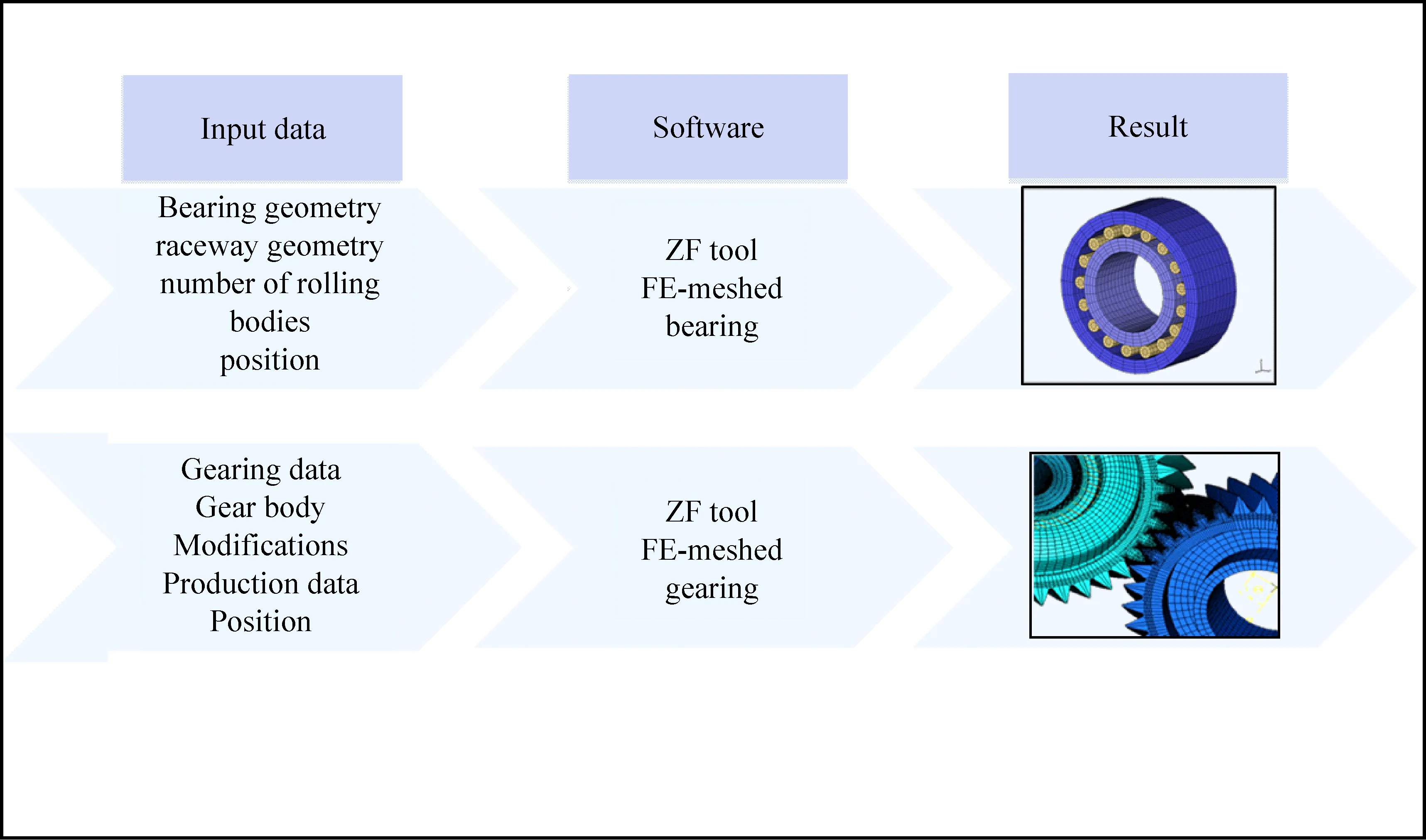
图1 有限元结构自动生成器的协作流程图
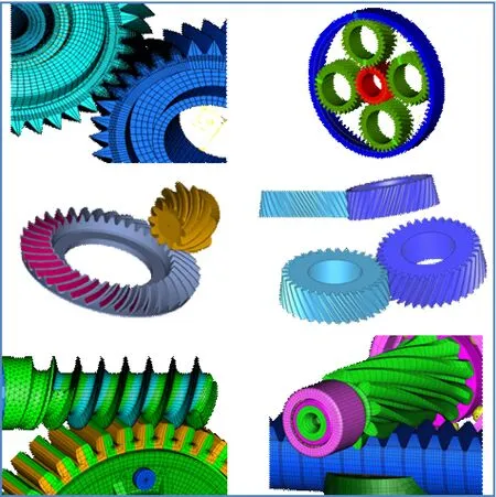
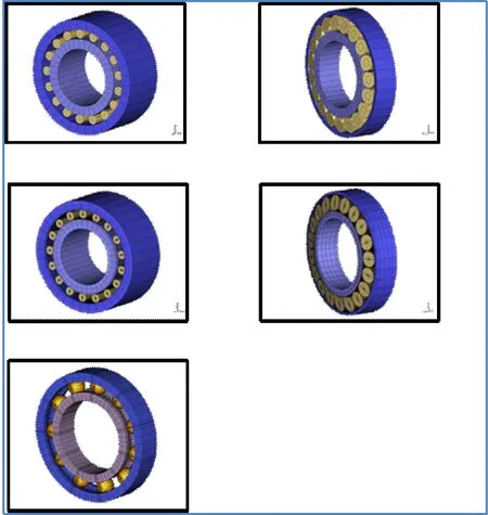
图2 采埃孚的齿轮和滚动轴承有限元模型
可作分析的轴承类型有圆柱滚子轴承、向心滚子轴承和球轴承。轴承的几何参数来源于从轴承选型手册或供应商图。轴承滚道形状应由供应商提供或由测量得到。
4.2 后处理(图3)
除齿根应力外,还能对作用于啮合作用线方向的齿面应力进行分析。这涉及到了在各个接触位置下的所有应力值。通过分析能够确定在被分析区域的最大或最小应力分布。可以使用低扭矩和高扭矩来得到不同的应力分布结果。此外,除了局部应力的分析, 同时也应进行寿命计算分析。
齿面方向的螺旋角修正也是用我们自有的分析软件来确定的。在此之前定义了与已知接触面和齿向相关连的节点,从其发生的变形可得到螺旋角修正的建议值。在一定的载荷范围内,可以得到螺旋角修正的变化梯度。而载荷变化时的齿面接触应力结果可以用螺旋角修正的梯度算出。
对轴承计算而言,从接触力和已知的圆角和曲线可以计算得到压应力。再考虑到损坏发生的位置和应力循环,就能确定轴向和径向的最大损伤程度。通过调整轴承内外圈的接触间隙能够有效地影响接触压应力。无安装间隙能够避免轴承损伤或者能提高工作性能。除了上述的自有优化方案,我们也采用有限元优化的商业软件来优化刚度和重量。
4 Requirements of gearing and bearing calculations
Reliable statements on load-bearing capacity and noise emissions are only possible with precisely determined contact geometries. Apart from the general gearing data, we need corrections and modifications. Usually, these are available during the design (or otherwise from measurement data).
The contact definition is based on standardized contact values for both surface-to-surface contacts as well as node-to-node contacts. The meshing fineness is independent of size and can be modified if necessary. An MPC (multi-point constraint) can be used for connection to the gear body.
An efficient contact solver supplies the results in a usable Ascii format.
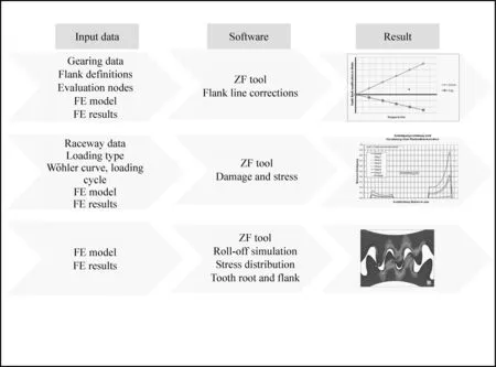
图3 对齿轮和滚动轴承的有限元分析流程
5 应用实例
在本节的应用实例中,我们将通过一个滚动仿真实例和一个轴承计算实例来展示采埃孚软件的能力。
在滚动仿真中(图4),轴和齿根的刚度都已确定。通过使用采埃孚的齿轮前处理器,可以由包括螺旋角修正的内部加工参数得到有限元网格模型。齿轮模型被置于总体模型中的特定位置。因此,接触对象、载荷和边界条件都有待输入。通过变换齿轮的节点坐标,可以得到更多的计算模型。本例在一个径节距上进行了10点平均分布的滚动位置分析。计算结果是接触宽度内的齿面应力分布和齿根应力值。在这个简单的圆柱齿轮传动链模型中表明,在所选的载荷工况下螺旋角修正选用合理。为了正确记录壳体和轴的变形对齿向修形的影响,滚动仿真都是使用整体模型,及/或使用转化了边界条件的简化子模型。
对于行星齿轮组,齿轮周节误差及公差对于轴承的影响更为复杂。下面以一个行星齿轮的轴承为例。
4.1 Pre-processing (Fig.1+2)
Apart from the spur gears mainly used (also shaft gearing with runout), beveloids can also be meshed in an automated way. The necessary gearing data is accessed from the design process via an interface and the gearing is generated with the required meshing fineness. Possible options are not only tightly meshed gears for simulating the meshing conditions but also loose meshing for simulating rigidity. If required, a mixture of degrees of mesh density can be used. Semi-automated processes are available for further gear cutting methods (bevel gears, drive gearing, meshing gears).
The bearing types available are cylindrical roller, taper roller, and ball bearings. The input data for the bearing geometry is taken from bearing catalogs or supplier drawings. Raceway profiles are either stated by the bearing supplier or derived from measurements.
4.2 Post-processing (Fig.3)
Apart from root stress, flank stress over the line of contact can be analyzed.
This involves evaluating any number of individual contact positions. The analysis then determines the distribution of the maximum/minimum stresses in the analyzed area. This allows a valua-tion of the stress distribution for both low and high torques. In addition to the local strain approach, a durability analysis can also be performed.
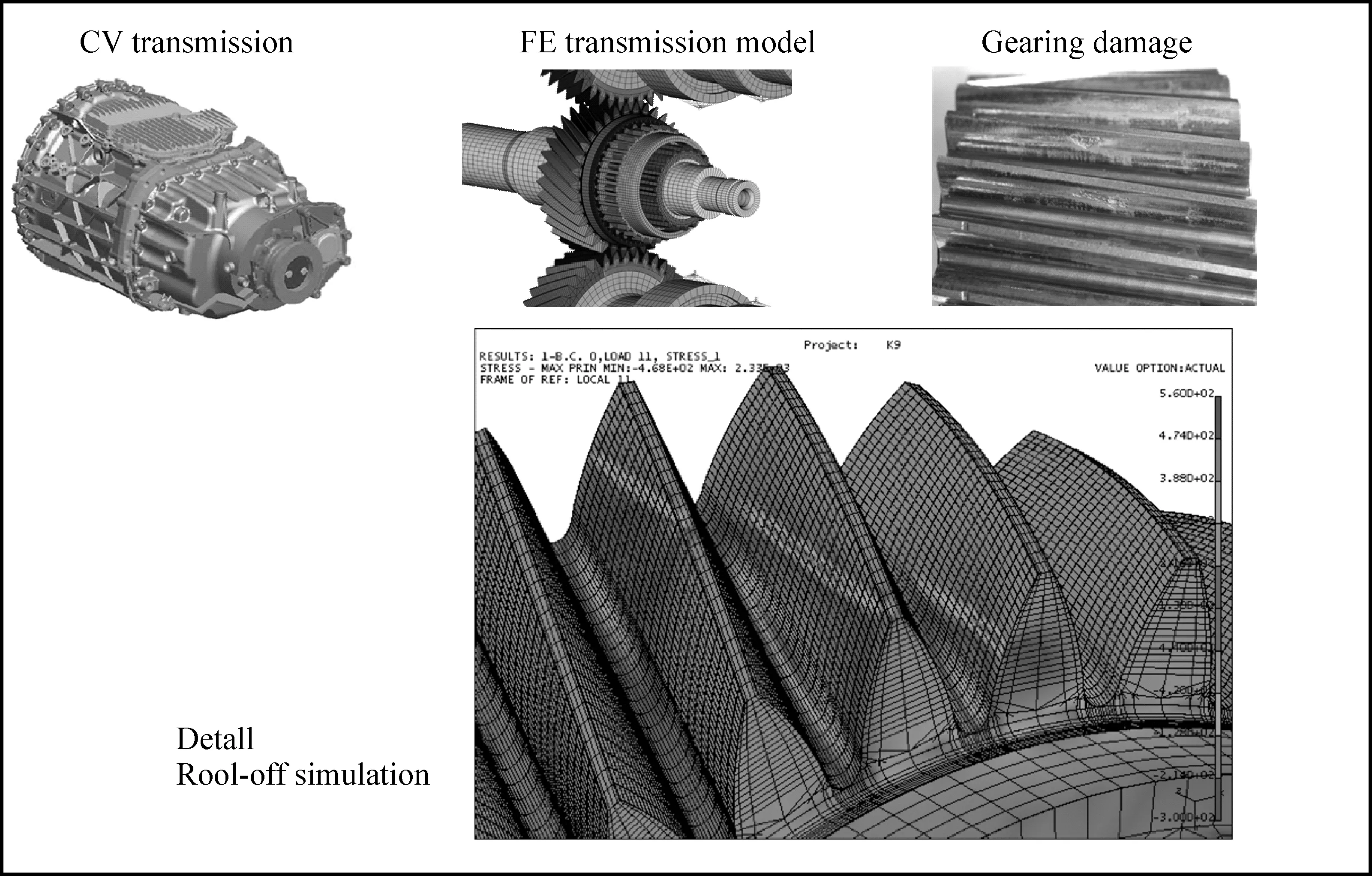
图4 滚动仿真
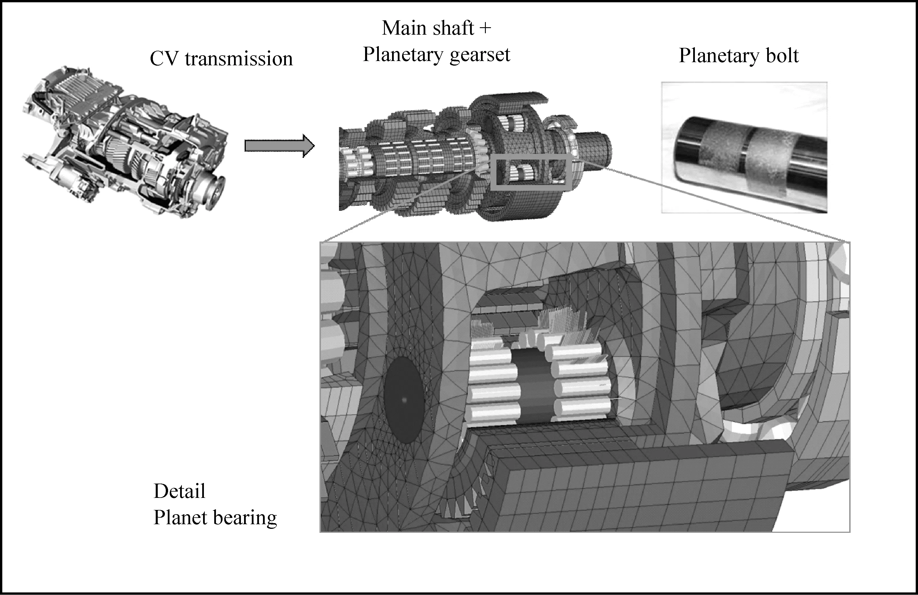
图5 计算流程与实例
这项研究的目的是在于确定考虑齿轮接触下的行星齿轮轴承寿命。在研究中(图5),我们选择了以下参数(图6):同轴度偏差S(行星轴中心线),轴承间隙L(行星轴承),接触轮廓误差P(行星轴承),轴偏移Tx(行星轴水平方向),轴偏移Ty(行星轴垂直方向)、轴座误差B(与行星架的安装)以及轴倾斜度N(行星轴径向)。
为了确定其中的主要影响因素,需要对2197个不同组合进行全因子分析。在DoE(试验设计)的帮助下,这个数字能够被缩减到36个。这意味着计算速度更快。在此例中,并未对齿轮作应力相关的计算,而是使用了简化的接触模型。整体模型中的齿轮采用的是粗化的网格划分。
The required corrections of flank direction of a gearing are also determined using our own evaluation program. The deformation of previously defined evaluation nodes in connection with the known contact surfaces and flank directions results in signed correction proposals. The gradient of the flank direction correction is determined over a load range, and the sensitivity of the observed tooth contact to load changes can be read off from the gradient of the correction curve.
图6 影响轴承寿命目标的因素图示
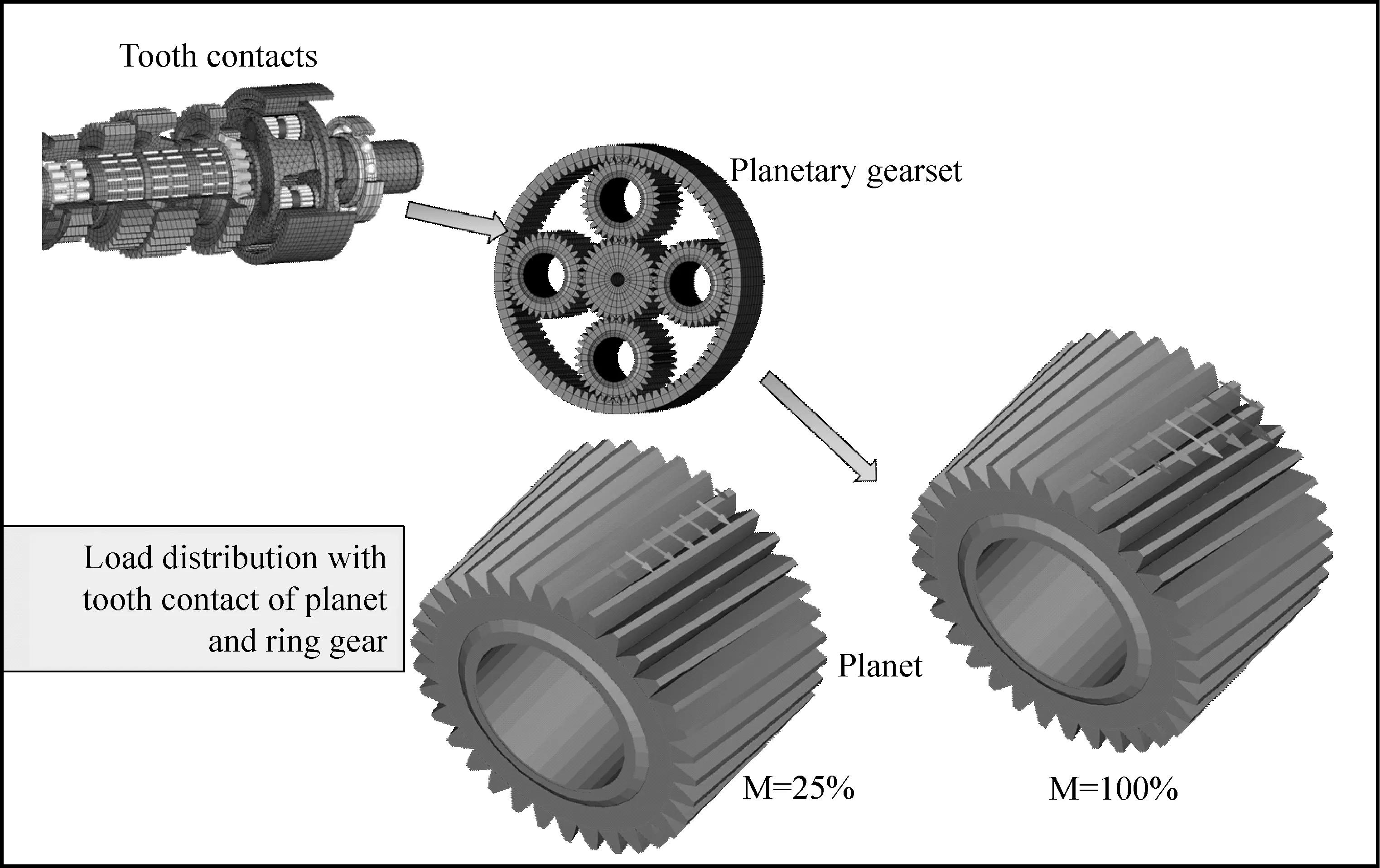
图7 负载相关的接触印痕变化
尽管进行了简化,接触的关键影响因素仍然计入了考虑范围。因此,针对太阳轮/行星轮和行星轮/齿圈的接触对,本例使用了点对点的接触定义,并对带鼓形量以及螺旋角修正(如果适用)的齿轮几何进行了仿真。
被测的螺旋角修正在小扭矩时传递的负载也较小。而增加到100%负载水平时,产生了偏向一端的接触印痕。这明确表明齿轮的接触印痕是和负载相关的,而且会不可避免地影响到轴承的接触印痕变化。在这个实例的研究中,考虑了齿轮和轴承的接触印痕相互作用。这意味着行星轮的周节误差影响也在考虑范围内。
对于行星轴承(图8),滚子轮廓是测量得到的,为了排除不稳定性对其形状进行了平滑处理。行星轴和轴承滚道是圆柱体,轴承间隙和滚子形状的组合形成了有限元模形中轴承的初始接触间隙。接触轮廓和轴承数据(滚子直径、滚子长度、滚子数量、内圈直径及位置参数)是采用采埃孚的前处理器来生成有限元网格。
轴承反作用力是从有限元结果中提取出来按照已知的鼓形比例转化到负载相关的压应力图表中。在给定的负载循环下,行星轴和行星轮与接触对象的相对滚动关系是不确定的。如果行星轴与行星架相固连,那么行星轴上损伤只发生于轴上滚道上的某一位置。 而当行星轮转动时,滚道会由转动负载所损伤。这时齿轮相关的损伤或总合性的损伤就要由我们采埃孚的轴承S/N曲线来判定。
For the bearing calculation, the compressive stresses that occur are determined from the contact forces and the known radii of curvature. Taking into account the location of damage and the stress reversal cycle, the maximum occurring damage in the axial and circumferential directions is determined. It is possible to effectively influence the contact compressive stress by modifying the contact gap on the outer or inner ring. Bearing damage is avoided or an increase in performance can be achieved without additional installation space. Apart from these optimization options of our own, we also use commercial FE optimization programs (e.g. gear body optimization, housing) to optimize rigidity and weight.
5 Applications
In the current application, we will demonstrate possibilities of the ZF programs presented by means of a roll-off simulation and a bearing calculation.
For a roll-off simulation (Fig.4), the shafts and surrounding rigidities up to the interface to the gearing are prepared. Using the ZF pre-processor
图8中标出的最大损伤是行星轮上的倾覆力矩造成的。来自于法向力、径向力和轴向力的部分倾覆力矩取决于行星轮和太阳轮及行星轮和齿圈啮合的接触印痕中心位置。在径向分布图中,可以看到滚子受接触印痕的影响。
The test points were re-calculated for an accelerated test procedure and carried out on the test bench. The test transmission bearings were evaluated in the back-to-back test setup. The new calculation and test results were also included in the DoE analysis.
为了分析主要影响因素,新提出的试验计划被用于验证计算结果。其他不受影响(滚子轮廓)或影响很小的(倾斜)的因素没有被考虑在内。为了加快试验过程,试验点被重新计算并运用在试验台架上。受测的变速器轴承在背靠背的试验设置中得到了验证。新的计算结果和试验数据也列于DoE分析中。
6 计算过程的输出结果及测试
量化地给出对轴承寿命的几何影响因素已经
for gearing, an FE meshing pattern is generated from internally provided manufacturing data for the gearing including corrections. The gearing model is integrated in a precise position in the overall model. Subsequently, the contact partners, loads and boundary conditions must be entered. The further calculation models are generated from this basic model by transforming the coordinates of the gearing nodes. In this case, 10 evenly distributed roll-off positions of a pitch module were evaluated. The result is the distribution of the load-sensitive contact and root stresses over the contact width. The example of a simple spur gear chain shows that the flank corrections for the selected load situation are well chosen. In order to correctly record the influences of housing and shaft deformations in connection with the flank corrections, the roll-off simulation is always carried out in the overall model and/or a reduced sub-model with corresponding shifting boundary conditions.
Recording the effects of pitch errors and tolerances on bearing behavior is more complex for planetary gearsets. This is shown in the following using the example of a planetary gear bearing.
The objective of the examination is to ascertain the service life in a planetary bearing taking into account the gearing contact. For the study (Fig.5), we selected the parameters (Fig.6) bolt misalignment S (of the bolt axis), bearing clearance L (of the planetary bearing), contact profile P (of the planetary bearing), bolt pitch Tx (of the planetary bolt in tangential direction), bolt pitch Ty (pitch of the planetary bolt in radial direction), bolt bearing B (fixing in planet carrier), and bolt inclination N (of the planetary bolt in radial direction).
实现。通过计算能够确定轴承工作寿命中的主要影响因素。计算能确定损伤的位置和发生几率。在加工公差范围内,选择不利的参数时,工作寿命下降可达37%。而在有利参数下,可以期望工作寿命增长达74%。以上结果是在正向载荷下得到的。在相同位置的反向载荷会造成行星轴另一边的损伤,但并不影响这些计算结果。
预测图表(图9)表现了各个参数的影响。使用垂直虚线,可以作出工作点位置。
预测数值如图9中y轴所示,x轴列出了各因素数值的范围。较大的斜率意味着影响也越大, 反之较小的斜率意味着影响也越小。但是,这些曲线只是简单的概括,当考虑交互作用时,斜率变化可能会非常明显,甚至由正值变负值。在预测图表中能清楚地看到相互作用的影响。行星轴位置和同轴度的实例表明行星轴位置的影响是和同轴度的影响相互作用的。在同轴度偏差较小时,轴的位置对寿命几乎没有影响。而同轴度偏差较大时,其影响要大的多。
To ascertain the influence of the main parameters, 2197 different variants would be necessary for a full-factorial analysis. With the help of the DoE (design of experiments), the number of necessary calculations can be reduced to 36. This means the calculations can be made much more quickly. In this case, the gearing is not tested in relation to stress, but a simplified contact model is used. The gearing was integrated into the model with coarse FE mesh.
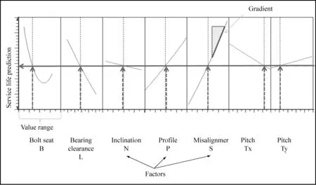
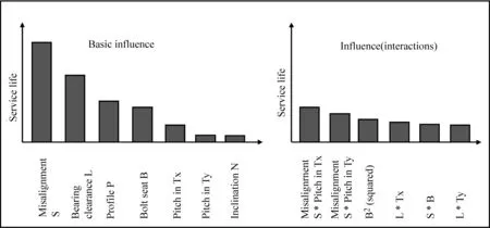
图9 使用DoE的结果分析
在帕累托图中,包括了单一及交互影响的分析。图中各影响变量以权重系数的形式表示。同轴度误差和轴承间隙对寿命的影响最大。而轴偏移和轴倾斜度的影响最小。
7 总结
通过系统地使用自有程序,可以进行更快速的有限元计算,所得结果也更有实际意义。使用我们的齿轮和轴承的网格划分程序,能够可靠地处理复杂几何体如齿轮和轴承。在各个不同应用领域,独立于模型尺寸的网格划分策略使有限元结构对运算结果的影响实现了最小化。运算结果也按标准流程进行了判定和解读。这显著提高了有实际意义的质量水平和可再现性。必要的文件流程使得初始数据文件和结果文件易于处理。标准化的流程也改进了结果的可再现性。
简化的实现使其他流程如DoE更加易于操作。对于大批量数据的规划、处理和评估也具有了可行性。同时,模型质量和所用流程通过运算结果质量得以验证。
可以对多种因素(如制造误差、微观几何和扭转刚度)进行系统地分析,以确定公差范围并避免不必要的生产成本。
可以对传动系统的稳定性进行确定,确认影响大的因素并按合适的方法进行处理。
可以确定最有效的方法来进行优化(如对现有安装间隙),以改进安全性和可靠性。
Even with this simplification, the decisive influences on the contact finding are still taken into account. For this, the gear geometry with crowning and if applicable with flank direction corrections is simulated using node-to-node contacts for the contact pairs sun/planet and planet/ring gear. The contact pattern (Fig.7) shows the distribution of the contact forces over the ring gear contact area at 25% and 100% sun torque.
The tested flank correction leads to lower load transfers at low torques. An increase to 100% load level produces a one-directional contact pattern. This makes it clear that load-dependent contact patterns in the gearing inevitably lead to contact pattern alterations in the bearing. The interactions between the gearing and bearing contact patterns are taken into account in this study. This means the influence due to errors in the planet pitch can also be considered.
For the planetary bearing (Fig.8), the roller profile was measured and the profile shape smoothed in order to rule out unsteadiness. The planetary bolt and the planetary raceway are cylindrical. The combination of bearing clearance and roller profile create the initial contact gap of the bearing in the FE model. The contact profile and the bearing data (rolling-body diameter, rolling-body length, number of rolling bodies, inner bearing diameters, and position data) are processed by the ZF pre-processor to generate an FE mesh.
The bearing reaction forces are extracted from the FE calculation results and converted with the known crowning ratios into a load-dependent compression diagram. Using a given load duty cycle, the overrolling relationships of the contact partners on the bolt and the planet are ascertained. If the bolt is fixed to the planet carrier, a constant location of damage on the bolt raceway results. If the planet turns, its raceway is damaged by a rotating load. Then gear-related or aggregate damage is determined using our own ZF bearing S/N curve.
The damage peak marked (Fig.8) is attributable to the tilting moments that occur on the planetary gear. The proportional tilting moments that result from the tangential, radial, and axial forces depend on where the main focus of a contact pattern is in the sun and ring gear meshing. In the diagram of the circumferential distribution, the rolling bodies involved in the contact pattern can be seen.
To verify the calculations, a new test plan was drawn up for the main influencing factors. Factors which were not to be influenced (roller body profile) or only had a slight effect (tilt) were not taken into account. The test points were re-calculated for an accelerated test procedure and carried out on the test bench. The test transmission bearings were evaluated in the back-to-back test setup. The new calculation and test results were also included in the DoE analysis.
6 Results from the calculation process and the test
The objective of quantitatively proving the geometric influencing factors on the bearing life was achieved. The main influencing factors on the service life can be determined by calculation. The calculation process can be used to determine both the location of damage and the damage probability. Within the boundaries of the manufacturing tolerances we were able to determine a reduction in service life by 37% when very unfavorable parameters were selected. Under favorable conditions, an increase in service life of 74% can be expected. The results were determined for the load direction traction operation. At superposition of coast loads, the load reversal damages the opposite side of the bolt and does not influence these results.
The predictive graph (Fig.9) shows the influences of the parameters. Work points can be set with the help of the perpendicular dotted lines.
The predicted values are shown on the y-axis in Fig.9. The x-axis gives the factors with their value range. A large rising gradient indicates a large influence, a small rising gradient
indicates a smaller influence. However, these curves are only snapshots -when interactions are taken into account, the curve gradients can change dramatically, including from positive to negative. An interactive effect can clearly be seen in the predictive graph. The example of the parameters bolt position and misalignment shows that the influence of the bolt position is dependent on the factor misalignment. In the lower value range of the misalignment, the bolt position barely has an influence on the service life, while at the other end of the scale, the influence is much greater.
In the Pareto chart, the single and the interactive effects are evaluated. The influencing variables are shown as weighting factors on the target figure. The misalignment and the bearing clearance have the greatest influence on the service life. The inclination and the bolt pitch are shown to have little influence.
7 Summary
Calculation according to FEM can be carried out more quickly and with much more meaningful results by systematically using our own programs. Complex geometries such as gearings and bearings can be reliably processed using our own FE mesh programs for gearings and bearings. With the multitude of application fields, size-independent mesh strategies minimize the influences of the FE structure on the results. The results are also determined and interpreted according to standardized processes. This also significantly improves the meaningful quality and reproducibility. The necessary documentation chain facilitates the documentation of the initial data and results. Standardized processes also improve the reproducibility of provisions and results.
The simplifications achieved also make the use of other procedures such as DoE easier. The planning, procedure, and evaluation of large data volumes is possible. Simultaneously, the model quality and the procedures used are tested in terms of quality of results.
The influence of various factors (e.g. manufacturing deviations, micro-geometry, surrounding rigidity) can be systematically evaluated. Tolerance values can be determined and unnecessary production costs avoided.
The robustness of transmission systems can be determined. Factors with a high impact can be identified and influenced using suitable measures.
The most effective measures can be determined for optimizations (e.g. for an existing installationspace). That improves safety and reliability.
[1] PERMAS-User’s Reference Manual, INTES Publication #450, Rev. F, Stuttgart 2000.
[2] Heinz Linke: Stirnradverzahnung; Berechnung-Werkstoffe-Fertigung, Carl Hanser Verlag 2010.
[3] G. Niemann, H. Winter: Maschinenelemente Band 2; Getriebe allgemein, Zahnradgetriebe-Grundlagen, Stirnradgetriebe.
征稿启事:
《传动技术》是由上海交通大学和德国ZF集团公司于1987年创刊合作创办的一本技术性刊物。杂志主要面向有关航空、汽车、船舶、冶金矿山、石油、化工、农机等从事传动设备研究设计制造方面中、高级工程技术人员和有关大专院校师生。
为增加杂志的信息量,拟推出《市场动态》栏目,介绍传动技术在上述领域中的发展趋势、行业动态、市场预测、新产品介绍、新技术应用等内容,其中新产品介绍、新技术应用等内容的文章希望短小精干、图文并茂。
Optimization of Gears and Bearings in Vehicle Transmissions by Means of FEMThomasMerath,JoachimNaas,Dr.FranzJoachim
ThomasMerath,JoachimNaas,Dr.FranzJoachimZF(China)InvestmentCo.,Ltd.
A large variety of gearings are developed and manufactured by the ZF Group. FEM is especially suitable for optimal, reliable gearing development. It can also easily be integrated into the ZF program landscape. This paper shows how the method can be used in the development process to optimize gearings. However, once again the strong interaction between gearing and bearing is repeatedly demonstrated. That is why ZF has also invested in the development of bearing calculations. We give an example of how rolling bearings can also be optimized for an ideal gearing contact pattern. Naturally, the methods can also be applied to running gears.
Transmission Gear Bearing FEM Optimization
1006-8244(2015)02-03-011
U463.212
A
