Compton散射对激光等离子体通道天线特性的影响
2015-03-23禹定臣郝东山
禹定臣, 郝东山
(1.黄淮学院信息工程学院, 驻马店 463000; 2.郑州工业应用技术学院信息工程学院, 新郑 451150)
Compton散射对激光等离子体通道天线特性的影响
禹定臣1, 郝东山2
(1.黄淮学院信息工程学院, 驻马店 463000; 2.郑州工业应用技术学院信息工程学院, 新郑 451150)
应用多光子非线性Compton散射模型和数值计算方法,研究了激光等离子体通道天线传播和辐射特性,结果表明:随通道周围介质损耗和传输模式阶数的增大,传输模式THnm衰减常数明显增大.这是因散射使通道内外电场和磁场增强,粒子间碰撞频率增大,电场使更多分子电离而吸收更多能量的缘故.随模式阶数增大,电性有耗介质使相移常数明显减小.这是因散射使高阶模式可能存在被耦合电场俘获的缘故.等离子体耦合频率为0.7附近,衰减常数随频率增大而剧烈增大.这是因散射使介质分子发生二、三阶电离,更多电子被耦合电场急剧加速的缘故.随天线长度增加,天线辐射方向图主瓣和副瓣数量、宽度和最大辐射方向发生明显变化.这是因散射使天线频率增大,辐射波长变短,粒子电离几率增大,辐射波能量和频率成分增大的缘故.
激光等离子体通道天线; 传输模式; 辐射特性; 耦合; 多光子非线性Compton散射
1 引 言
因大功率等离子体天线有重要应用,如大功率微波武器[1]、隐身技术[2]、核聚变快点火[3]等,故引起了人们的关注[4-7].Caillault等[8]设计出平面等离子体反射天线结构.Donald等[9]给出了该天线反射电磁波噪声产生机制.鉴福升等[10]指出,等离子体碰撞频率是影响反射波的主要因素.胡强林等[11]指出,圆和线极化行波辐射阻尼效应随等离子体密度增大而增大,高激光脉冲重复率频率可提高辐射阻尼效应[12].Petrova等[13]指出,注入不同条件激光可使通道寿命延长,不同线型脉冲对寿命影响较大[14].杨利霞等[15]提出新的电流密度拉普拉斯变换时域有限差分法计算等离子体球辐射.大多研究基于玻璃管封装惰性气体产生等离子体,使大功率等离子体天线增益受限[16,17].如何寻求大功率等离子体天线已成为亟待解决的重要课题.近期,夏新仁等[18]提出新概念激光等离子体通道天线构想.应指出的是,以上对等离子体通道天线研究均未考虑非线性Compton散射.文桦等[19]指出,等离子体内波强达1016W/cm2量级,非线性Compton散射开始显现.可见,Compton散射对等离子体天线辐射影响不可忽略.本文正是对该问题进行了研究.
2 天线设计及工作原理
等离子体通道天线的设计原理图如图1所示,其工作原理是:激光器发出的超强激光使空气电离且发生多光子非线性Compton散射,入射光和Compton散射光形成耦合等离子体通道,同步信号脉冲器的脉冲通过天线耦合到等离子体通道内,脉冲和通道以接近光速的速度同步向前传输,通过通道的侧面向外辐射电磁波.
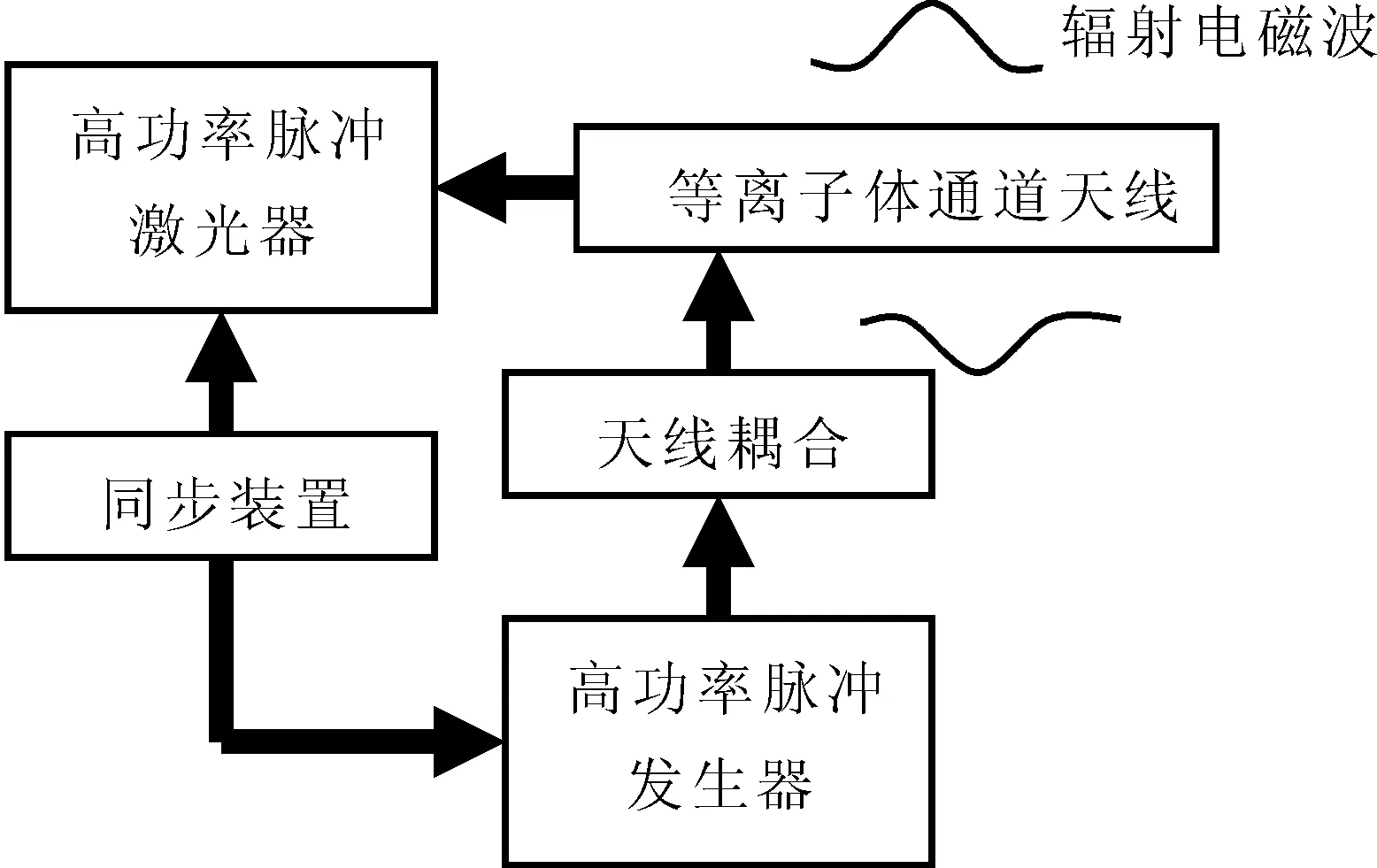
图1 等离子体通道天线示意图Fig.1 Sketch map of plasma channel antenna
3 天线传播特性
因由通道导行传输的电磁波始终滞后激光脉冲极短时间,且通道可近似为半径恒定、密度均匀的等离子体圆柱,故可将天线等效为周围充满有耗气体的无限长圆柱体,其模型如图2所示.
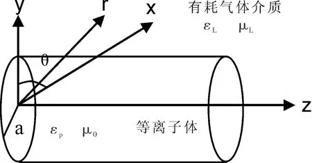
图2 等离子体通道天线电磁模型Fig.2 Electromagnetic model of plasma channel antenna
若等离子体中发生非线性Compton散射(简称散射),入射与散射光形成的耦合光频为[6]

(1)


(2)


(4)


(5)


(6)
通道内外耦合矢量位可分别表示为

exp(-jkz)+(Δωμ0εp+ωμ0Δεp+ωμ0εp)


exp(-jkz),r≤a
(7)

exp(-jkz)+j(ΔωμLεL+ωΔμL+ωμLΔεL)


exp(-jkz)+j(ΔωμLεL+ωΔμL+ωμLΔεL)

(8)

ΔxpJnBn+


(9)


(10)


(11)


(12)
其中xp=ppa,Δxp=Δppa;xL=pLa,ΔxL=ΔpLa.由式(9)~(12)非零解条件,可得

(ΔμrH+μrΔH)](J-εLpH)-(J-μtH)[ΔJ-

(13)

取通道周围有耗介质的电和磁性参数分别为Reεcr=5.5和μcr=1及Reμcr=5.5和εcr=1、ωcpe/ω=0.5、a/λ=6时,通道内THnm衰减和相移常数随介质损耗变化如图3~5所示.由图3~5知,衰减随通道周围介质损耗和传输模式阶数增大明显增大,同阶模式下,前者远大于后者.这是因散射使电和磁场增强,碰撞频率增大使更多电离分子吸收更多能量的缘故.同阶模式下,前者对相移影响大于后者,随模式阶数增大,相移常数明显减小.这是因散射使高阶模式被电场俘获的缘故.
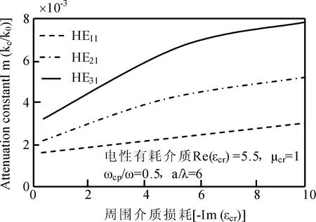
图3 电性有耗介质下传输模式衰减常数随介质损耗的变化Fig.3 Changes on attenuation constant of propagation model along dielectric loss under electric dielectric
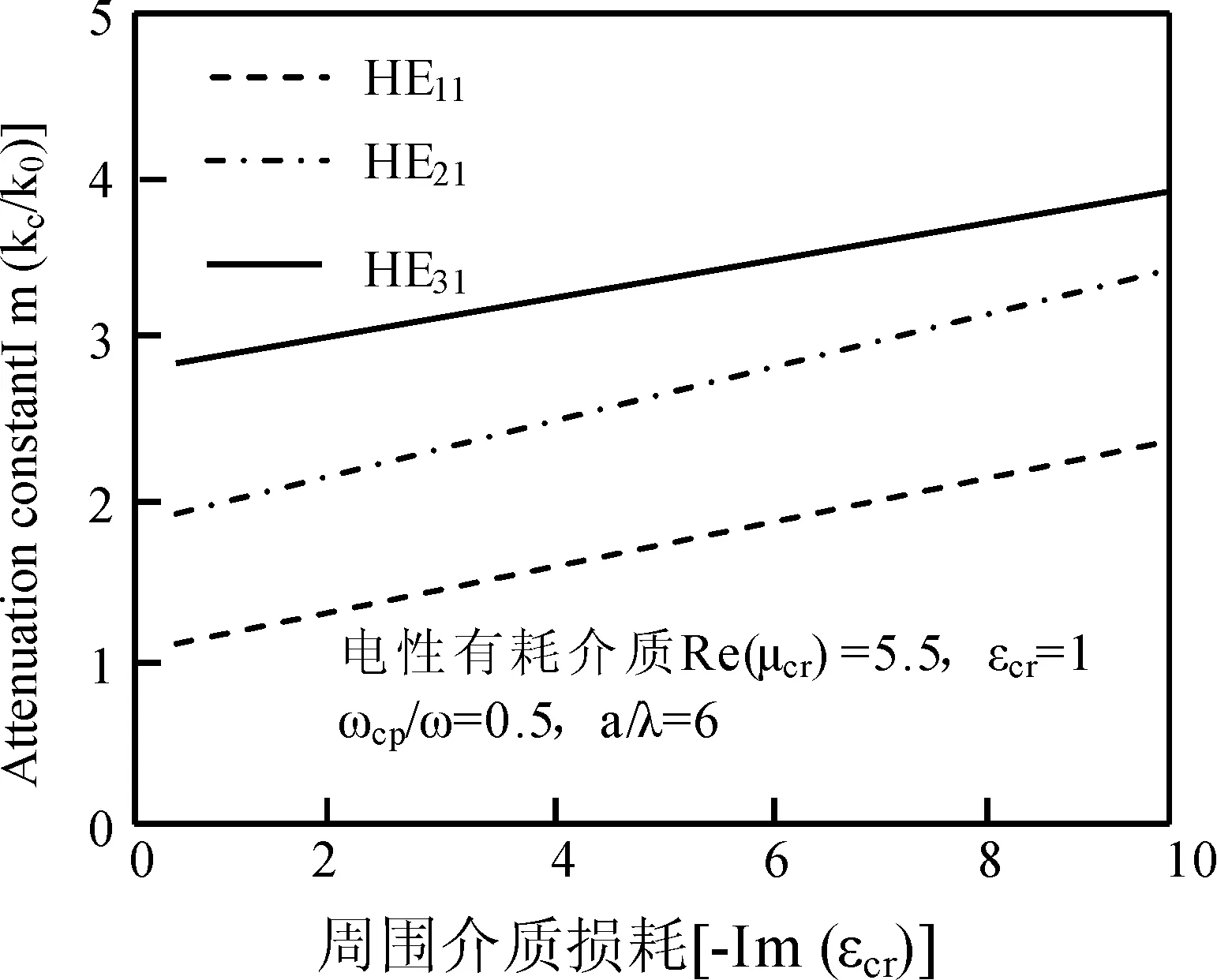
图4 磁性有耗介质下传输模式衰减常数随介质损耗的变化Fig.4 Changes on attenuation constant of propagation model along dielectric loss under magnetism dielectric
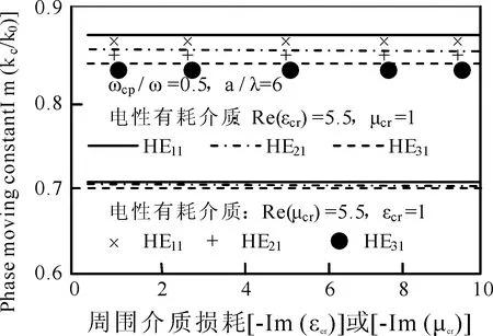
图5 传输模式相移常数随周围介质介质损耗的变化Fig.5 Changes on phase moving constant of propagation model along near dielectric loss
取等离子体通道周围的电性和磁性介质的参数分别为εcr=5.66(1-j)和μcr=1及μcr=5.66-5.66j和εcr=1、a/λ=6,THnm的衰减常数和相移常数随着ωcp/ω的变化分别如图6~8所示.由图6知,同阶模式的电性和磁性介质对相移常数的影响几乎是相等的,随着模式阶数的增大,该常数发生了微小的减小.这是因为散射使电子的辐射阻尼增强效应导致高阶模式吸收的能量减小,其被电场俘获效应消失的缘故.由图7和8知,ωcp/ω=0.7附近,衰减常数随着ωcp/ω的增大而剧烈地增大.这是因为散射使分子发生了二阶和三阶电离,有更多的电子被电场急剧加速的缘故.
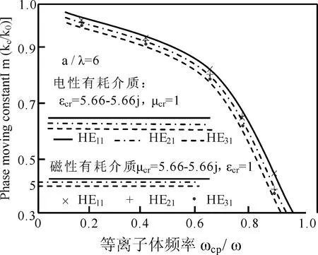
图6 传输模式相移常数随等离子体频率的变化Fig.6 Changes on phase moving constant of propagation model along plasma frequency
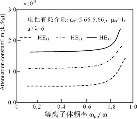
图7 通道周围为电性有耗气体介质时,传输模式衰减常数随等离子体频率的变化Fig.7 Changes on attenuation constant of propagation model along plasma frequency dielectric loss under electric dielectric near channel

图8 通道周围磁性为有耗气体介质,模式衰减常数随等离子体频率的变化Fig.8 Changes on model attenuation constant along plasma frequency under magnetism dielectric near channel
4 天线辐射特性
将激光等离子体通道天线等效为周围充满空气、密度均匀、半径和长度为a和L的如图9和10所示等离子体圆柱体,分别为从天线初始端耦合电磁波的单极式天线和从通道中间耦合电磁波的驻波对称振子式天线.
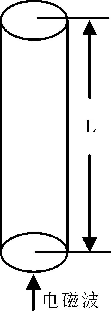
图9 单极式等离子体通道天线示意图Fig.9 Sketch map of channel antenna of single polar laser plasma
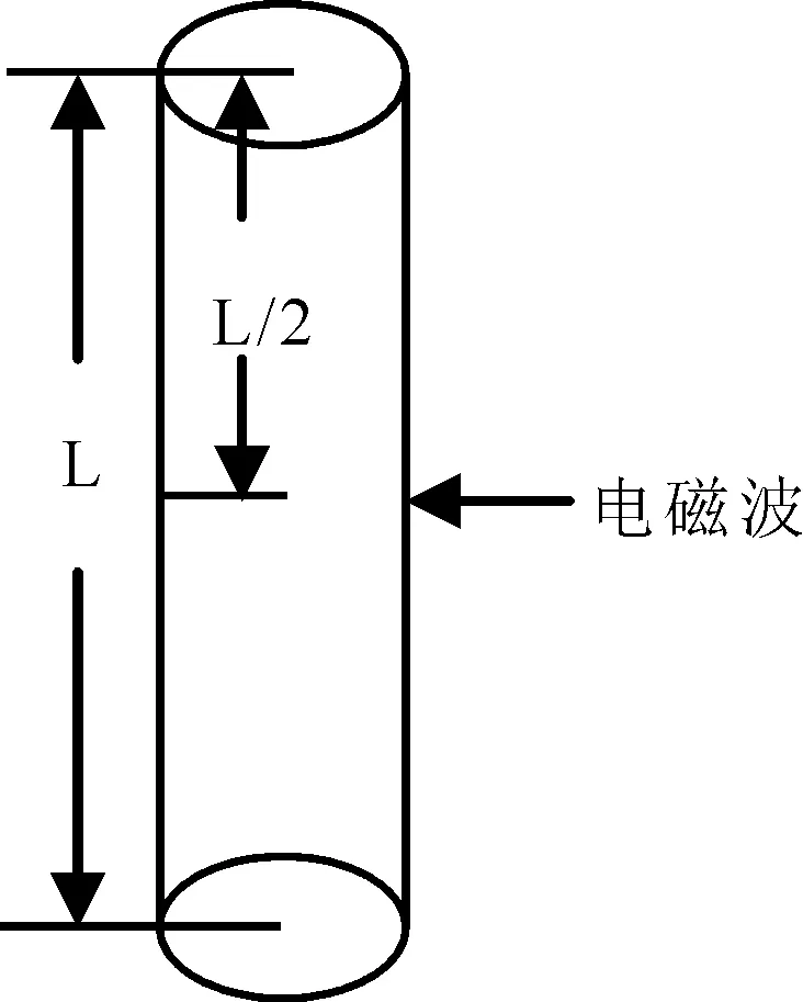
图10 驻波对称振子式等离子体通道天线示意图Fig.10 Sketch map of channel antenna of laser plasma of standing wave symmetry oscillation
图9天线,信号在通道表面以行波传输且与等离子体发生散射时,其表面耦合电流为
′)+ΔJx(Δz′)≈
J0exp[j(ωt-kz′)]+ΔJ0exp[j(ωt-kz′)]
(14)
式中,ω为信号频率;J0和ΔJ0分别为散射前的电流振幅及其扰动.对于较短的天线,辐射电场方向函数为

(15)
对图10天线,其表面耦合电流为


(16)
由式(15)和(16),可得

(17)
取εcr=μcr=1,结合辐射场对称性及其主模式为n=0的TM表面波,得TM波在天线周围空气中的纵和横向电磁场在圆柱坐标系中的关系为
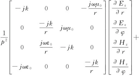
(18)
由式(18),可得横向电磁场切向分量及横向电磁场分别为

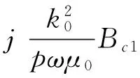
(19)
Ecφ=0
(20)
Ecpz=Ac1J0(ppr)exp(-jkz)+
Ac1ΔJ0(Δppr)exp(-jkz)
(21)
Hcpz=0
(22)
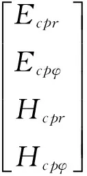
(23)
横向电磁场的切向分量为

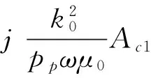
(24)
Ecpφ=0
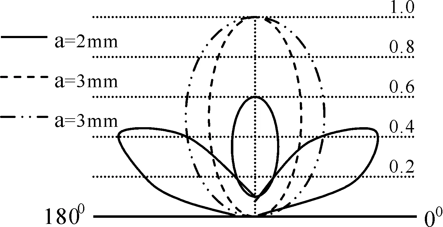
(25)
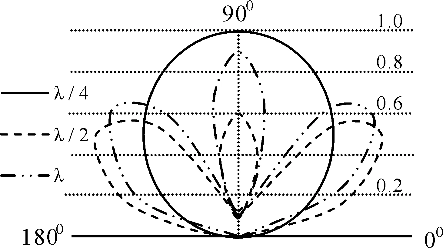
对单极天线取ωcp=31.4 GHz,νcp=4 GHz,a=2 mm,ω=500 MHz,L=λ/4、λ/2、λ时,E面辐射方向和f(φc)随φc=φ+Δφ变化如图10和11所示.由图10知,0 图11 单极式天线的fcΦ随Φ的变化Fig.11 Changes on f cΦ of single polar antenna 对于称振子式天线取图10和11中的参数,E面辐射方向随着天线长度的变化关系如图12所示.由图12知,当0 图12 对称振子式天线方向图随天线长度的变化Fig.12 Changes on direction map of symmetry oscillation along antenna length 图13 对称振子式天线方向图随等离子体密度的变化Fig.13 Changes on direction map of symmetry oscillation along plasma density 图14 对称振子式天线方向图随通道半径的变化Fig.14 Changes on direction map of symmetry oscillation along channel radius 本文基于多光子非线性Compton散射模型,分析了散射对天线特性的影响,得出如下结论: 1)与散射前相比,随通道周围介质损耗和模式阶数增大,模式衰减常数明显增大.电性有耗介质使较高阶模式相移常数明显减小.随同阶模式阶数增大,两介质对相移常数影响几乎相等. 2)等离子体耦合频率ωcp/ω=0.7附近, 衰减常数随耦合频率增大而急剧增大. 3)随单极式天线长度增加, 其辐射方向图主瓣宽明显减小, 最大辐射方向由180°向90°方向明显移动,主瓣和第一副瓣方向系数均明显增大.对称振子式天线长度0 4)随电子密度增大, 辐射方向主瓣由2瓣变为1瓣, 最大辐射方向由0°和180°方向转向90°方向, 主瓣明显变宽. 5)随等离子体通道半径增大, 辐射方向主瓣由2瓣变为1瓣, 最大辐射方向由0°和180°方向转向90°方向, 主瓣更宽. 对以上结论给出了初步物理解释.这些结论对于人们设计和控制等离子体通道天线传输特性应具有一定的参考价值. [1] Ginzburg N S, Korovin S D, Pegel I V,etal. Production of ultra-short high-power microwave pulses in Cerenkov backward-wave systems [J].LaserPhysics, 2006, 16(1): 79. [2] Chen L S, Ma H X. Applying in aerial stealthy on plasma technology [J].RadarScienceandTechnology, 2005, 3(3): 375(in Chinese)[ 陈林松, 马红星. 等离子体技术在天线隐身中的应用[J]. 雷达科学与技术, 2005, 3(3): 375 ] [3] Song Z X, He L M, Zhang J H,etal. 3D numerical simulation of supersonic plasma ignition process [J].HighPowerLaserandParticleBeams, 2013, 24(11):1746(in Chinese)[ 宋振兴, 何立明, 张建邦, 等. 超音速等离子体点火过程的三维数值模拟[J]. 强激光与粒子束, 2013, 24(11): 1746 ] [4] Feng G H, Hao D S. A new model on photonic band gap structure in high power laser PPCs under Compton scattering [J].JournalofAtomicandMolecularPhysics, 2012, 29(1): 91(in Chinese)[ 冯光辉, 郝东山. Compton散射下激光PPCs光子带隙结构新模型[J]. 原子与分子物理学报, 2012, 29(1): 91 ] [5] Liu J T, Hao D S. Influence of initial velocity of ion on iplasma sheath thickness under Compton scattering [J].JournalofAtomicandMolecularPhysics, 2014, 31(3): 443(in Chinese)[ 刘经天, 郝东山. Compton散射下离子初始速度对等离子体鞘层厚度的影响[J]. 原子与分子物理学报, 2014, 31(3): 443 ] [6] Liu A H, Hao X F, Hao D S. Influence of Compton scattering to propagation of oblique laser pulse in plasma [J].JournalofAtomicandMolecularPhysics, 2011, 28 (6): 102(in Chinese)[ 刘安辉, 郝晓飞, 郝东山. Compton散射对斜入射激光脉冲在等离子体中传输的影响[J]. 原子与分子物理学报, 2011, 28 (6): 102 ] [7] Yu D C, Hao X F, Hao D S. Gain clan of cross -phase modulation instability of plasma under Compton scattering [J].JournalofAtomicandMolecularPhysics, 2013, 30(1): 167(in Chinese)[ 禹定臣, 郝晓飞, 郝东山. Compton散射下等离子体交叉相位调制不稳定性增益谱[J]. 原子与分子物理学报, 2013, 30(1): 167 ] [8] Caillault L, Larigaldie S. Mechanisms of a linear hollow cathode used for the production of a helium plasma sheet [J].J.Phys. D:Appl.Phys., 2002, 35: 1010. [9] Donald P M, Richard F F, Robert E P,etal. Microwave emission from plasmas produced by magnetically confined electron beams [J].IEEETrans.PlasmaSci., 2002, 32 (2): 426. [10] Jian F S, Zeng H, Zou H Y. Simulation of plasma planar reflecting electromagnetic wave [J].ShipElectronicEngineering, 2011, 31 (4): 102(in Chinese)[ 鉴福升, 曾浩, 邹勇华. 等离子体平面反射电磁波的模拟仿真[J]. 舰船电子工程, 2011, 31(4): 102] [11] Hu Q L, Xiao G L, Yu X G. Radiation damping effects in ultra-intense laser-plasma interaction [J].HighPowerLaserandParticleBeams, 2013, 25 (6): 1379(in Chinese)[ 胡强林, 肖桂兰, 余晓光. 强激光-等离子体相互作用过程中的辐射阻尼效应[J]. 强激光与粒子束, 2013, 25 (6): 1379 ] [12] Chen J Z, Bai J N, Song G J,etal. Effects of laser shot frequency on plasma radiation characteristics [J].SpectroscopyandSpectralAnalysis, 2012, 32 (11): 2916(in Chinese)[ 陈金忠, 白津宁, 宋广聚, 等. 激光脉冲重复率对等离子体辐射特性的影响[J]. 光谱学与光谱分析, 2012, 32(11): 2916 ] [13] Petrova T B, Ladouceur H D, Baronavski A P. Numercial modeling of the electrical breakdown and discharge properties of laser-generated plasma channels [J].Phys.Rev. E, 2007, 76: 066. [14] Wang H T, Fan C Y, Shen H,etal. Temporal evolution of plasma density in femto-second light filaments [J].HighPowerLaserandParticleBeams, 2012, 24 (5): 1024(in Chinese)[ 王海涛, 范承玉, 沈红, 等. 飞秒光丝中等离子体密度时间演化特征[J]. 强激光与粒子束, 2012, 24(5): 1024 ] [15] Yang L X, Shen D H, Shi W D. Analyses of electromagnetic scattering characteristics for 3D time-varying plasma medium [J].ActaPhy.Sin., 2013, 62 (10): 104101(in Chinese)[ 杨利霞, 沈丹华, 施卫东. 三维时变等离子体目标的电磁散射特性研究[J]. 物理学报, 2013, 62(10): 104101 ] [16] Lu X.Researchonhighpowermicrowavepulseintheairbreakdown[C].6th International Symposium on Anten-nas, Propagation and EM Theory Proceedings, Beijing, 2003, 537. [17] Yang J H, Niu Z X, Zhou D F,etal.Thetemporaldispersecharacterinthenonlinearpropagationofhighpowermicrowave[C]. Asia-Pacific Radio Science Conference, Qingdao, 2004, 459. [18] Xia X R, Wang S J, Jin X L,etal. Theoretical study on new conception laser plasma channel antenna [J].JournalofCAEIT, 2011, 6(2): 147(in Chinese)[ 夏新仁, 王守杰, 金贤龙, 等. 新概念激光等离子体通道天线的研究[J]. 中国电子科学研究院学报, 2011, 6(2): 147 ] [19] Wen H, Hao X F, Hao D S. Influences of Compton scattering on transverse dispersion of relativistic electron-positron plasma [J].LaserandOptoelectronicsProgress, 2012, 49(8): 081902(in Chinese)[ 文桦, 郝晓飞, 郝东山. Compton散射下等离子体初温对质子产生的影响[J]. 激光与光电子学进展, 2012, 49(8): 081902 ] Influences of Compton scattering on the properties of laser plasma channel antenna YU Ding-Chen, HAO Dong-Shan ( 1. College of Information Engineering, Huanghuai University, Zhumadian 463000, China; 2. College of Information Engineering, Zhengzhou University of Industrial Technology, Xinzheng 451150, China ) By using the model of multi-photon nonlinear Compton scattering and the numerical computing means, the properties of the propagation and radiation of laser plasma channel antenna are studied. The results show that the attenuation constant of the propagation model THnmis clearly increased along the increases of the dielectric loss near the channel and the propagation model step number. The causes are that the electric field and magnetic field in and outside the channel are increased by Compton scattering, the collision frequency between the particle and particle is increased, and even more energies are absorbed by the even molecules ionized by Compton scattering. The phase moving constant is clearly decreased by the electric loss dielectric along the increasing model step number. This is dus to the possibility on the capture of the high step model by the coupling electric field. Near 0.7 coupling plasma frequency, the attenuation constant is acutely increased along the increasing frequency. The cause are that the 2nd and 3rd step ionizations of the medium molecule are taken by Compton scattering, and the even more electrons are sharply accelerated by the coupling electric field. The numbers of the main and vice piece, the widths and the maximum radiation directions in the map of the antenna radiation direction are clearly changed along the increasing antenna length. The cause are that because of the scattering,the antenna frequency is creased, the radiation wave length is decreased, the probability particle ionization is increased, and the energy and radiation wave frequency composition are increased. Laser plasma channel antenna; Propagation model; Radiation characteristic; Coupling; Multi-photon nonlinear Compton scattering 2014-09-04 河南省基础与前沿技术资助项目(092300410227) 禹定臣(1970—), 男,副教授,硕士,主要从事信号传输技术研究. 郝东山.E-mail: haodongshan@126.com 103969/j.issn.1000-0364.2015.10.016 TN011 A 1000-0364(2015)05-0815-08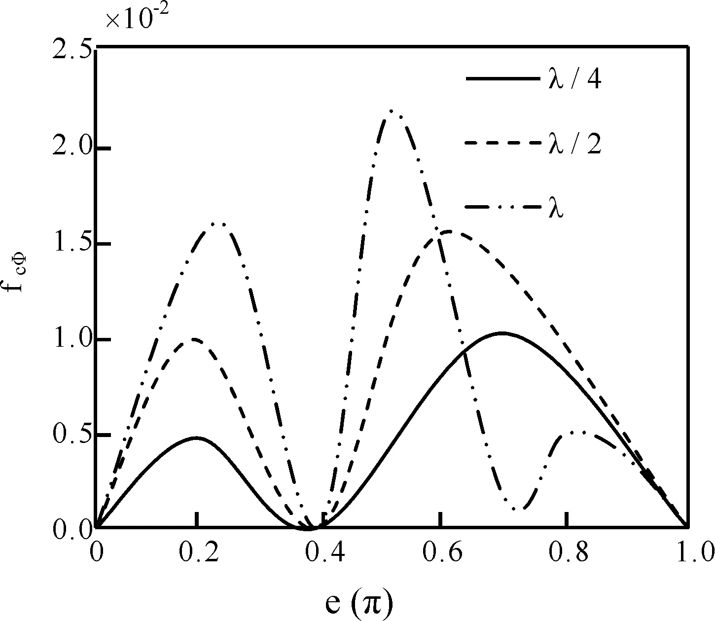
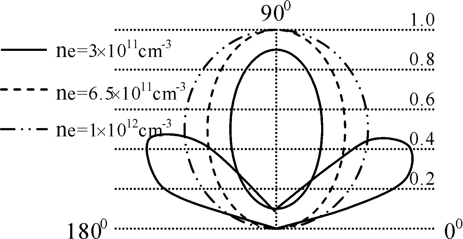
5 结 论
