Characteristics of friction welded AZ31B magnesium–commercial pure titanium dissimilar joints
2015-02-16KrthikSrinivsBVenktrmn
V.Krthik SrinivsB.Venktrmn
aDepartment of Mechanical Engineering,SSN College of Engineering,Kalavakkam 603 103,Tamil Nadu,India
bRadiological Safety and Environmental Group,Indira Gandhi Centre for Atomic Research,Kalpakkam 603 102,Tamil Nadu,India
Characteristics of friction welded AZ31B magnesium–commercial pure titanium dissimilar joints
A.K.Lakshminarayanana,*,R.Saranarayanana,V.Karthik Srinivasa,B.Venkatramanb
aDepartment of Mechanical Engineering,SSN College of Engineering,Kalavakkam 603 103,Tamil Nadu,India
bRadiological Safety and Environmental Group,Indira Gandhi Centre for Atomic Research,Kalpakkam 603 102,Tamil Nadu,India
It is essential to understand the weld interface characteristics and mechanical properties of dissimilar joints to improve its quality.This study is aimed at exploring the properties of friction welded magnesium–titanium dissimilar joint using tensile testing coupled with digital image correlation,optical and scanning electron microscopy,x-ray diffraction and microhardness measurements.Microstructurally different regions such as contact zone,dynamic recrystallized zone,thermo-mechanically affected zone,and partially deformed zone in the magnesium side were observed.No discernible regions were observed in the titanium side,as it had not undergone any significan plastic deformation.Phase analysis indicated that the aluminium from the magnesium side diffused toward the weld interface and formed a thin continuous intermetallic layer by reacting with thetitanium.Microhardnessmappingshowed a steep hardness gradient from the titanium to magnesium side.Criticalanalysisisdone on the tensile characteristics of the specimen and the response of the local regions to the deformation process is mapped.
Friction welding;Dissimilar joints;Microstructure;Digital image correlation
1.Introduction
Dissimilar combinations are widely gaining prominence as they cater to stringent industrial requirements[1].Dissimilar welded joints of titanium(Ti)and magnesium(Mg)alloy are an attractive combination for automotive applications(e.g. multi-material light weight vehicles).However,their significan difference in the physical properties,like melting point (Ti:1668°C,Mg:650°C),thermalconductivity (Mg: 156 Wm−1k−1,Ti:21.9 Wm−1k−1),lower mutual solubility, absence of reaction layer,unavailability of suitable fille materials makes joining them by fusion welding techniques difficul [2].Hence,an appropriate joining technique that overcomes the above mentioned problems is to be applied.A literature survey indicated that attempts were made to join this combination using techniques like diffusion bonding,laser beam welding, friction stir welding,friction welding and cold metal transfer welding[3–7].Tanabe and Watanab[3]investigated the effect of friction stir welding process parameters,namely rotational speed,tool pin profiland offset distance on the quality of dissimilar commercial pure titanium–AZ31 magnesium alloy joints and indicated that the fracture location was decided by the diffusion of aluminum from the magnesium side to the titanium side.Gao et al.[4]used laser keyhole welding to join Ti-6Al-4V grade titanium to AZ31B magnesium alloy and reported that the laser offset distance plays a major role in the weld quality,and further stated that the optimum laser offset distance should be in the range of 0.2–0.5 mm to get defect free joints.They also stated that titanium alloys with the presence of aluminum and vanadium increase the solubility of magnesium in titanium.Aonuma and Nakata[5]explored the possibility of joining ZK60 magnesium alloy with titanium and they observed that a thin Zn and Zr-rich layer formed at the interface,which had a significan effect on the tensile strength of the joint.Cao et al.[6]joined pure titanium and AZ31 magnesium alloy in a lap configuratio with the use of AZ61 fille wire by cold metal transfer welding and brazing.Although it was reported that sound welds can be obtained using this technique, the observed values of maximum tensile shear failure load were very low.To the best of the authors’knowledge,only one study100 kN displacement controlled servo hydraulic tensile testing machine.The CMOS camera(Marlin-F131)of DIC setup was focused on one side of the surface of the specimen which is coated with random speckle(black and white)pattern.The resolution of 1380×1035 pixels,frame rate of 10HZ,strain resolution of 50µε was used for the experiments.DIC systems were started from the beginning of loading capturing images at 50 Hz and 5 Hz frame rate.Images for performing image correlation were captured using a CMOS camera from which strain field were computed using associated DIC processing software (Vic2D).Vickers microhardness testing machine(Maker:was reported by Li et al.[7]on the friction heat production and atomic diffusion behavior during the friction welding of titanium–magnesium dissimilar joints.They reported that rotational speed and axial pressure play a major role in the generation of temperature and friction coefficient However,the microstructural and mechanical characteristics of friction welded magnesium-titanium dissimilar joints have not yet been reported.Hence,an attempt was made to understand the localized tensile characteristics of friction welded Mg-Ti dissimilar joints using digital image correlation and results obtained are correlated with microhardness distribution,microstructural features and phases present at the weld interface.

Table 1Chemical composition of base metal,Wt%(measured).

Fig.1.Dimensions of Specimens.
2.Experimental work
The chemical composition and mechanical properties of commercial pure titanium and AZ31B magnesium alloy are presented in Tables 1 and 2 respectively.Before welding,the workpiece was degreased with acetone solution to remove the oxide layer and the surface of the rods to be welded was milled to make the mating surface uniform.Rotary continuous drive friction welding machine(Maker:RV Machine tools,Coimbatore)was employed to fabricate the dissimilar Mg-Ti joints. From the trail runs carried out in our laboratory,the optimum process parameters were identifie and they are presented in Table 3.
An arrangement was made in such a way that magnesium rod rotate about its axis and titanium rod was kept stationary (Fig.1).The joints fabricated were cut along its cross-section by wire cutting electric discharge machine.The specimen was then polished with emery sheets of varying grit sizes.The polished specimen was etched with 4.2 g picric acid,10 mlacetic acid,10 ml water and 100 ml ethanol for duration of about 30 s.Optical microscope(Maker:Olympus,Japan)was utilized to capture the macrostructure and microstructure of the base metals and different regions of the dissimilar joint.Scanning electron microscopy(SEM)equipped with energy dispersive spectroscopy(EDS)was employed to determine the element distribution across the interface of the joint.

Table 2Mechanical properties of base metals(measured).

Table 3Welding conditions used.
Tensile specimens were prepared according to the ASTM E8M-09 standard.The fabricated joint,the specimen used for metallurgical characterization and the tensile test specimen are displayed in Fig.2.The tensile test specimen was loaded onto a
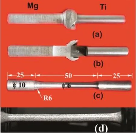
Fig.2.(a)Mg-Ti Joints,(b)Mg-Ti Joints(cross sectional view),(c)photographs of tensile specimens before testing(d)specimen prepared for DIC test.
3.2.MicrostructureShimadzu,Japan;Model HMV-T1)was employed with 0.05 kg load for measuring the hardness across the weld.The microhardness map was then constructed using the measured hardness values across the welded joint.Scanning electron microscopy(Maker:FEI Quanta HR-SEM)was applied to understand interfacial characteristics and to observe fracture morphology of failed tensile specimens.
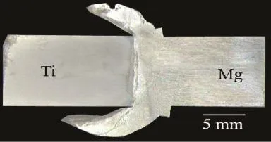
Fig.3.Macrostructure of friction welded Mg–Ti dissimilar joints.
3.Results and discussion
The factors that decide the joint integrity of dissimilar joints are the fl w stress and forging temperature of the base metal to be joined,elemental diffusion across the joint,formation of different phases,width of interlayer thickness and the changes in the grain morphology and its size.These factors can be correlated with the results presented in the following sections.
3.1.Macrostructure
The cross sectional macrostructure of friction welded dissimilar Mg-Ti joint is displayed in Fig.3.The flas formation on the magnesium side can be explained by comparing the forging temperatures and fl w stress of the magnesium alloy and the commercial pure titanium.The forging temperature of commercial pure titanium is around 815–900°C,whereas it is in the range of 290–345°C for theAZ31B magnesium alloy[8].
Fig.4 shows the effect of temperature on the yield stress of commercial pure titanium andAZ31B magnesium alloy[9,10]. Plastic deformation was initiated at the magnesium side due to its lower fl w stress when compared to commercial pure titanium.The excessive plastic deformation and the flas formation observed at the magnesium side are mainly due to the lower yield strength at high higher temperature and lower hot forging temperature as compared to commercial pure titanium.As the specimen was etched,an intermetallic layer at the weld interface and a dynamically recrystallized region at the magnesium side were also observed in the macrostructure.
Microstructure(Fig.5)shows different regions such as contact zone(CZ),dynamic recrystallized zone(DRX),thermo mechanically affected zone(TMAZ)and partially deformed zone(PDZ)at the magnesium side.No discernible regions were observed at the titanium side as it had not undergone any significan plastic deformation.
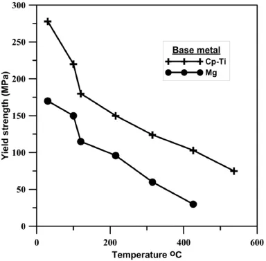
Fig.4.Yield strength comparison between commercial pure titanium and AZ31 magnesium alloy.
In the contact zone of magnesium side,titanium fragments were observed due to the mechanical metal transfer caused by the higher strain rate and severe plastic deformation on the rubbing surface.Very fin grains were also observed due to recrystallization.Dynamically recrystallized zone is observed next to contact zone.This zone does not undergo rubbing action and is formed due to heavy plastic deformation at higher temperature.This usually results in the formation of a large number of dislocations[11].The increase in dislocation density also increases the sub grain cell structure and leads to the formation of very fin dynamically recrystallized grains.In the thermomechanicallyaffectedzoneandpartiallydeformedzone, grainsarepulledsuchthattheyareorientedperpendiculartothe axis of rotation.This effect is higher in the thermomechanically affected zone as compared to the partially deformed zone due to its presence at the vicinity of weld interface and a higher strain rate.However,the grain orientation at the contact zone becomes parallel to the weld interface due to heavy deformation.Also, there is a significan variation in the grain size of magnesium from the contact zone to the unaffected base metal region as displayed in Fig.5.However,to understand the interface characteristics of Mg-Ti dissimilar friction weld,which is not clearly evidenced in the optical micrograph,scanning electron micrograph was used to analyze the weld interface and is presented in Fig.6.SEM analysis showed a thin,discontinuous intermetallic layer at the weld interface growing into the magnesium side of the joint.The average layer thickness of the intermetalliclayerappearstobelessthan15µmwithwavyweld interface.

Fig.5.Optical micrograph showing different regions of friction welded Mg-Ti joint.
3.3.Phase analysis
In dissimilar friction welding,high temperature solid state diffusion of various elements is the primary mechanism which improves the joint integrity due to the simultaneous application of rotation and applied forge pressure.Also,recent research results[12,13]have proved that the joint strength of dissimilar joints increased with the increase in the mutual solubility of elements present within the materials that are to be joined. SEM-EDS line scan was used to identify the elemental distribution across the friction welded magnesium–titanium dissimilar joint and it indicates that Al is concentrated at the weld interface,whereas titanium and magnesium changed gradually (Fig.7).
To identify the phases present,XRD analysis was carried out and the presence of TiAl3,Mg17Al12was confi med.It is well known from the Mg-Ti binary equilibrium diagram that[14]the maximum solubility of titanium in magnesium is about 0.12% and solubility of magnesium in titanium is zero and hence it is not possible to form a solid solution or an intermetallic between titanium and magnesium.However,titanium can react with aluminum present in the magnesium alloy and can form various intermetallic compounds like Ti3Al,TiAl and TiAl3.Due to the higher temperature and heavy deformation involved during friction welding,aluminum diffused toward the titanium interface since the mutual solubility between aluminum and titanium is higher when compared to magnesium and titanium,which resulted in the formation of Ti3Al intermetallic compound as is evident from the XRD results(Fig.8).
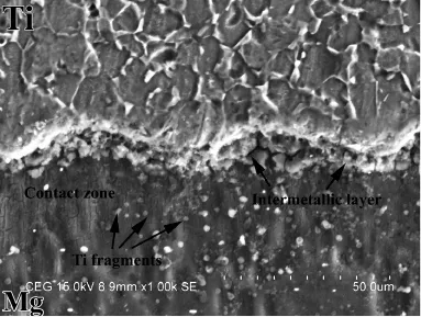
Fig.6.Scanning electron micrograph of Mg-Ti friction weld interface.
3.4.Microhardness map
The microhardness map shown in Fig.9 reveals that there is a steep gradient of hardness values from the titanium side to magnesium side.The interlayer,which formed between the magnesium and titanium,recorded a hardness value in the range of 100–130 HV.The hardness values are increased in the magnesium side for a distance of approximately 30µm from the weld interface.This is mainly due to the grain refine ment,precipitation of Mg17Al12,and Ti fragments in the magnesium side near the interface.However,no such change in hardness values was observed on titanium side due to the restricted deformation of titanium compared to the magnesium alloy during friction welding.
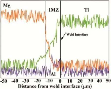
Fig.7.SEM–EDS line scan across the Mg-Ti friction weld interface.
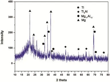
Fig.8.XRD pattern observed across the Mg-Ti friction weld.
3.5.Tensile properties evaluation using DIC
It is observed that the friction welded magnesium–titanium dissimilar joint failed at the magnesium side nearer to the interface and the tensile properties are comparable with the base magnesium alloy.Joint efficien y is found to be 104%, which is a ratio of tensile strength of welded joint to the tensile strength of lower strength base metal in case of dissimilar joint.However,the ductility of the joint is reduced by 50% compared to the base metal.The series of images depicted in Fig.10 shows the temporal strain evolution in the magnesiumtitanium friction weld.These images do not suggest a predominantly ductile behavior,or a pure brittle characteristic.The magnesium-titanium friction welded joint is characterized by a small elastic limit,the elastic strength being about 100 MPa. The unusual elongation characteristics of the alloy can be attributed to the difference in ductility and strength of the two materials.Titanium is a comparatively strong and ductile material (with about 30–40%elongation at room temperature),whereas magnesium is relatively less strong.The ductility of magnesium at room temperature is limited due to its hexagonal closepacked crystal structure that results in a limited number of active slip systems.
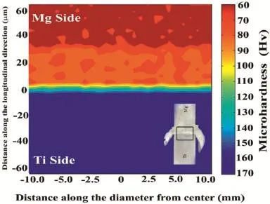
Fig.9.Microhardness map across the weld.
The strain evolution obtained through DIC showed that the strain localization was higher near the ends of gauge length during elastic and part of plastic region.This may be due to the stress concentration of fille given the specimen near the grip length.After sufficien plastic deformation in this region,strain localization changed to the vicinity of the weld interface where the fina fracture took place with higher strains.This small region,apparently being the weakest zone of the material,starts accumulating strain.Meanwhile,the titanium end of the material hardly deformed as the weaker magnesium shared the most of the applied load.This magnesium region,with time,gets strained even more,though the elongation is not drastic until 139.3 s.This reflect the brittle nature of the magnesium in the vicinity of weld interface.The specimen fails at 139.4 s after the start of application of load,and the difference in elongation between 139.3th and 148th second being about 6.25%indeed suggests that the tensile nature of titanium is being limited by the reduced strength and ductility of pure magnesium at room temperature.This non-uniform response of the Mg-Ti friction welded joint can hence be attributed to the steep property gradient between the materials constituting the joint.
3.6.Fracture morphology
Mg-Ti dissimilar friction welded joint failed at the vicinity of the intermetallic zone,which indicates that this is the weakest region.SEM fractograph of friction welded Mg-Ti dissimilar joint is displayed in Fig.11.The fractured surface showed a mixed mode of failure with the wavy nature of edges and some portions with fla deboning.This wavy nature with discontinuous crack growth resulted in a well-developed chevron pattern.This kind fracture is caused by initiations of multiple cracks by the presence of hard particles in a soft matrix.EDS analysis of fractured surface also confi med the presence of Ti particles which triggered the formation of multiple cracks.Since the chevron pattern of failure occurs with only plastic deformation,it is concluded that the failure of Mg-Ti friction weld is intermediate between brittle and ductile fracture.
4.Conclusions
An attempt was made to join AZ31B magnesium and commercially pure titanium by friction welding and the metallurgical and mechanical properties were evaluated.From this investigation,the following important conclusions were derived.
•Microstructure of friction welded magnesium–titanium friction weld indicates that grain refinemen has occurred due to the mechanical metal transfer caused by the higher strain rate and severe plastic deformation on the rubbing surface. Also,a thin discontinuous intermetallic layer of less than 15µm at the weld interface was formed,which had ultimately grown into the magnesium side of the joint.
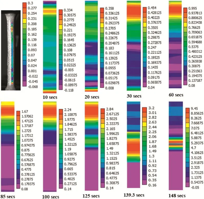
Fig.10.DIC strain map at various stages of tensile testing.
•EDS and XRD analysis confi med the presence of Al concentration andTi3Al intermetallics at the weld interface.This is also confi med by microhardness map constructed using Vickers microhardness measurements across the weld.
•The temporal strain evolution of the specimen obtained using digital image correlation suggests neither a predominantly tensile characteristic nor a pure brittle nature of magnesium–titanium joints.
•Mg-Ti friction welds failed in the magnesium side,in the vicinity of the intermetallic zone,which indicates that this was the weakest region of the Mg/Ti dissimilar friction welds.Chevron pattern of failure was observed,which is in agreement with the tensile test results.
Acknowledgement
The authors are grateful to Mr.N.Srinivasan,Research Fellow,Indira Gandhi Centre for Atomic Research(IGCAR), Kalpakkam,Tamil Nadu,India,for the help rendered to carryout digital image correlation experiments.

Fig.11.Fracture surface of Mg-Ti friction weld.
[1]Y.V.Budkin,Weld.Int.25(2011)523–525.
[2]M.Gao,Z.M.Wang,X.Y.Li,X.Y.Zeng,Metall.Mater.Trans.A 43A (2012)163–172.
[3]H.Tanabe,T.Watanab,Weld.Inter.22(2008)588–596.
[4]M.Gao,Z.M.Wang,X.Y.Li,X.Y.Zeng,Sci.Technol.Weld.Join. 16(2011)488–496.
[5]M.Aonuma,K.Nakata,Mater.Sci.Eng.B 177(2012)543–548.
[6]R.Cao,T.Wang,C.Wang,Z.Feng,Q.Lin,J.H.Chen,J Alloys Comp. 605(2014)12–20.
[7]R.Li,J.Li,J.Xiong,F.Zhang,K.Zhao,C.Ji,Trans.Non Ferrous Met. Soc.China 22(2012)2665–2671.
[8]G.E.Dieter,H.A.Kuhn,S.Lee,Handbook of Workability and Process Design,ASM International,Materials Park,2003.
[9]C.Leyens,M.Peters,Titanium and Titanium Alloys:Fundamentals and Applications,WILEY-VCH,Germany,2003.
[10]R.S.Busk,Handbook of Materials Selection,John Wiley&Sons,Inc., New York,2002.
[11]H.C.Dey,M.Ashfaq,A.K.Bhaduri,K.Prasad Rao,J.Mater.Process. Technol.209(2009)5862–5870.
[12]L.H.Shah,M.Ishak,Mater.Manuf.Process.29(2014)928–933.
[13]W.Shouzheng,L.Yajiang,W.Juan,L.Kun Mater.Manuf.Process. 29(2014)961–968.
[14]J.L.Murray,Bull.Alloy Phase Dia.,7(1986)245–248.
Received 2 February 2015;revised 16 November 2015;accepted 17 November 2015 Available online 7 December 2015
*Corresponding author.Department of Mechanical Engineering,SSN College of Engineering,Kalavakkam 603 103,Tamil Nadu,India.Tel.: +914427474844;fax:+914427474844.
E-mailaddress:lakshminarayananak@ssn.edu.in (A.K. Lakshminarayanan).
http://dx.doi.org/10.1016/j.jma.2015.11.004
2213-9567/©2015 Production and hosting by Elsevier B.V.on behalf of Chongqing University.
©2015 Production and hosting by Elsevier B.V.on behalf of Chongqing University.
杂志排行
Journal of Magnesium and Alloys的其它文章
- GUIDE FOR AUTHORS
- Influenc of rolling directions on microstructure,mechanical properties and anisotropy of Mg-5Li-1Al-0.5Y alloy
- Influenc of tool material and rotational speed on mechanical properties of friction stir welded AZ31B magnesium alloy
- Joining of AZ31 and AZ91 Mg alloys by friction stir welding
- Grain growth in calibre rolled Mg–3Al–1Zn alloy and its effect on hardness
- Anisotropy of the crystallographic orientation and corrosion performance of high-strength AZ80 Mg alloy
