Optimization of parabolic bars for maximum Bragg resonant reflection of long waves*
2015-02-16LIUHuanwen刘焕文SHIYunping石云萍CAODunqian曹敦虔
LIU Huan-wen (刘焕文), SHI Yun-ping (石云萍), CAO Dun-qian (曹敦虔)
School of Science, Guangxi University for Nationalities, Nanning 530006, China, E-mail: mengtian29@163.com
Optimization of parabolic bars for maximum Bragg resonant reflection of long waves*
LIU Huan-wen (刘焕文), SHI Yun-ping (石云萍), CAO Dun-qian (曹敦虔)
School of Science, Guangxi University for Nationalities, Nanning 530006, China, E-mail: mengtian29@163.com
(Received December 30, 2013, Revised August 12, 2014)
This paper presents an analytical solution for the problem of the long wave reflection by a series of artificial bars with parabolic configuration in terms of the associated Legendre functions. It is shown that both the reflection and transmission coefficients depend solely upon the number of bars, the dimensionless bar height, the dimensionless bar width and the dimensionless bar distance. Particularly, under the Bragg resonance condition, i.e., the distance between two adjacent bars is about half of the wavelength of the normal incident waves, the analytical solution for the peak Bragg resonant reflection is obtained, which reveals that the peak Bragg resonance depends upon the number of bars, the dimensionless bar height and the dimensionless bar width. Based on this solution, the optimization of the parabolic bars is made to obtain the maximum Bragg resonance and a group of optimal curves, which may be very useful in the design of Bragg breakwaters with parabolic bars.
Bragg breakwater, parabolic bar, maximum Bragg resonance, long wave reflection, optimal collocation curve
Introduction
When ocean surface waves propagate over periodic seabed topographies such as sinusoidal sandbars or ripples, the Bragg resonance occurs under the Bragg resonance condition, i.e., the distance between two adjacent sandbars or ripples is about half of the wavelength of the normal incident waves. The behavior of the Bragg resonance over natural periodic seabeds was studied extensively, as shown in Refs.[1-4].
Since the natural sinusoidal sandbars and ripples are not feasible in a coastal engineering technique, the concept of the Bragg breakwater was proposed, which consists of a series of submerged artificial bars with small size and low height located in the coastal region parallel to the coastline[5]. It is found that the Bragg breakwaters have a number of advantages over other types of breakwaters, for example, they have a minimal impact on local ecosystems as they are constructed under water, also they impose less burden on the supporting seabed and can be more naturally installed than a single massive breakwater on a weak seabed. Up to now, many Bragg breakwaters were built in coastal areas and a number of possible bar configurations were suggested and studied, such as rectangle, half-ellipse, rectified cosinoidal shape, triangle, trapezoid, semi-circular and parabolic shapes, as indicated in Refs.[5-10].
As its name indicates, the most important feature of the Bragg breakwater is the Bragg resonant reflection, which is the maximum reflection achieved under the Bragg resonance condition. However, it should be pointed out that this so-called maximum reflection refers to the bar distance only. If other topographical parameters such as the bar number, the bar width and the bar height are involved, this so-called maximum reflection is still not the maximum. This leaves a large space for us to conduct optimization for the bar dimensions to obtain the maximum value of the peak Bragg resonant reflection.
To the authors’ knowledge, the studies of the bar optimization to obtain the maximum peak Bragg resonance are few. In Ref.[11], based on the extended hyperbolic mild-slope equation, a numerical model was developed to investigate the Bragg resonant reflectiongenerated by multiple composite artificial bars. Their numerical examples indicate that the performance of the Bragg resonance for multiple composite artificial bars can be greatly improved by increasing both the bar height and the number of bars in different intervals. Based on the long-wave equation (LWE), Chang and Liou[12]studied the resonance by the Bragg breakwaters with trapezoidal bars and they found that the top plane width and the arrangement of the bars were two primary parameters in the design of multiple composite Bragg breakwaters. These findings are still more of qualitative nature than of quantitative nature.
To turn the aforementioned qualitative findings to quantitative ones, closed-form analytical solutions to describe the Bragg resonant reflection must be established. For a series of rectangular bars with piecewise constant water depths, the closed-form analytical solution to various wave equations is straightforward.
Based on the exact solutions to the LWE, Zeng et al.[13]conducted the optimization of rectangular bars to obtain the maximum Bragg resonant reflection. However, for a series of artificial bars with variable water depth, an analytical solution to any wave equation is not easy to obtain. Generally, the most often employed analytical solution is the simple formula developed by Miles[14], which is also shown in Refs.[12,15]. On one hand, Miles’ theory is a uniform method for an undulation bottom with arbitrary shape, on the other hand, Miles’ solution is restricted to seabeds with very small disturbances around the mean water depth, because of the application of the perturbation approximate technique.
It is noted that the Bragg breakwaters are often built in shallow water regions where most waves are long waves, so it is reasonable to employ the LWE as the governing equation to model the wave reflection by the coastal Bragg breakwaters. In Ref.[16], by constructing three exact solutions to the LWE for the wave reflection by the Bragg breakwaters with triangular bars, rectified cosinoidal bars and idealized trapezoidal bars, respectively, the optimizations are made for the three Bragg breakwaters to obtain the maximum Bragg resonant reflections.
In this paper, the Bragg breakwater with parabolic bars is studied. First, a closed-form exact solution to the LWE for the wave reflection by the parabolic Bragg breakwater is obtained, which is valid for any bar height. Then under the Bragg resonance condition, the aforementioned exact solution of the reflection coefficient degenerates into the exact solution for the peak Bragg resonant reflection coefficient. Finally, by analyzing the correlation between the Bragg resonance and the bar dimensions, a group of optimal curves associated with the bar number and the bar configurations are found, which can help us to conduct the optimization of bar dimensions for obtaining the maximum peak Bragg resonant reflection.
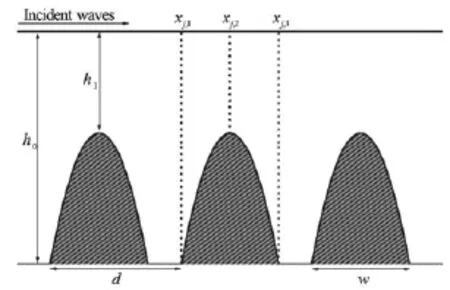
Fig.1 The wave reflection by a series of submerged parabolic bars
1. Long-wave reflection by parabolic bars
The linear long waves propagating over a series of submerged parabolic bars with an identical shape are considered, and these bars are parallel to the coastline and uniformly distributed on a horizontal bed, as shown in Fig.1 in a sketch of the problem. The water depth,h( x), in the interval [xj,1,xj,3],j=1,2,…,N, varies as follows

whereN is the number of bars,h0is the global water depth,h1is the submergence of the bars,His the dimensionless bar height with respect toh0, i.e.,H= 1-h1/h0,w is the bar width,xj,1=(j-1)d,xj,2= (j-1)d+w/2,xj,3=(j-1)d+w, and d=xj+1,2-xj,2is the distance between two adjacent bars.
According to the linear long-wave theory, the water surface elevation,η(x), satisfies the following LWE

wherew is the angular frequency of the waves and gis the gravitational acceleration.
If the incident waves come from the left, the water surface elevations in all subregions with constant water depthh0take the form


where k0=w/gh0is the wave number associated with the water depthh0, and all coefficients AR,AT,andare to be determined.
In the region within the front slope of thej-th bar:xj,1≤x≤xj,2, Eq.(2) becomes

By introducing the following notations

Equation (4) becomes

where the constant σ=k2w2/(16H)=π2W2/(4H)
0 with W=w/ Lbeing the dimensionless bar width with respect to the wavelengthLof the incident wave train.
Equation (6) is a non-symmetrical confluent Heun equation in its natural general form and all singular points of this equation are located at t=0, 1 and∞. Since the process to solve the confluent Heun equation is quite involved and tedious, as shown in Appedix A of Ref.[17], we further introduce the following notations:

then Eq.(6) becomes

Equation (8) is the associated Legendre differential equation of degree ν=-1/2and order µ=with singularities at τ=±1,∞, which has a general solution within the open interval (-1,1)as follows

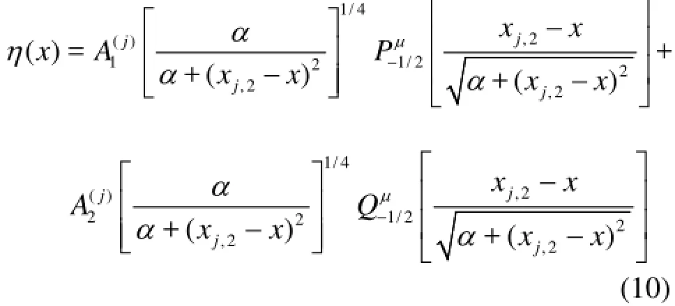
where α=(1-H) w2/(4H), andandare constants to be determined.
In the region within the back slope of thej-th bar,xj,2≤x≤xj,3, the wave elevation also satisfies the following equation

Similar to Eqs.(5) and (7), but with a slight difference, we introduce the following notations
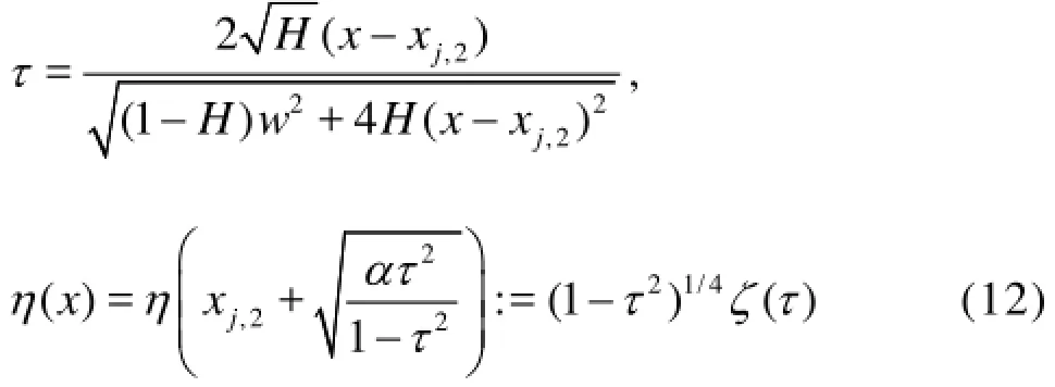
and we also obtain the associated Legendre differential Eq.(8). Finally, the water surface elevation in the region within the back slope of the j-th bar can be written as follows


The continuity of the wave elevations and the flow fluxes across the common boundaries requires

We now simplify Eq.(14) in the following manner.
At x=x1,1=0, we have

where

with

At x=xj,1,j=2,3,…,N, we have
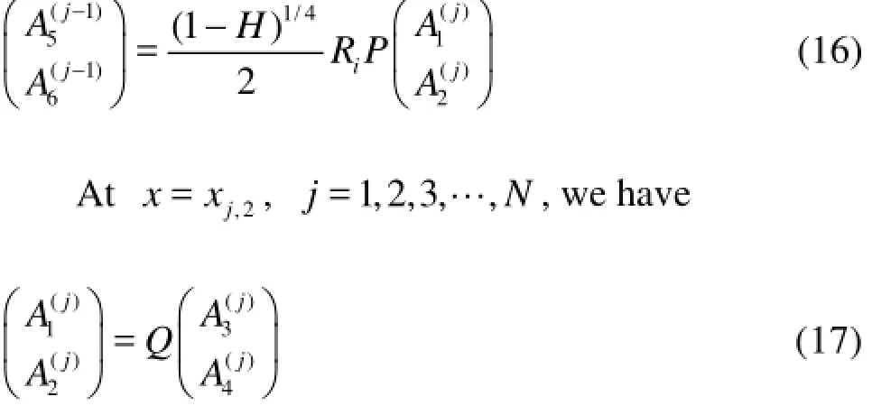
where


where D=d/ Lis the dimensionless distance between two adjacent bars.
Atx=xN,3, we have

Combining Eq.(15) and Eqs.(16)-(19), we have

where

The reflection coefficient KRover the Bragg breakwater withNparabolic bars is

Similar to the explanation for the wave reflection by a Bragg breakwater with trapezoidal barsbyChang[12]of our expression (20). It can be seen that the matrix B depends solely on the dimensionless bar height,H, and the dimensionless bar width,W, which means that it is the bar effect on the wave reflection and transmission so that it is called the bar transfer. The matrixS depends solely on the dimensionless space between two adjacent bars, i.e.,D- W, which means that it is the effect of the waves propagating over a and Liou, here we alsogive some physical analysisfinite horizontal region between two adjacent bars, so it is called the space transfer. It is clear that the reflection coefficient,KR, depends upon the four parameters:N,H,W andD.

Fig.2 Comparison between the present solution and Miles’theory for four different breakwaters with w =50 m, d =90 m,h0=4 m
2. Comparison with Miles’ theory
As is known, the governing equation based on the potential flow theory is the Laplace equation, which is very difficult to solve for the general variable water depth. By using the perturbation method with the dimensionless bottom disturbance around the mean water depth as the perturbation parameter, Miles[14]developed an approximate analytical solution to the Laplace equation for the waves reflected from an obstacle with a small and continuous height variation. For the case studied in this paper, the wave reflection coefficient obtained by the Miles’ theory is as follows

where kis the local wave number related to the water depth,h( x), and

which may be found in Refs.[12,15].
As a comparison between the present analytical solution and Miles’ theoretical solution, the reflection coefficients for waves reflected by four sets of parabolic Bragg breakwaters (N =2-5)with w =50 m, d =90 m,h0=4 mand H=0.025, 0.100, 0.175, 0.250 are calculated by using two methods and the computational results are shown in Figs.2(a)-2(d).
It is shown that for all four breakwaters with deep submergence, for exampleh1=3.9 m, the two solutions are almost identical. However, as the bar submergence decreases (i.e., the bar height increases), the discrepancy between the two solutions gradually becomes evident because the validity of the Milesʼ theory is restricted to a very small bar height,H, and the present solution is an exact solution to the LWE without any restriction with respect to the bar height.
3. Test the phenomenon of Bragg resonace
As mentioned before, the most important phenomenon associated with the Bragg breakwater is the Bragg resonant reflection. We now illustrate this phenomenon by using the present analytical solution (21). For h0=4 m,H =0.25and N =2-5, let (w, d) take three sets of values:(100 m,200 m),(100 m, 180 m)and (120 m,200 m). To guarantee that the waves we consider are in the long-wave range:0< k0h0<π/10, i.e.,0<(2π/L) h0<π/10, the wavelengthL of the incident waves must satisfy the condition:L >80 msince h0=4 m. Equivalently, this requiresthatL/(2d)>80/(2d)=0.222when d=180 m and L/(2d)>80/(2d)=0.2when d=200 m. By using the present analytical model, the reflection coefficients againstL/(2d )are calculated for L/(2d) varying from 0.25 to 2.5 and the related results for N=2-5are shown in Figs.3(a)-3(d). As expected, the peak Bragg resonant reflection coefficient occurs when the Bragg resonant condition is met, i.e., the incident wavelengthLis about twice that of the distanced between two adjacent bars, i.e.,D =1/2.
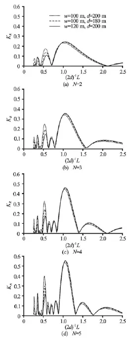
Fig.3 Bragg resonant reflection coefficient fors four sets of breakwaters with h0=4 mand H=0.25
4. Influence of bar dimensions on the Bragg resonance
According to the Bragg resonant principle, the peak Bragg resonant reflection coefficient,BR, occurs when D =1/2, i.e.,

This means that the peak Bragg resonant reflection coefficient,BR(N, H, W), depends solely upon the three bar parametersN,HandW. In this section we analyze the influence of these three parameters on BR(N, H, W).
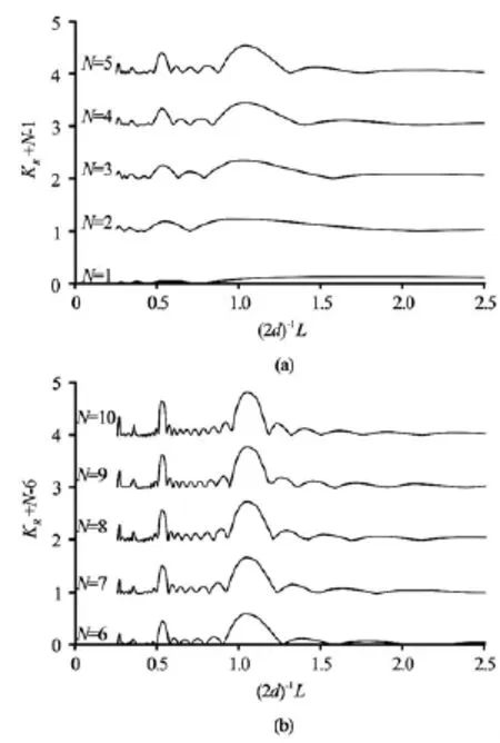
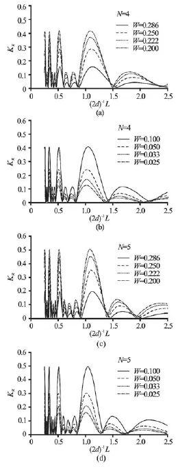
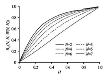
Fig.4 Influence of the number of bars,N, on the Bragg resonance whenh0=4 m,H =0.25,w =50 m,d= 100 m and 0.25 4.1 Influence of the number of bars Firstly, we use the present analytical model to investigate the influence of the number of bars,N , on the Bragg resonance. For fixed h0=4 m,H =0.25, w =50 mand d =100 m, let the number of bars,N, vary from 1 to 10, and let the incident wave length,L, vary from 0.5d to 5din which the peak Bragg resonance occurs atL≈200 mor W≈0.25. The computational results are plotted in Figs.4(a)-4(b). It can be seen that, asNincreases from 2 to 10, the peak Bragg resonant reflection coefficient BR(N,0.25, 0.25)increases from 0.23 to 0.83, and the crest of theBragg resonant reflection coefficient gradually changes from an asymmetrical shape into a nearly symmetrical shape. Fig.5 Influence of the dimensionless bar width,W, on Bragg resonance withh0=4 mand H=0.25 4.2 Influence of the bar width The most important factor of the Bragg breakwater is the Bragg resonant reflection, which is the maximum reflection achieved under the Bragg resonance condition D=0.5. However, it should be pointed out that this maximum reflection coefficient concerns the dimensionless bar distance only. If other topographical parameters such as the dimensionless bar width and the dimensionless bar height keep changing, as we will see in what follows, this so-called maximum reflectionBR(N, H, W)is still not the real maximum. This promotes us to conduct an optimization for all three bar dimensions. Fig.6 Influence of the dimensionless bar width,W , on Bragg resonance with h0=4 mand H=0.25 For a given number of bars,N, and a given dimensionless bar height,H, we now investigate the influence of the dimensionless bar width,W, on the peak Bragg resonance. For h0=4 m,H =0.25and N =2-5, we letWtake eight different values from 0.286 to 0.025. By using the present analytical model, the related reflection coefficients againstL/(2d)are calculated forL/(2d)varying from 0.25 to 2.5. The computational results are shown in Figs.5(a)-5(d) and Figs.6(a)-6(d), respectively. As can be seen, for the givenHand for each given number N=2-5, when the dimensionless bar width,W, decreases from 0.286 to 0.20, the peak Bragg resonant reflection coe-fficient increases, however, when the bar width,W, further decreases from 0.20 to 0.025, the peak Bragg resonant reflection coefficient turns to decrease. This means that whenW takes some value, the peak Bragg resonant reflection will achieve its maximum value. Evidently, this optimal choice is significant in the practical design and construction of Bragg breakwaters. Fig.7 Combined influences of N ,H and Won the peak Bragg resonant reflection coefficients 4.3 Combined influences of the number of bars, bar height and bar width In this subsection, we investigate the combined influences ofN,H andWon the peak Bragg resonance coefficient,BR(N, H, W). For each case of N=2, 4, 6 and 8, by using the present analytical solution, the peak Bragg resonant reflection coefficient, BR(N, H, W), versusW, changing from 0.0833 to 0.5, is calculated forHvarying from 0.4 to 0.9 and the corresponding results are plotted in Figs.7(a)-7(d). It is shown that, for a fixed number of bars,N, and a fixed small dimensionless bar width,W, such as W<0.1, when the dimensionless bar height,H, increases, the peak Bragg resonant reflection does increase accordingly. However, for a fixed bar number, N, and a fixed, but not small dimensionless bar width, W, when the dimensionless bar height,H, increases, the peak Bragg resonant reflection coefficient does not always keep increasing, and it goes down in some cases. This shows that the combined influences of the three parameters,N,HandW, on the peak Bragg resonant reflection coefficient,BR(N, H, W), is complicated. 4.4 Optimal collocation of parabolic bars In this section, the optimal collocation of parabolic bars for the maximum peak Bragg resonant reflection coefficient,BR(N, H, W), is determined. It is clear that, for any fixedN=N∗and H= H∗,B(N∗,H∗, W)is a univariate function ofW, R there exists a particular value ofWin the range0< W<0.5, say W=W∗, that corresponds to the maximum valueB(N∗,H∗, W∗). This particular value R W=W∗can easily be determined through numerical calculations and comparisons. As an illustration, in Figs.7(a)-7(d), all extreme value points(W∗,B(N∗, R H∗, W∗))for N∗=2,4,6,8and H∗=0.4,…,0.9are marked with “•”. For example, whenN =4and H=0.5, the peak Bragg resonant reflection coefficient achieves its maximum value 0.72453 atW= 0.21951, see Fig.7(b). Hence, for any fixed N=N∗, an optimal curve W=W( N∗,H)exists such that, for any given dimensionless bar height,H∗, the corresponding dimensionless bar width,W∗=W( N∗,H∗), in the optimal curve, W∗=W( N∗,H), corresponds to the maximum value BR(N∗,H∗, W∗). For N=N∗=2,3,…,7, all corresponding optimal curvesW∗=W( N∗,H)are plotted in Fig.8(a). These optimal curves provide an appropriate way to determine the parameters of the parabolic bars for a practical engineering design. For example, in order to construct five rows of parabolic bars parallel to a coast, i.e.,N=N∗=5. For the Bragg resonance, the dimensionless bar distance must be taken asD=0.5. By checking the optimal curveW=W(5,H)in Fig.8(a),we can find that, if the dimensionless bar height,H , is designed to be 0.4, i.e.,H=H∗=0.4, then to achieve the largest peak Bragg resonant reflection, the dimensionless bar width,W , should be 0.23077, i.e., W=W∗=0.23077, that is, the bar width should be w=W∗L=0.23077L. Fig.8(a) Optimal curves of W=W( N, H)for optimal collocation ofNparabolic bars with N=2,3,…,7 Fig.8(b) The peak Bragg reflection coefficients associated with the optimum bars for N=2,3,…,7 Besides, from Fig.8(a) it can be seen that, for any given number of bars, say N=Nˆ, the optimal functionW=W( Nˆ, H)is a decreasing function ofH, which means that, to obtain the maximum peak Bragg resonance, the lower the height of the bars is, the wider the width of the bars must be. It can be also seen in Fig.8(a) that, for any given dimensionless bar height, sayH=Hˆ, to obtain the maximum peak Bragg resonance, the smaller the number of the bars is, the wider the width of the bars must be. With the optimal curves available, the natural question is what are the peak Bragg reflections in optimum bars. To answer this question, engineers can decide the possible choices under a constraint of the minimum reflection since large reflection and low construction cost related to the height and the width of bars are the keys in engineering applications. By using the present analytical solution, the maximal peak Bragg reflection coefficients associated with the optimum bars are calculated and shown in Fig.8(b). The data in this figure show that, for N=2, the maximum peak Bragg resonanant reflectionBR(N, H, W( N, H))in optimum bars grows linearly with the dimensionless bar height,H, while for N≠2, the growth of the maximum peak Bragg resonanceBR(N, H, W( N, H)) in optimum bars is nonlinear. In addition, the maximum peak Bragg resonance in optimum bars increases with the increase of the number of bars, however, the margin effect of this increasing trend decreases as the number of bars increases. In this paper, an analytical solution in the closedform for the linear long-wave reflection by a Bragg breakwater with a number of submerged parabolic bars is obtained. It is shown that the reflection and transmission coefficients totally depend upon the number of bars,N , the dimensionless bar heightH, the dimensionless bar widthWand the dimensionless bar distanceD. It is further shown that the magnitude of the peak Bragg resonant reflection coefficient is a trivariate function BR(N, H, W), which implies that the peak Bragg resonance depends upon three bar parametersN,HandW. Based on the trivariate functionBR(N, H, W), a set of optimal curves for the optimal collocation ofN,HandWfor the Bragg breakwater with parabolic bars are established. As can be seen, these optimal curves can not only be conveniently used to analyze the phenomenon of the Bragg resonance but can also be easily used by engineers to conduct an optimal design of the parabolic Bragg breakwater. Acknowledgement This worked was supported by the State Key Laboratory for Coast and Coastal Engineering, Dalian University of Technology (Grant No. LP1303). [1] CHO Y.-S., LEE C. Resonant reflection of waves over sinusoidally varying topographies[J]. Journal of Coastal Research, 2000, 16(3): 870-876. [2] LIU H., YANG J. and LIN P. An analytic solution to the modified mild-slope equation for wave propagation over one-dimensional piecewise smooth topographies[J]. Wave Motion, 2012, 49(3): 445-460. [3] YU J., HOWARD L. N. Exact floquet theory for waves over arbitrary periodic topographies[J]. Journal of Fluid Mechanics, 2012, 712: 451-470. [4] YU J., ZHENG G. Exact solutions for wave propagation over a patch of large bottom corrugations[J]. Journal of Fluid Mechanics, 2012, 713: 362-375. [5] CHO Y.-S., YOON S. B. and LEE J.-T. et al. A concept of beach protection with submerged breakwaters[J]. Journal of Coastal Research, 2001, 34(Special Issue): 671-678. [6] HSU Tai-Wen, CHANG Hsien-Kuo and TSAI Li-Hung. Bragg reflection of waves by different shapes of artificial bars[J]. China Ocean Engineering, 2002, 16(1): 21-30. [7] CHO Y.-S., LEE J.-I. and KIM Y.-T. Experimental study of strong reflection of regular water waves over submerged breakwaters in tandem [J]. Ocean Engineering, 2004, 31(10): 1325-1335. [8] JEON C.-H. and CHO Y.-K. Bragg reflection of sinusoidal waves due to trapezoidal submerged breakwaters[J]. Ocean Engineering, 2006, 33(14-15): 2067-2082. [9] TSAI L.-H., HSU T.-W. and LEE C.-Y. Bragg reflection of water waves over tripe composites of rectangular bars[C]. Proceedings of the Twenty-first (2011) International Offshore and Polar Engineering Conference. Maui, Hawaii, USA, 2011, 896-902. [10] TSAI L.-H., KUO Y.-S. and LAN Y.-J. et al. Investigation of multiply composite artificial bars for Bragg scattering of water waves[J]. Coastal Engineering Journal, 2011, 53(4): 521-548. [11] HSU T.-W., TSAI L.-H. and HUANG Y. T. Bragg scattering of water waves by doubly composite artificial bars[J]. Coastal Engineering Journal, 2003, 45(2): 235-253. [12] CHANG H. K., LIOU J. C. Long wave reflection from submerged trapezoidal breakwaters[J]. Ocean Engineering, 2007, 34(1): 185-191. [13] ZENG Hui-dan, LIU Huan-wen and TANG Guo-ji. Optimal collocation to rectangular Bragg breakwaters for linear long-wave resonant reflection[C]. The Sixteenth Chinese Marine (Coastal) Engineering Conference. Dalian, China, 2013, 663-672(in Chinese). [14] MILES J. Oblique surface-wave diffraction by a cylindrical obstacle[J]. Dynamics of Atmospheres and Oceans, 1981, 6: 121-123. [15] WANG S.-K., HSU T.-W. and TSAI L.-H. et al. An application of Miles’ theory to Bragg scattering of water waves by doubly composite artificial bars[J]. Ocean Engineering, 2006, 33(3): 331-349. [16] LIU H., LUO H. and ZENG H. Optimal collocation of three kinds of Bragg breakwaters for Bragg resonant reflection by long waves[J]. Journal of Waterway, Port, Coastal and Ocean Engineering, 2015, 14(3): 04014039. [17] RENZI E., SAMMARCO P. Landslide tsunamis propagating around a conical island[J]. Journal of Fluid Mechanics, 2010, 650: 251-285. * Project supported by the Natural Science Foundation of China (Grant No. 51369008), the Natural Science Foundation of Guangxi (Grant No. 2014GXNSFAA118322), and the Innovation Project of Guangxi Graduate Education (Grant Nos. JGY2014052, YCSZ2013059, gxun-chx2013087). Biography: LIU Huan-wen (1963-), Male, Ph. D., Professor


5. Conclusion
杂志排行
水动力学研究与进展 B辑的其它文章
- Stability of a tumblehome hull under the dead ship condition*
- The impact of macroalgae on mean and turbulent flow fields*
- Numerical study of the performance of multistage Scaba 6SRGT impellers for the agitation of yield stress fluids in cylindrical tanks*
- Multi-scale Runge-Kutta_Galerkin method for solving one-dimensional KdV and Burgers equations*
- Ski jump trajectory with consideration of air resistance*
- United friction resistance in open channel flows*
