The effect of viscosity on the cavitation characteristics of high speed sleeve bearing*
2015-02-16WANGLili王丽丽LUChanghou路长厚
WANG Li-li (王丽丽), LU Chang-hou (路长厚)
1. College of Mechanical and Electronic Engineering, Shandong University of Science and Technology, Qingdao 266590, China, E-mail:wang-ly-ly@163.com
2. School of Mechanical Engineering, Shandong University, Jinan 250061, China
The effect of viscosity on the cavitation characteristics of high speed sleeve bearing*
WANG Li-li (王丽丽)1, LU Chang-hou (路长厚)2
1. College of Mechanical and Electronic Engineering, Shandong University of Science and Technology, Qingdao 266590, China, E-mail:wang-ly-ly@163.com
2. School of Mechanical Engineering, Shandong University, Jinan 250061, China
(Received December 30, 2013, Revised May 21, 2014)
The effect of viscosity on the cavitation characteristics of a high speed sleeve bearing is investigated theoretically and experimentally. The cavitation characteristics, the cavitation shape and the cavitation location of a spiral oil wedge hydrodynamic bearing are investigated experimentally by using the transparent bearing and the high-speed camera. The generalized Reynolds equation is established with considerations of the cavitation mechanism based on the modified Elrod method in theory, and the cavitations of different viscosity sleeve bearings are analyzed and compared. It is shown that the cavitations are strip-shaped for both the high viscosity lubricant and the low viscosity lubricant, and in the rupture region of the oil film at a high speed, the oil vapour or bubbles are produced. With the decrease of the supply pressure and the increase of the rotating speed, the rupture area of the oil film increases distinctly. The cavitation area decreases distinctly and the quality of lubrication is better for the low viscosity lubricant than for the high viscosity lubricant. The experiment results in general are consistent with the theoretical results.
spiral oil wedge, lubricating medium, viscosity, cavitation characteristic
Introduction
The hybrid journal bearing is widely applied in high speed spindle systems, due to its excellent keeping, high load capacity, and stability. High temperature heating restricts the increase of the rotating speed for the hybrid bearing. Currently, most hybrid bearings use high viscosity lubricant as the lubricating medium. With the increase of the rotating speed, the internal friction increases and the temperature of the oil film increases, which might even make the bearing burnt and the journal sticking. The use of low viscosity lubrication is an effective way to improve the rotating speed of the hydrodynamic bearing. With high speed, heavy load, and other more complex conditions, the loss caused by cavitation increases, which makes the oil film rupture an urgent research topics.
Riedel et al.[1]studied the influence of the design parameters and the variation of the additional supply flow rate through the feed hole related to the cavitation in the bearing. Wu et al.[2,3]solved the general Reynolds equation with mass conservation over the whole lubrication domain using an operator-splitting method. Braun et al.[4]discovered that the pressure in the cavitation region of the submerged journal bearing varies with the circumferential and axial locations. Fang[5]obtained clear photos of the whole-oil-film cavitation using high-speed CCD panoramic camera, and ideal photos of the cavitation distribution in the whole-oil-film by the method of coordinate transform. Li et al.[6]computed the cavitation region and the pressure distribution using the Fluent and the cavitation algorithm based on the JFO boundary condition (namely the mass conserving boundary condition), and the numerical results of this algorithm were compared with experimental data of previous researchers. Su et al.[7]and Li et al.[8]derived the generalized equation that describes the lubrication in the full film region and in the cavitation region by modifying the Elrod algorithm. Based on the Rayleigh-Plesset (PRE) model, Meng and Long[9]studied the film temperature of asliding bearing with consideration of the cavitation by using the computational fluid dynamics method. Shyu et al.[10]resolved the temperature and pressure distributions according to the thermohydrodynamic effects using the Legendre collocation method, the bulk-flow model and the Elrod’s cavitation algorithm. Hatakenaka and Tanaka[11]obtained convergent solutions of the temperature distribution with consideration of the reverse flow at the oil film inlet, and proposed a new method to calculate the heat flow at the pad-film interface in the cavitated region. Bayada and Meurisse[12]showed the impact of the cavitation model on the analysis of slip/no-slip hydrodynamic contacts. Oujja[13]applied a new numerical method to simulate the cavitation phenomenon in some general devices, and presented numerical applications in an elastic journal bearing to show the good performance of the method. Based on the modified Elrod cavitation algorithm, Wang et al.[14,15]computed the dynamically loaded journal bearings lubricated with micropolar fluids. Li et al.[16]presented a new gaseous cavitation model based on air solubility in the lubricant and it is shown that this new model is compatible with the JFO condition. Geller[17]analyzed the bearing characteristics using the FSI approach and a multi–phase model with integrated cavitation.
The applications for low viscosity sleeve bearings are few, and the studies of the effect of the viscosity on the cavitation characteristics are fewer. In this paper, the spiral oil wedge sleeve bearing (Fig.1) is studied, with three arc oil grooves tilted on the whole circumference and with oil return holes and oil feed holes at both ends of each groove. The unique structure of this new bearing makes its cavitation properties different from conventional bearings. The cavitation shape, the cavitation location, and the cavitation area of the spiral oil wedge hydrodynamic bearing are studied for both the high viscosity lubricant and the low viscosity lubricant theoretically and experimentally, to reveal the lubrication mechanism of the high speed sleeve bearing and to provide a theoretical and experimental foundation for a better understanding of the oil film distribution mechanism and the oil film boundary conditions.
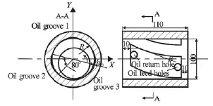
Fig.1 Schematic diagram of spiral oil wedge sleeve bearing
1. Experimental principles and equipment
The experimental equipment of the high speed spiral oil wedge sleeve bearing is designed by the authors. The experimental bearing is made of transparent glass, the journal is made of metal material and the region of cavitation can be observed using high-speed camera. In experiment, the rotating speed of the journal is adjusted by a frequency transformer; the input pressure is controlled by a relief value. In Fig.1, three oil grooves of the spiral oil wedge sleeve bearing are named oil groove 1, oil groove 2 and oil groove 3 to help describing the oil film rupture related with three oil wedges, with arrows denoting the rotation direction of the axis, which is downwards along the paper in the following cavitation pictures. The primary parameters of the bearing are given as follows: the journal diameter is 0.100031 m, the bearing clearancec is 0.000035 m, the bearing width is 0.11 m, the depth of the arc recess h0is 0.00012 m, the spiral angleβis 30o, the oil recess width is 0.09 m, and the wrap angle of the oil recess is80o.
2. Mathematical model
The mass conserving boundary condition (the JFO boundary condition) concerns the mass conservation in the oil film rupture and reformation location. Based on the assumption of the JFO boundary condition that the pressure gradient is zero in the cavitation region, the cavitation algorithm contains a switch function to modify the Reynolds equation in the cavitation location, similar to the Elrod algorithm[10,14].

where βtis the lubricant bulk modulus,pis the oil film pressure,g is the unit step function,
g =1Full film region,
g =0Cavitation region
A dimensionless density is defined as[10,14]

where ρcavis the density of the lubricant at the cavitation region,αρis the ratio of the lubricant density to the cavitation density, andρis the lubricant density.
Integrating Eq.(1) gives the expression of the pressure

Equation (3) can be simplified as

The unit step function dominates the fluid flow of different regions, including the full film region and the cavitation region, and the conservation of mass is satisfied. In the full film region, the fluid flow can be expressed by using the convection diffusion equation. In the cavitation region, the fluid flow can be expressed by using the convection equation. With pp= βt( αρ-1),αρ=pp/βt+1, and substituting Eq.(2) and Eq.(4) into the Reynolds equation for the density, the dimensionless generalized Reynolds equation can be expressed as

where p is the dimensionless oil film pressure,is the dimensionless oil film thickness,is the dimensionless axial coordinates,is the dimensionless circumference coordinates,βtis the dimensionless lubricant bulk modulus,Xiis the ratio of the bearing width to the diameter,Lis the width of the bearing.
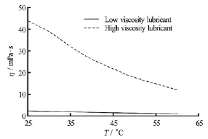
Fig.2 Comparison of oil viscosity
3. Comparison of oil viscosity
Two viscosity lubricants are used in the experiment. Figure 2 shows the distribution of the viscosity against the temperature. It can be seen from Fig.2: the viscosity of the low viscosity lubricant is about 94.62 percent lower than the viscosity of the high viscosity lubricant. With the decrease of the viscosity of the low viscosity lubricant, the internal friction decreases, and the lubricating oil flows rapidly. So the cavitation area decreases and the quality of the lubrication is improved for the low viscosity lubricant as compared with the high viscosity lubricant. Compare with the high viscosity lubricant, the study of the cavitation characteristics for the low viscosity lubricant will provide some practical reference for the application of the low viscosity lubricant.
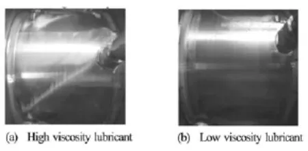
Fig.3 Cavitation shape of oil wedge 1 at N =2800 r/min, pin=0.1MPa
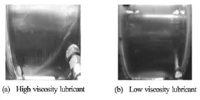
Fig.4 Cavitation shape of oil wedge 2 at N =2800 r/min, pin=0.1MPa
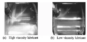
Fig.5 Cavitation shape of oil wedge 3 at N =2800 r/min, pin=0.1MPa
4. Experimental results and analyses
4.1 Cavitation shapes
Figures 3 through 5 show the cavitation shapes of the three oil wedges, Table 1 gives a comparison of the cavitation characteristics for both the high viscosity and low viscosity lubricants. The cavitations are strip-shaped for both the high viscosity lubricant andthe low viscosity lubricant, and the cavitation leading end forms a closed angle, which is consistent with the observations of Cole and Hughes[18]. The cavitation area decreases and the quality of lubrication is improved for the low viscosity lubricant as compared with the high viscosity lubricant.
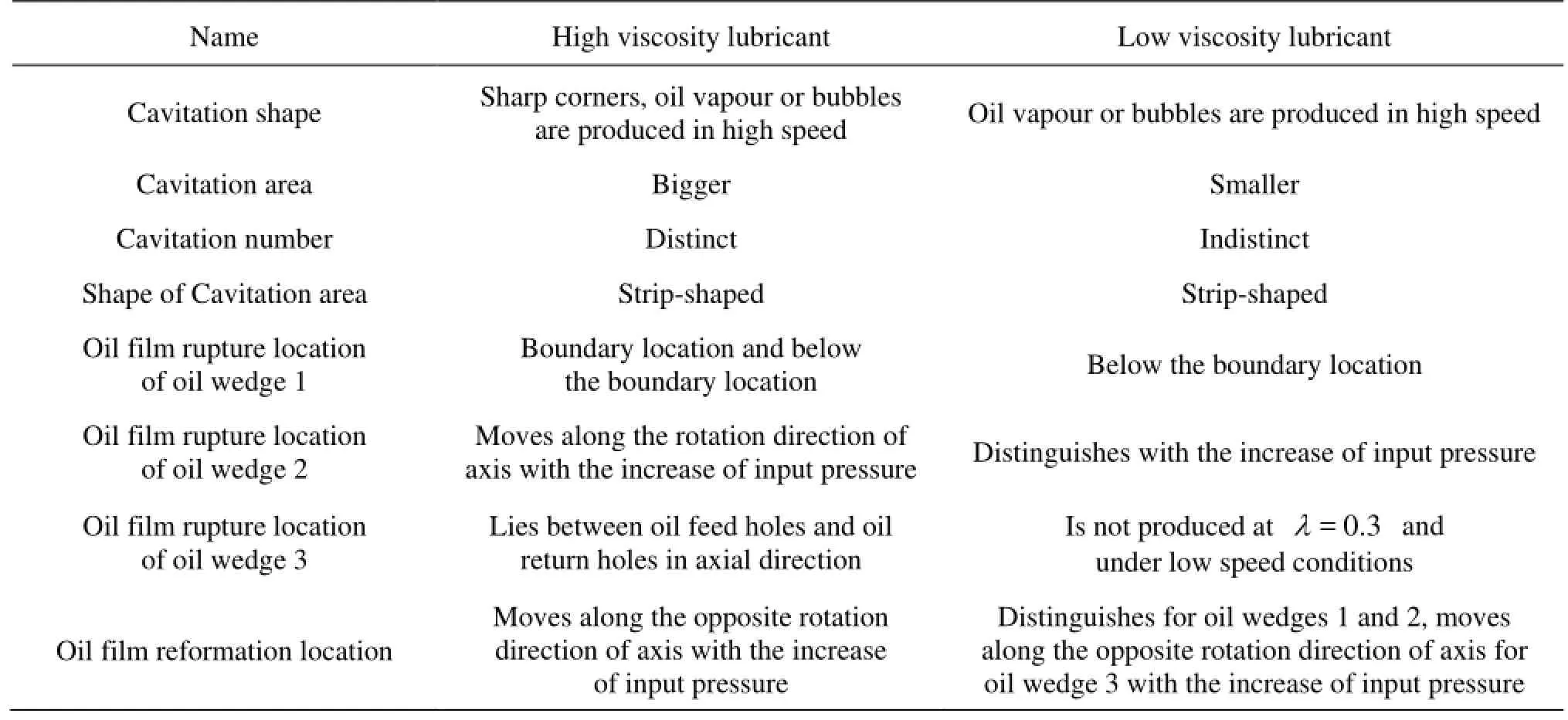
Table1 Comparison of cavitation characteristics for high viscosity and low viscosity lubricants
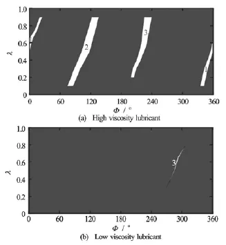
Fig.6 Oil film ruptures in experiment at N =1800 r/min, pin=0.3MPa
4.2 Experimental comparison of oil film ruptures
Figures 6 through 8 show the graphical comparison of experimental results for the oil film ruptures for different viscosities, in which the white areas are the cavitaion region, and the black areas are the oil film full region. It can be seen from Fig.6 and Fig.7 that with the increase of the rotating speed, for the high viscosity lubricant, the oil film rupture occurs at the three oil grooves, the oil film rupture shape changes little, and the oil film reformation location moves indistinctly along the rotation direction of the axis. But for the low viscosity lubricant, the oil film rupture occurs distinctly only at the oil groove 3, the cavitation area decreases compared with the high viscosity lubricant. In general, the rupture area increases with the increase of the rotating speed for the two viscosity lubrications.
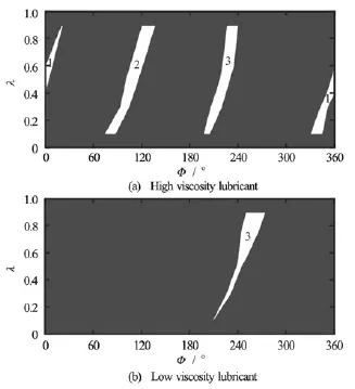
Fig.7 Oil film ruptures in experiment at N =3000 r/min, pin=0.3MPa
Figure 7 and Fig.8 show the graphical comparison of oil film ruptures under different input pressures.It is shown that with the increase of the input pressure, for the high viscosity lubricant, the oil film rupture location moves indistinctly along the rotation direction of the axis, the oil film reformation location moves along the opposite rotation direction of the axis, and the cavitation area decreases. It is consistent with the experimental results of the high viscosity lubricant, with the increase of the input pressure, the cavitation area decreases distinctly and the oil film rupture occurs only at the oil groove 3 for the low viscosity lubricant. The quality of lubrication is improved for the low viscosity lubricant compared with the high viscosity lubricant.
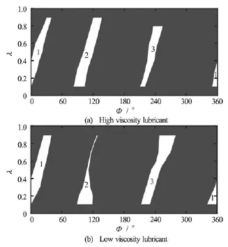
Fig.8 Oil film ruptures in experiment at N =3000 r/min, pin=0.1MPa
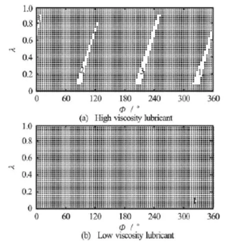
Fig.9 Oil film ruptures in theory at N =1800 r/min,pin= 0.3 MPa
Figure 9 and Fig.10 show the graphical comparison of the theoretical results for the oil film ruptures for different viscosities, in which the white areas are the cavitaion region, the black areas are the oil film full region. It is shown that with the increase of the rotating speed, the rupture area of both the low and high viscosity lubrications increases distinctly. In a low rotating speed, the oil film rupture occurs at the three oil grooves for the high viscosity lubricant, but the oil film rupture occurs indistinctly for the low viscosity lubricant. In a high rotating speed, the oil film rupture occurs distinctly at the three oil grooves for both the low and high viscosity lubrications; the cavitation area decreases for the low viscosity lubricant as compared with the high viscosity lubricant.
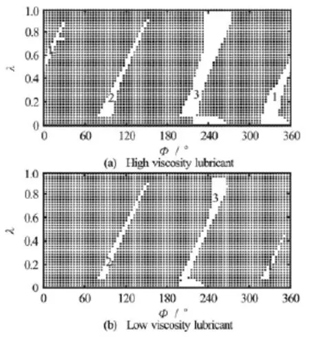
Fig.10 Oil film ruptures in theory at N =10000 r/min, pin=0.3MPa
Figure 9 and Fig.6 show the graphical comparison of the theoretical results and the experimental results for the oil film ruptures. It is shown that though there are some differences between the theoretical results and the experimental results, especially for the oil wedge 2 of the high viscosity lubricant and the oil wedge 3 of the low viscosity lubricant, the theoretical results obtained by the modified Elrod cavitation algorithm agree with experimental results generally. The experimental cavitation region is larger than the theoretical cavitation region, which can be explained as follows. In the experiment, there might be a tension in the oil film, as well as the formation of new cavitations and other ingredients; in theory, the ingredients in the experiment are not considered and it is assumed that the flow is Newtonian, the lubricant inertia effect is small.
By a comparison of Figs.6 and 9, it can be seen that the theoretical results agree with experimental re-sults generally, therefore, we can forecast the oil film ruptures by theoretical results at a super high speed, which may help the design of high speed journal bearings and improve the rotating speed of the bearing.
5. Conclusions
The cavitation shape, the oil film rupture and reformation location, and the cavitation area of the spiral oil wedge sleeve bearing are studied theoretically and experimentally for both the high viscosity lubricant and the low viscosity lubricant.
(1) The cavitations are strip-shaped for both the high viscosity lubricant and the low viscosity lubricant, with the cavitation leading end in a closed angle, and in the oil film rupture region, oil bubbles are produced at a high speed. The cavitations for the high viscosity lubricant is distinct, but the cavitations for the low viscosity lubricant is indistinct.
(2) With the increase of the rotating speed, the cavitation area of the oil wedge becomes larger for both the high viscosity lubricant and the low viscosity lubricant, with the increase of the input pressure, the cavitation area of the oil wedge decreases for both the high viscosity lubricant and the low viscosity lubricant, the effect of the input pressure on the cavitation is larger than that of the rotation speed generally.
话别说得这么难听好不好?我说过我和他根本就不认识!事情闹得沸沸扬扬满城风雨对你我有什么好处?就算你把他告进监狱又能怎样?能解决问题吗?你是不是非要把我弄得身败名裂?
(3) The cavitation area decreases and the quality of lubrication is improved for the low viscosity lubricant compared with the high viscosity lubricant.
(4) The experimental results agree with the theoretical results generally, which shows the theoretical computation is valid.
Acknowledgement
This work was supported by the Scientific Research Foundation of Shandong University of Science and Technology for Recruited Talents (Grant No. 2013RCJJ014).
[1] RIEDEL M., SCHMIDT M. and STÜCKE P. Numerical investigation of cavitation flow in journal bearing geometry[J]. EPJ Web of Conferences, 2013, 45(45): 01081/1-01081/4.
[2] WU Jian-kang, LI An-feng and LEE T. S. et al. Operator-splitting method for analysis of cavitation in liquidlubricated herringbone grooved journal bearing[J]. Journal of Hydrodynamics, 2002, 14(4): 95-101.
[3] WU J., LI A. and LEE T. S. et al. Operator-splitting method for the analysis of cavitation in liquid-lubricated herringbone grooved journal bearings[J]. International Journal for Numerical Methods in Fluids, 2004, 44(7): 765-775.
[4] BRAUN M. J., HANNON W. M. Cavitation formation and modelling for fluid film bearings: A review[J]. Proceedings of the Institution of Mechanical Engineers, Part J: Journal of Engineering Tribology, 2010, 224(9): 839-863.
[5] FANG Chao-feng. Study of dynamically loaded journal bearing with transference of transient oil film[D]. Master Thesis, Shanghai, China: Shanghai University, 2007(in Chinese).
[6] LI Q., YU G. and LIU S. et al. Application of CFD analysis for journal bearing considering cavitation effects[J]. Journal of Engineering Thermophysics, 2010, 31(Suppl): 221-224.
[7] SU Hong, WANG Xiao-jing and ZHANG Zhi-ming. History moving of cavitation for dynamically loaded journal bearing[J]. Chinese Journal of Mechanical Engineering, 2006, 42(4): 8-12(in Chinese).
[8] LI Qiang, ZHENG Shui-ying and LIU Shu-lian. Analysis of the performance of journal bearing with JFO boundary condition[J]. Journal of Mechanical Strength, 2010, 32(2): 270-274(in Chinese).
[9] MENG F., LONG T. Study film temperature including cavitation effect of sliding bearing by CFD method[J]. Advanced Materials Research, 2013, 690-693: 2012-2015.
[10] SHYU S.-H., JENG Y.-R. and LI F. A legendre collocation method for thermohydrodynamic journal-bearing problems with Elrod’s cavitation algorithm[J]. Tribology International, 2008, 41(6): 493-501.
[11] HATAKENAKA K., TANAKA M. Thermohydrodynamic performance of journal bearings with partial reverse flow and finger-type cavitation[J]. Proceedings of the Institution of Mechanical Engineers, Part J: Journal of Engineering Tribology, 2002, 216(5): 315-325.
[12] BAYADA G., MEURISSE M. H. Impact of the cavitation model on the theoretical performance of heterogeneous slip/no-slip engineered contacts in hydrodynamic conditions[J]. Proceedings of the Institution of Mechanical Engineers, Part J: Journal of Engineering Tribology, 2009, 223(3): 371-381.
[13] OUJJA R. A new method for cavitations approximation in some general lubrication devices[J]. Applied mathematics and computation, 2006, 181(2): 1645-1656.
[14] WANG X., ZHANG J. and DONG H. Analysis of bearing lubrication under dynamic loading considering micropolar and cavitating effect[J]. Tribology International, 2011, 44(9): 1071-1075.
[15] WANG X., ZHU K. Numerical analysis of journal bearings lubricated with micropolar fluids including thermal and cavitating effects[J]. Tribology International, 2006, 39(3): 227-237.
[16] LI X., SONG Y. and HAO Z. et al. Cavitation mechanism of oil-film bearing and development of a new gaseous cavitation model based on air solubility[J]. Journal of Tribology, 2012, 134(3): 031701-031707.
[17] GELLER M., SCHEMMANN C. and KLUCK N. Simulation of radial journal bearings using the FSI approach and a multi–Phase model with integrated cavitation[J]. Progress in Computational Fluid Dynamics, 2014, 14(1): 14-23.
[18] COLE J. A., HUGES C. J. Visual study of film extent in dynamically loaded complete journal bearings[C]. IME Conference on Lubrication and Wear. London, UK, 1957.
* Project supported by the National Natural Science Foundation of China (Grant No. 51305242).
Biography: WANG Li-li (1979-), Female, Ph. D., Lecturer
猜你喜欢
杂志排行
水动力学研究与进展 B辑的其它文章
- United friction resistance in open channel flows*
- Ski jump trajectory with consideration of air resistance*
- Selection of organic Rankine cycle working fluids in the low-temperature waste heat utilization*
- Stability of a tumblehome hull under the dead ship condition*
- Multi-scale Runge-Kutta_Galerkin method for solving one-dimensional KdV and Burgers equations*
- Numerical study of the performance of multistage Scaba 6SRGT impellers for the agitation of yield stress fluids in cylindrical tanks*
