Design and Analysis of Axial Thrust Roller-Exciting Vibrating Table and Its Motor-Control System Based on Co-simulation
2015-01-12WUShangsheng吴上生LUZhenwei陆振威HUANGZexing黄泽星ZHOUYunqi周运岐
WU Shang-sheng (吴上生), LU Zhen-wei (陆振威), HUANG Ze-xing (黄泽星), ZHOU Yun-qi (周运岐)
1 School of Mechanical and Automotive Engineering, South China University of Technology, Guangzhou 610640, China2 Shaoneng Group Shaoguan Hongda Gear Co., Ltd., Shaoguan 512029, China
Design and Analysis of Axial Thrust Roller-Exciting Vibrating Table and Its Motor-Control System Based on Co-simulation
WU Shang-sheng (吴上生)1*, LU Zhen-wei (陆振威)1, HUANG Ze-xing (黄泽星)1, ZHOU Yun-qi (周运岐)2
1SchoolofMechanicalandAutomotiveEngineering,SouthChinaUniversityofTechnology,Guangzhou610640,China2ShaonengGroupShaoguanHongdaGearCo.,Ltd.,Shaoguan512029,China
Aiming at improving the mechanical vibrating equipment, the axial thrust roller-exciting vibrating tables and its motor-control system based on co-simulation were put forward. First, the structures of vibrating table and its surface equations and boundary conditions were established through reversal process. Second, waveform distortion influenced by random and harmonic waves was analyzed by equivalent parametric transition. These two steps were both technological challenge and contribution for the vibrating table. Finally, based on research above, a proportion integration differentiation (PID) motor-control system was built to show its rapid operation and convenient control. All the results show that not only does vibrating table have lower waveform distortion than traditional ones, but its control system narrows down the fluctuation and improves anti-interference performance. Hence, it provides a more extensive selection for efficient and practical mechanical vibrating table.
vibratingtable;surfaceequation;waveformdistortion;co-simulation
Introduction
Vibrating table, especially large-tonnage with high frequency driven by electric or hydraulic motor[1-3], has developed rapidly and has a wide range of applications in industry, agriculture, and aerospace. It’s no doubt that it has been an important indicator for high-tech field. Traditional mechanical vibrating tables such as eccentric block or crank rocker don’t perform well due to structural limit[4]: the former has maximal amplitude of 10 mm and 10 g acceleration with frequency ranged from 5 to 100 Hz, while the latter amplitude[5]can reach 100 mm and the same acceleration as former within frequency of 50 Hz. In spite of low manufacturing cost and convenient maintenance, both of them are faced with problems like serious waveform distortion, low upper frequency limit, and inconvenient control[6].
Hence, an axial thrust roller-exciting vibrating table[7]is put forward. Both the technical challenge and contribution are to establish vibrating surface with low waveform distortion, make equivalent transition from different errors to parametric setting[8], and adopt co-simulation to design the proportion integration differentiation (PID) motor-control system.
1 Structure of Axial Thrust Roller-Exciting Mechanical Vibrating Table
Axial thrust roller-exciting vibrating table is a device that converts motor rotation into axial vibration with high frequency and amplitude. As Fig.1 shows, the vibrating table mainly includes limited part (1, 10, 29, and 30), exciting part (2, 3, and 7-9), regulator (4-6, 21, and 22), and driving part (11-16 and 18).
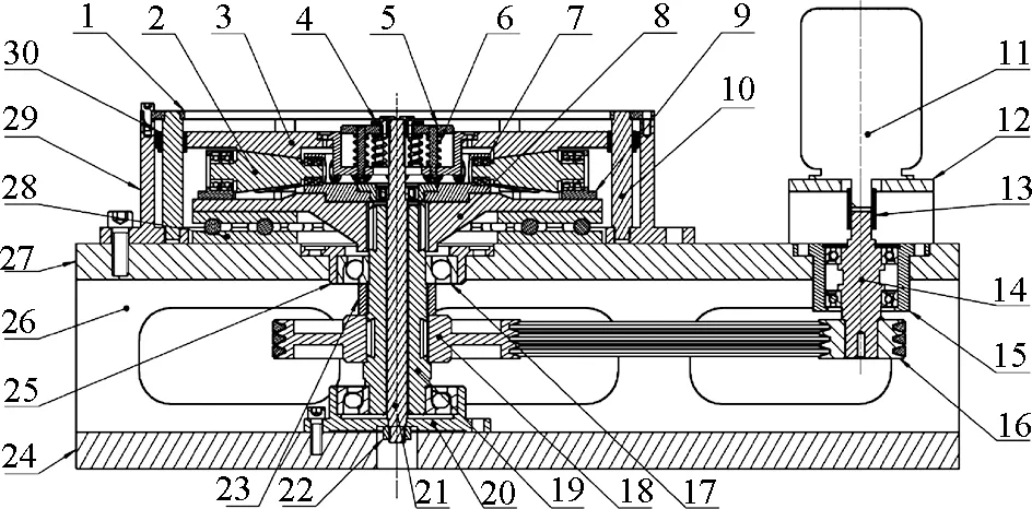
1-top flapper; 2-tapered roller; 3-vibrating platform; 4-regulator; 5-spring lip; 6-spring; 7-bearing block (1); 8-roller seat; 9-bearing block (2); 10-tangential pin; 11-motor; 12-motor rack; 13-coupling; 14-shaft of driving belt wheel; 15-bearing block (3); 16-driving wheel; 17-spindle bearing; 18-subordinate wheel; 19-spindle; 20-bearing block (4); 21-pull bar; 22-nut; 23-sleeve; 24-bottom framework; 25-bearing block (5); 26-flank framework; 27-top framework; 28-end bearing; 29-located block; 30-gleitbuechsenFig.1 Structure of axial thrust roller-exciting vibrating table
In the driving part, the driving belt-wheel is connected to motor shaft by a coupling while subordinate wheel transfers motor torque to the spindle and protect from overloading through the belt.
In the exciting part, the tapered rollers rotating around the spindle will generate axial vibration. Meanwhile, according to meshing effect between vibrating platform and tapered rollers, spindle torque is decomposed into axial exciting vibrating force and tangential force. In a vibrating period, tangential pin unloads tangential force and facilitates axial motion.
In the limited part, axial vibration is oriented by pull bar and tangential pin. The tapered rollers always keep touch with circumferentially concavo-convex surface on vibrating platform. In order to decrease abrasion between roller and vibrating platform and improve output waveform, each end of tapered roller is installed at double-row bearing fixed on bearing block (2) and roller seat. This allows rollers to make self-rotation while rotating around the spindle.
In the regulator part, there is a spline keyway in the centre of the roller seat supported by the end bearing. The end bearing is to connect spindle and unload the axial force from roller seat. In order to avoid severe jump or deviation of the vibrating platform, one end of the pull bar connected to bottom framework by nut while the other end assembled with spring lip is to set preloads of spring directly and meanwhile regulate pre-frequency indirectly. Moreover, it can help to improve vibrating waveform distortion from sudden change of motor speed or mechanical shock.
2 Design of Vibrating Curved Surface
2.1 Request of vibration
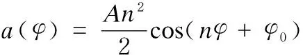
In order to improve frequency but lower abrasion for the vibrating surface platform and rollers caused by sudden change of contact stress and avoid the maximal derivative of acceleration, cosine acceleration is adopted,
a=amaxcos(nωt+λ0).
(1)
Then take the initial conditions into account,
t=0, v=0, s=0,
t=φ0/(2ω), s=A.
(2)
So the formulas are deduced as follows
(3)
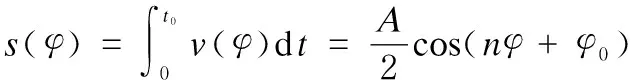
(4)
whereAis the amplitude,ωis the angular velocity,φis the angular displacement,φ0is the angular displacement in a vibrating period, andnis the number of tapered rollers.
2.2 Mathematical model of vibrating surface
Referred to cam design, reversal process is applied to simplifying establishment of vibrating surface. Imagines vibrating platform is static, each roller makes a synthetic motion combined rotation at the angle velocityω, and axial similar harmonic motion complies with
sT(φ)=-s(φ)|λ0=0.
(5)
Based on a base circle whose radius isR, takes a roller as an object, and then unfolds vibrating surfaceSRT(φ) with appropriate coordinate translation. As shown in Fig.2, a new curve is obtained,

(6)
whereκ=κ(R) is the curved ratio in different radius. In Fig.2,ORis the center of tapered roller and its radius isr, andRis the radius of base circle whileRaandRfare its maximal and minimal radii.
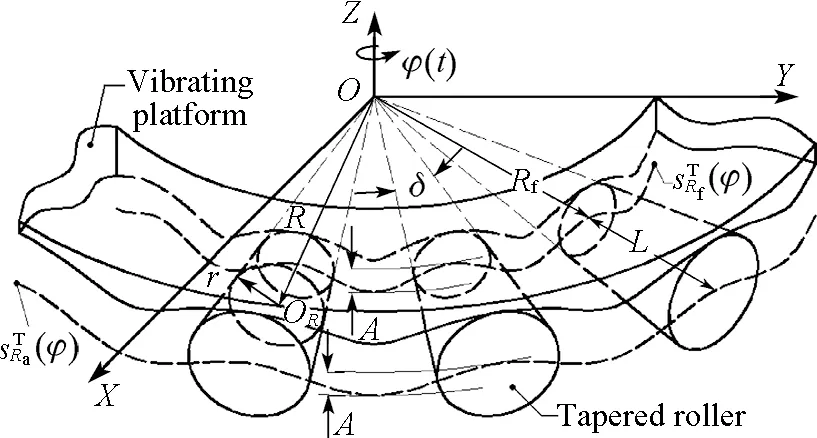
Fig.2 Sketch of vibrating platform and rollers
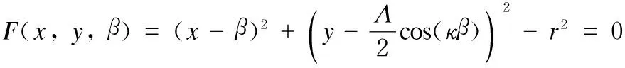
Using Eq. (6), we takeX-axis as the rotating direction andY-axis as the axial direction[9], and single parametric functions of surface are
(x-β)2+(y-Γ(β))2=r2,
(7)
(8)
(9)
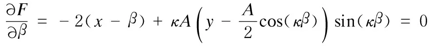
whereβis the parameter of variable curvature. Then the function of theoretical profilogram onC0(Γ(β),β) sectionORis
(10)
But actually, the effective object is not pointORbut sectionOR. Figure 3 shows the geometric relations.
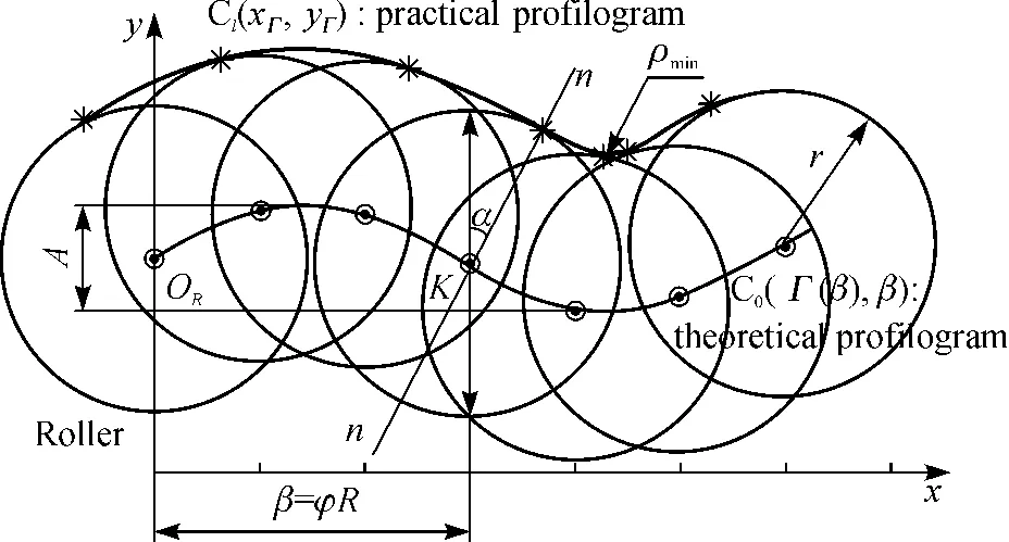
Fig.3 Unfolded curve based on section OR in Fig.2
Those written below must be taken into account:
κ=n/R,
(11)
r=R tan(δ/2)=R tan(π/(2n)),
(12)
β=φR,
(13)
whereδis the cone angle of roller. From Eqs. (8) - (13), the practical surface parametric function is obtained,
2.3 Pressure angle and its boundary conditions
When the base circle radius increase, the theoretical surfaceSRT(φ) becomes flatter with the decrease in the pressure angle[9]. In Fig.3, taking pointKas the object and drawing a normaln-n, the included angle of the linen-nandY-axis is the pressure angle,
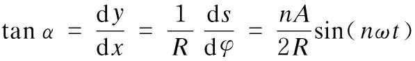
(16)
Due to the existence of cone angle of rollerδ, the actual contact point at the unfolded practical profilogramC1(Г(β),β) isfshown in Fig.3, and a detailed analysis for roller is shown in Fig.4.
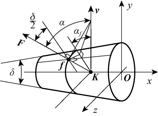
Fig.4 Analysis of the pressure angle based on section OR
The relation between angles is that
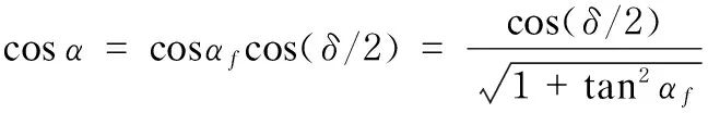
(17)
Combining Eqs.(16) and (17), the pressure angle is
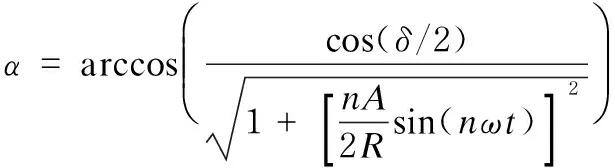
(18)
Equation (18) indicates that pressure angle will change over time and base circle radius. Hence, the minimal base circle radius (Rf), the pressure angle, and the minimal curvature radius (ρmin) must meet the boundary as
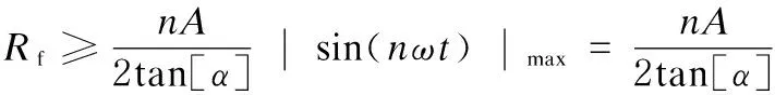
(19)
(20)
(21)
In conclusion, the main geometric parameters of vibrating surface are initially set in Table 1.
Table 1 Main geometric parameters of vibrating surface
ParametersValueAmplitude/mm20Numberofrollern12TheminimalradiusoftheminimalbasecircleRf/mm200ThemaximalradiusoftheminimalbasecircleRa/mm300LengthofrollerL/mm100Radiusofrollerinsmallendrmin/mm52.66Themaximalpressureangleαmax/(°)28.6Theminimalcurvatureradiusρmin/mm4.65
According to the design requirement listed in Table 2 and the equation mentioned above, the model of vibrating table is shown in Fig.5.
Table 2 Technical design indicators of vibrating table

IndicatorValueTablesize/mm800Themaximalload/kg100Themaximalvibratingforce/N4700Velocityofpeak/(m·s-1)7.5Themaximalacceleration/(m·s-2)12g*Rangeoffrequency/Hz0.1-120
Note:*is gravitational acceleration
Fig.5 3D model of vibrating table
3 Error Analysis of Acceleration Waveform
3.1 Analysis of random and harmonic wave
Fundamental wave of acceleration is accompanied with random wave and high-end harmonic wave because of several reasons[10]. For random wave (error), it is manufacturing quality that influences size-accuracy, roughness, and so on. This can be classified into normal distribution[11]and its mean-value and standard deviation follow the same random sequence. It means that all random waves are under the same ±3σ, as shown in Fig.6.
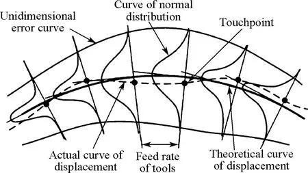
Fig.6 Displacement error of vibrating surface
High-end harmonic wave which is attributed to nonlinear contact and instant shock in high-speed situation results in residual oscillation. In simulation for vibration, harmonic wave is transited to elasticity and damping by Augmented Lagrangian and Impact function (shown in Fig.7, the contact stiffnessK=Eε), which are adopted to calculate contact force under convergence[12]. Here, the Young modulusE=200 GPa and depth of overlap areaε=10-3mm.
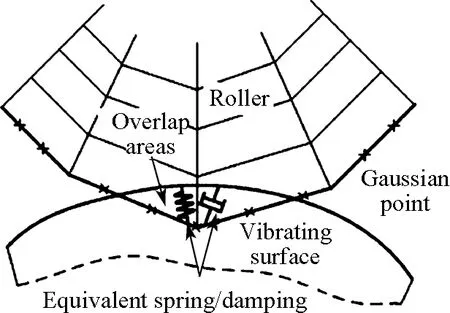
Fig.7 Equivalence of overlap area between two contact-parts
3.2 Simulation of vibrating table
Apart from parts irrelevant to motion, the model is set 48 components, 18 low pairs, 12 3D-contacts, 1 spring and 1 torque. The parameters are shown in Table 3 and output waveform without loading is obtained shown in Fig.8.
Table 3 Dynamics simulation parameters
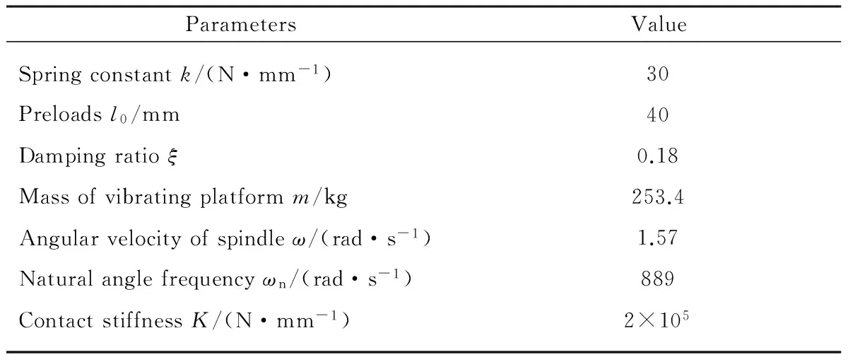
ParametersValueSpringconstantk/(N·mm-1)30Preloadsl0/mm40Dampingratioξ0.18Massofvibratingplatformm/kg253.4Angularvelocityofspindleω/(rad·s-1)1.57Naturalanglefrequencyωn/(rad·s-1)889ContactstiffnessK/(N·mm-1)2×105
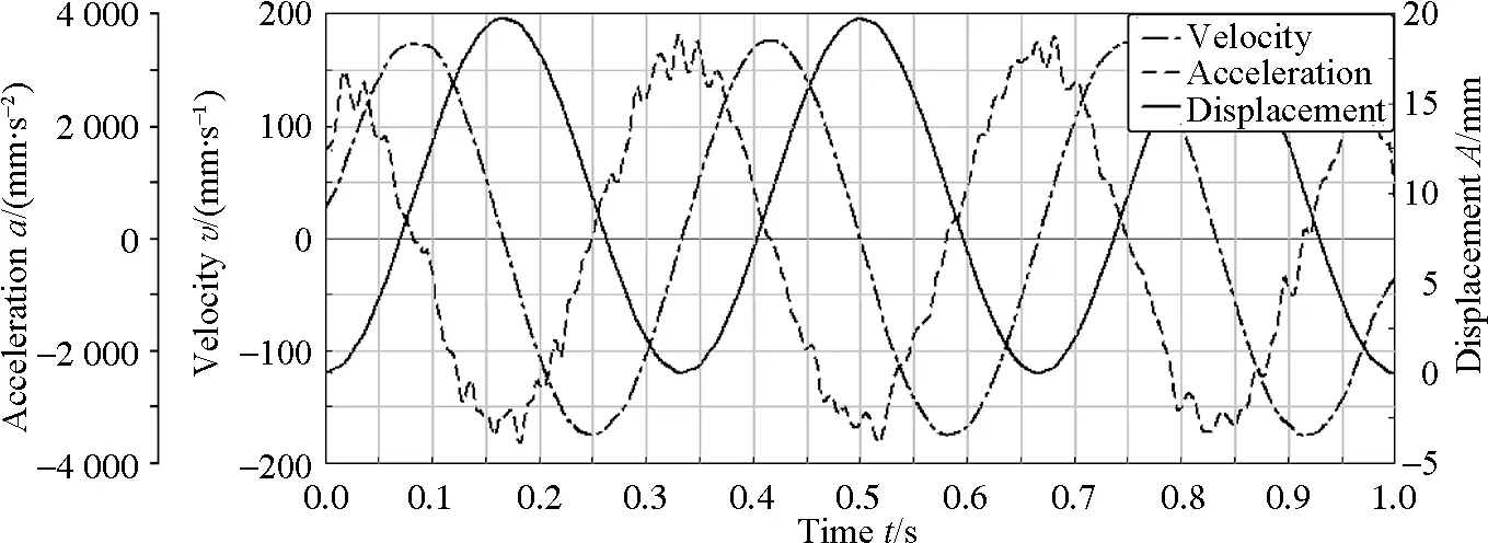
Fig.8 Vibration table output waveform
All waveforms conform to sine function. But as calculating time increases, there are obvious fluctuations at peaks. To make further explanation, on one hand, both velocity and pressure angle have reach their maximum at the same time, so the declining transmission performance leads to less stability of output; on the other hand, fluctuations are related to numerical algorithms, sampling frequency, and so on.
3.3 Study of waveform distortion
Waveform distortion is a primary factor affecting the vibrating precision. First, select the target frequency: 1, 50, and 100 Hz and then make an FFT translation to analyze its frequency characteristic by MATLAB[13]. Then remove the fundamental wave and harmonic wave[14]. Finally, transform the random wave into sine-harmonic wave and calculate the standard deviation[15]. The equivalent transition of amplitude is
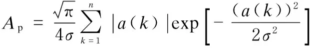
(22)
whereApis the equivalent amplitude,nis the sampling number,a(k) is the different acceleration amplitude in each random wave, andσis the variance ofa(k). Frequency spectra (A(f) is the amplitude of acceleration under the special frequency) and equivalent sine wave spectra are shown in Fig.9.
According to the definition of waveform distortion in ISO/TS108/WG4N12, select more than 10 points of equivalent harmonic[16]but not fundamental wave on spectrum and calculate waveform distortion:
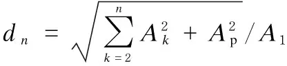
(23)
whereAkis the amplitude of harmonic wave,A1is the amplitude of fundamental wave. The waveform distortion ratiosdnare 9.94%, 8.62%, and 11.34%, respectively.
According to the IEC standard, waveform distortion of vibrating table should be under 25%, but quite a few traditional mechanical vibrating tables could meet this target. The distortion ratio of Y5070 mechanical vibrating table is 35% under the targeted frequency of 60 Hz, but this table’s is 11.34% under the frequency of 100 Hz. The simulation also reflects that the vibrating table has better performance in the middle frequency range. When the table operates at low frequency, the amplitude of harmonic wave and random wave are higher than the amplitude of fundamental wave. As the amplitude of fundamental wave increases, the relative ratio decreases. But meanwhile both frequency and residual oscillation will increase.


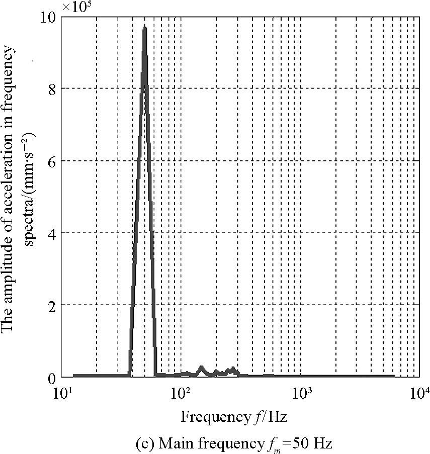

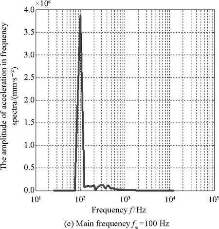

Fig.9 Frequency spectra ((a), (c) and (e)) and equivalent sine wave spectra ((b), (d), and (f)) of different output vibration frequencies
4 Design and Analysis of Motor-Control System for Vibrating Table
4.1 System design based on PID method
To make a further improvement in output accuracy and decrease startup-time, a PID motor-control system[17]is designed by ADAMS and MATLAB. High driving frequency is used at the beginning. After the inertia of system is overcome, signal turns into expected frequency[18]. In the process, torque is regulated by displacements.
The system includes PID module, DC motor module, loading and feedback circuit. “Displacement-frequency” module feedbacks output to the front end of system for greater stability and constant output. Meanwhile, angular velocity feedbacks signal to motor through the calculation of counter electromotive force and angular transmission. PID parameters are designed by optimized “Ziegler-Nichols” and parameter setting[19-22]asKP=825,KI=35, andKD=36. Simulated parameters are shown in Table 4 and system is built shown in Fig.10.
Table 4 Main parameters for system simulation
ParametersValueLoadM/kg50Coefficientofslidingfrictionf0.15ResistanceofcircuitRc/Ω2.5InductanceofDCmotorLc/mH3.8ConstantofcounterelectromotiveforceinDCmotorCe/(N·m·A-1)0.273ConstantoftorqueinDCmotorCm/(N·m·A-1)0.273TransmissionratioofbeltK2Simulationstep500Simulationtimet/s2.5

Fig.10 PID motor-control system based on co-simulation between ADAMS and MATLAB
4.2 Co-simulation test and analysis of system

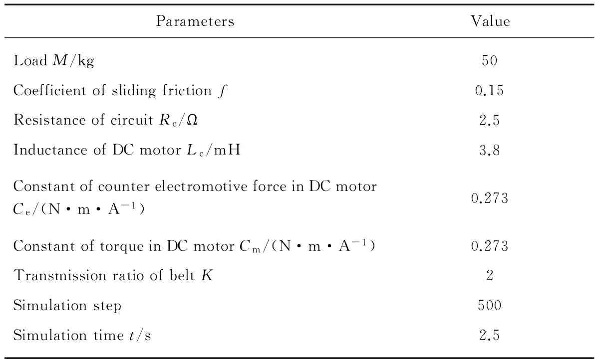
Due to change of pressure angle in operation, the loading also changes over time. Both the angular velocity and vibrating frequency have effects on feedback. Figure 12 indicates that under the same condition mentioned above, spindle have reached dynamic stability within 1 s, when steady angular velocityω=5π/6 (rad/s). In the steady period, the maximal fluctuation of angular velocity ranges in ±7% and its maximal error is 4.7%.
Fig.11 Axial displacement and velocity of vibrating table

Fig.12 Angular velocity of spindle
Because of motor’s power limitation, the torque output must get through two periods of regulation. Figure 13 shows that at stage I, motor rapidly runs with full load after a short transition. After that, it quickly lowers and then keeps the output in stage II so as to stabilize the angular velocity. It means that at the cost of the responsive time, the vibrating table is protected from sudden shock result from the initial high overshoot and PID control has greater stability and anti-interference performance than the original one without regulation.
5 Conclusions
The achievements of this paper are listed as follows.
(1) A new mechanical vibrating table is put forward and its surface equations and boundary conditions are established by the envelope principle and reversal process.
(2) The virtual prototype of vibrating table is built and the simulated results show that the vibrating table can generate higher acceleration and amplitude with lower waveform distortion than traditional mechanical one.
(3) Based on co-simulation between ADAMS and MATLAB, torque from motor is controlled stably through a PID displacement feedback system. Meanwhile, the range of frequency and anti-interference performance of the system are better than design requirements.
Despite improvements on waveform accuracy, upper vibrating limit and easy regulation, outputs in lower and higher frequency range don’t reach our expectation and the tapered rollers will suffer severe abrasion. But we will keep trying and make further research on it.
[1] Xing T, Zuo Q, Yang Y S,etal. Progresses of Research on Hydraulic Vibration Technology [J].ChinaMechanicalEngineering, 2012, 23(3): 362-377. (in Chinese)
[2] Xu Y. Design and Experimental Research of the 20T Electro-Hydraulic Shaking Table [D]. Hangzhou: Zhejiang University of Technology, 2009: 1-8. (in Chinese)
[3] George F L, Dave S. Understanding the Physics of Electro-Dynamic Shaker Performance [J].SoundandVibration, 2001, 35(10): 24-33.
[4] Xue Y, Ling X Z, Lu N L,etal. Progress of Application and Research on Mechanical Vibration Technology in Engineering [J].ChineseJournalofRockMechanicsandEngineering, 2005, 24(S2): 5901-5908. (in Chinese)
[5] Liu D B, Huan H X.The Research and Developing Trend of Vibration Testing Method [J].EnvironmentalTechnology, 2006(3): 21-25. (in Chinese)
[6] Chen Z W, Yu H J. Existing State and Development of Vibration Control Technology [J].JournalofVibrationandShock, 2009, 28(3): 73-77. (in Chinese)
[7] Wu S S, Lu Z W, Huang Z X,etal. Axial Thrust Rotating Roller-Exciting Mechanical Vibration Device: CN, 201310064147.2[P]. 2013-02-28.
[8] Li B M, Qian Z B, Cheng H J,etal. Co-simulation of Engine for AUV in ADAMS and MATLAB [J].JournalofSystemSimulation, 2010, 22(7): 1668-1673. (in Chinese)
[9] Churchill F T, Hansen R S. Theory of Envelopes Provides New Cam Design Equation [J].ProductofEngineering, 1962, 35: 45-55.
[10] Yang S M. Technical Requirements and Verifications of Mechanical Vibration Table [J].AeronauticStandardization&Quality, 1978(4): 25-29. (in Chinese)
[11] Kim H R, Newcombe W R. The Effect of Cam Profile Errors and System Flexibility on Cam Mechanism Output [J].MechanismandMachineTheory, 1982, 17(1): 57-72.
[12] Li Z G. Detailed Introduction and Examples for ADAMS [M]. Beijing: National Defence Industry Press, 2010: 205-222. (in Chinese)
[13] Wei Y D. Approximate Analytical Solution of Waveform Distortion of Ultra-Low Frequency Standard Vibrator [J].JournalofVibrationandShock, 2000, 19(3): 49-52. (in Chinese)
[14] Sun N, Li G X. A Simple Method for Generating the Simulating Signals of Random Vibrations [J].JournalofVibrationandShock, 2000, 19(2): 50-51. (in Chinese)
[15] Wu D B. Measurement Research of Random Vibration Acceleration Value and Power Spectral Density [J].MeasurementTechnique, 1985(12): 4-7. (in Chinese)
[16] Yang Q Y, Shu Y L.Distortion of Low Frequency Standard Vibration Table and Measurement Methods [J].WorldEarthquakeEngineering, 2011, 27(2): 185-189. (in Chinese)
[17] Yin D Y, Huang Y T, Liu Y F. Simulation of Double-Motor Speed Tracking Servo System Based MATLAB/Simulink [J].JournalofChineseInertialTechnology, 2011, 19(2): 299-233. (in Chinese)
[18] Zhao Y L, Zhang C J, Zhang H Z. United Simulation about Mechanical and Control System of Missile Seeker [J].JournalofProjectiles,Rockets,MissilesandGuidance, 2009, 29(4): 77-79. (in Chinese)
[19] Karl J A, Richard M M. Feedback Systems: an Introduction for Scientists and Engineers [M]. State of New Jersey: Princeton University Press, 2008: 293-344.
[20] He Y, L C M. Research and Application of Preferences in PID Controlling System [J].ComputerEngineeringandDesign, 2006, 27(8): 1496-1498. (in Chinese)
[21] Werner U. Theoretical Rotor Dynamic Analysis of Two-Pole Induction Motors Regarding Excitation due to Static Rotor Eccentricity [J].ArchiveofAppliedMechanics, 2011, 81(2): 241-262.
[22] Ren J J, Liu Y C, Zhao Y T,etal. Research on the Direct Torque Control System of PMSM with Propeller Load [J].ElectricMachinesandControl, 2012, 16(7): 45-51. (in Chinese)
Foundation items: Technological Innovation of Science-Technology Oriented Small to Medium Enterprises, China (No. 12C2621440522); Guangdong Province’s Transportation Ministry Planning Program of Science and Technology, China (No. 201202088)
TS803 Document code: A
1672-5220(2015)01-0041-07
Received date: 2014-05-12
* Correspondence should be addressed to WU Shang-sheng, E-mail: sai81401281@163.com
杂志排行

Journal of Donghua University(English Edition)的其它文章
- Mechanical Property and Crystal Structure of Poly(p-phenylene terephthalamide) (PPTA) Fibers during Heat Treatment under Tension
- Diatomite Precoated Nonwoven Membrane Bioreactor for Domestic Wastewater Reclamation
- Supported Manganese Oxide on Graphite Oxide: Catalytic Oxidation of Nitrogen Oxide in Waste Gas
- Preparation and Properties of Polylactic Acid (PLA)/Nano-SiO2 Composite Master Batch with Good Thermal Properties
- Scheduling Rules Based on Gene Expression Programming for Resource-Constrained Project Scheduling Problem
- Dynamic Analysis of Some Impulsive Fractional-Order Neural Network with Mixed Delay