A study on control method of new type UAV
2015-01-12KenjiNishigakiKoheiKawakamiShinIchiroNishidaMasaharuNishimuraKazunoriSakurama
Kenji Nishigaki, Kohei Kawakami, Shin-Ichiro Nishida, Masaharu Nishimura, Kazunori Sakurama
(Department of Mechanical and Aerospace Engineering, Tottori University,4-101 Koyama-Minami, Tottori, 680-8552 Japan)
It is difficult for people to enter into a disaster site and a danger zone. Therefore, small UAV(s) are used for check, and observation of disaster site. Especially, rotor wings type UAV has two advantages. It can perform detailed check and observation by hovering and don’t need landing strip by vertical takeoff and landing. In order to perform observation in high accuracy, improvement in flight stability and miniaturization are called for. Since the body rotates by the anti-torque which arose from main rotor rotation, the body requires an anti-torque compensation mechanism. Although a general anti-torque compensation mechanism is a tail rotor, there is a problem that the whole body becomes large by tail rotor. We propose new rotor wings type UAV(SWUM[Stator Wing Under Main rotor]) which negates anti-torque using stator wing[1,2].
1 New type UAV (SWUM)
The basic concept of proposed SWUM is illustrated in
Fig.1. Stator wings are attached to the body under a main rotor. Therefore, this body is smaller than the conventional UAV. Rotation of the main rotor not generates only downwash but an anti-torque. A stator wing generates a lift force by hitting downwash. SWUM controls attitude angle around yaw axis using the lift force of a stator wing. A prototype of SWUM is shown in
Fig.2. Each stator wing can be tilted independently by the actuator attached to each root[1,2].
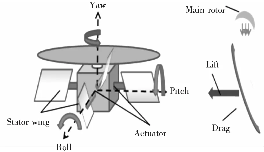
Fig.1 The basic concept figure of SWUM

Fig.2 A prototype of SWUM
2 Attitude control around yaw axis
The attitude control test around yaw axis was performed using the stator wings.
2.1 Experimental equipment
The attitude control test around yaw axis was conducted by using the SWUM prototype on the free rotational table. We have built an attitude control system using the microcomputer, IMU sensor and actuators of stator wings. A sensor value was recorded by small logger (open log). The whole composition experimental equipment is shown in
Fig.3.
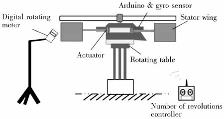
Fig.3 The whole of the composition experimental equipment
2.2 Control method
Arithmetic processing for attitude angle control around yaw axis was performed with a microcomputer from date at the gyroscope sensor attached to the body. All stator wings were controlled with the same angles. The control block diagram is shown in
Fig.4[3].

Fig.4 Block diagram of yaw attitude control system
2.3 Experimental result
Reference angle was at 0 deg. We defined 0 deg as the front direction of the body of a sensor startup time. The free rotational table was fixed until a main rotor becomes constant speed rotation. The testing results of the body attitude and angle of stator wing are shown in
Fig.5.
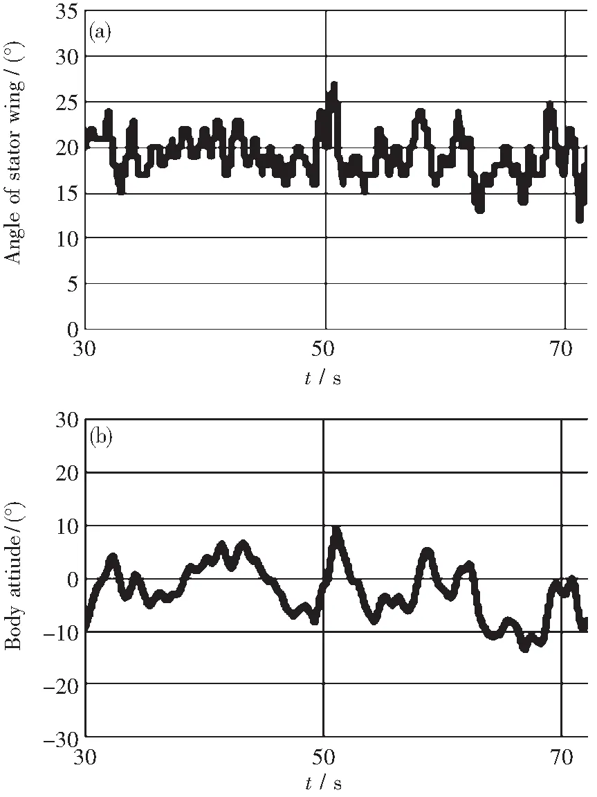
Fig. 5 Result of attitude control testing around yaw axis(a)—Angle of stator wing; (b)—Body attitude
The attitude control function around the yaw axis by stator wings was confirmed. The control error depends by the delayed motion of the actuator modules.
3 The horizontal translational motion
Most of the rotor type UAV has a pitch angle control mechanism of the main rotor being blades called a swash plate. The horizontal motion of such UAV is achieved by tilting the body using swash plate. However, the mechanism of a swash plate is complicated. Similarly, the method of tilting the body was adopted the horizontal translational motion of SWUM. Method of tilting the body proposed using not a swash plate but stator wings. A stator wing generates not only a lift force but drag force. The horizontal translational motion will be achieved by tilting the body using difference of the lift force and drag force of each stator wing. Since the swash plate is unnecessary in structure of UAV, the structure of the body become simpler than the conventional UAV. We created the mathematical model of the kinetics of this vehicle. Each body coordinate system and inertial system is expressed by subscript "B" and subscript "I". Stator wing’s lift and drag are expressed by “L” and “D”. Main rotor’s anti-torque and thrust force are expressed by “Q” and “T”. The moment of inertia of the body and main rotor are expressed by “I” and “Ir”. Horizontal distance and vertical distance from the center of the gravity are expressed by “r” and “h”[1].

(1)
(2)
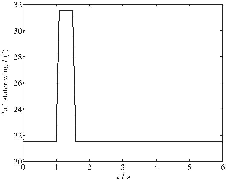
Fig.6 “a” Stator wing angle
However, the air damper is not taking into consideration this time.
4 Simulator
The dynamics simulator of SWUM was created the Eq.1 and Eq.2. The example of simulation result was shown in
Fig.6~9. In this simulation, torque around pitch axis at body was applied to the body by a stator wing. Given torque was about 0.612 N·m. The sampling period of the simulation was set to 0.1 ms. History of the angle of stator wings are shown in
Fig.6~7. The following things were checked from a simulation result. It is checked whether the body carries out a precession movement by stator wings. The result of movement of the rotation center was about 8 degree around x axis. The simulation results are shown in
Fig.8~9.
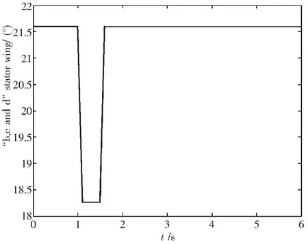
Fig.7 “b”,“c”,“d” Stator wing angle

Fig.8 Roll angle
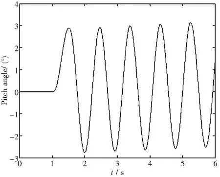
Fig.9 Pitch angle
The result expected from the simulation result was obtained. It was considered that the simulator worked correctly.
5 Conclusions
In this research, we designed the drive unit of the stator wing and, the prototype of SWUM was created. The attitude control test around yaw axis was conducted using the SWUM prototype on a free rotational table. It was confirmed that the attitude of the vehicle around yaw axis was controlled well by stator wings. However, the delayed motion of the actuator modules needs to be improved on. We proposed the horizontal translational motion which used the stator wing.
We created the mathematical model of the kinetics of this vehicle, and are performing analysis by the computer simulation. The basic motion of SWUM was checked by the simulator. It was considered that the simulator worked correctly.
[1] Nishigaki K, Kohei K, Nishida S,etal. A study on dynamics a control of a rotary wing UAV with stators in the downwash[C]//The Japan Society of Mechanical Engineers, Chugoku-Shikoku Student Society, The 44th Lecture Meeting Date Handbook, 2014:801.
[2] Kawakami K, Nishigaki K, Nishida S, et al. Development of attitude control mechanism of an UAV by stators in the downwash[C]// The 56th Japan Joint Automatic Control Conference, 2013:1002.
[3] Maruishi K, Nishimura M, Kanamori N,etal. Development of downflow stators to control the flight attitude of UAV (Experiment study on feasibility of compensating the counter-torque of a main rotor)[M]. The Japan Society of Mechanical Engineers, Chugoku-Shikoku student society, The 38th date handbook, 2008:128.
[4] Kawakami K, Nishigaki K, Nishida S,etal. Attitude stabilization on yaw axis of a rotary wing UAV using with stators in the downwash[C]// The Japan Society of Mechanical Engineers, Chugoku-Shikoku Branch, The 52th a General Meeting and a Lecture Meeting Date Handbook, 2014:719.
