Distributed co-simulation platform for analyzing coupled power and communication in modern power systems
2014-09-27LIWeilinZHANGXiaobin
LI Weilin,ZHANG Xiaobin
(1.School of Automation,Northwestern Polytechnical University,Xi’an 710072,China;2.Department of Electrical Engineering and Information Technology,RWTH Aachen University,Aachen 52074,Germany)
Abstract:Since the execution time of co-simulation platform is too long,a distributed co-simulation platform is proposed,which utilizes the MATLAB PCT(Parallel Computing Toolbox) to speed up the simulative computation.It consists of four parts:graphical user interface,MATLAB workstations,controller host and OPNET host.The principle and function of each part are introduced and two kinds of hardware platforms are built to implement the proposed co-simulation.Its application in the control of AC microgrid is analyzed and simulated.
Key words:distributed co-simulation platform;joint analysis;electric power systems;communication;computer simulation
0 Introduction
With the application of IEDs(Intelligent Electrical Devices),modern power systems are developing complex and intelligent,and information exchange becomes a main factor of realizing global coordinated control and optimization.Thus the communication impact,such as the communication latency and the packet dropouts,should not be neglected during the design of future power system.However,the existing power system simulators are incapable of simulating communication impact concurrently with power scenarios.And this problem cannot be simplified via decoupling without losing essential dynamic beha viors[1].Developing a new simulation environment is potentially time consuming and costs more financial support,especially when the engine must support both continuous and discrete events,various disciplines,and large libraries of component models.
As an alternative,co-simulation supporting reusability of the models has already been developed for each individual simulator and it permits exploitation of discipline-specific simulators.Thus the reuse of simulation engines via co-simulation is becoming more and more common[2-10].
In particular,a simulation engine called EPOCHS has been proposed[2],which combines the EMTDC /PSCAD power simulator with the NS-2 network communications simulator.According to the authors’knowledge,it is one of the earliest works that applies the co-simulation method for jointly analysis of power and communication.In literature[3],the existing models are used for the communication network,while extra models are provided for the electric network through interfacing MATLAB/Simulink,in the modular simulation environment based on discrete event network simulator OMNeT++[11].In literature[4],a co-simulation platform is constructed by linking the OpenDSS[12]with NS-2 network simulator[13],where NS-2 is used for the simulation of the communication network dynamics and OpenDSS is used for the simulation of power distribution system.
Several co-simulation structures have been proposed by authors.Literature[14-18]describe five different co-simulation architectures,which are based on various combinations of two or three off-the-shelf simulation platforms interfaced at various levels,to support the design of MVDC(Medium Voltage DC)shipboard power distribution systems and the corresponding controls,protection,and communications.
However,one of the main constraints of all the existing co-simulation platforms is the co-simulation executing time.It is relatively longer especially when simulating large power systems.Thus,this paper proposes a distributed co-simulation environment,which utilizes the MATLAB PCT(Parallel Computing Toolbox) and DCS(Distributed Computing Server) to improve the computation performance for large-scale power system.Moreover,two different hardware platforms are built to implement the proposed co-simulation platform.The control of a complex AC microgrid is discussed as an appropriate case with this distributed co-simulation environment.
1 Proposed distributed co-simulation environment
1.1 General distributed co-simulation structure
The structure of the distributed co-simulation environment is shown in fig.1.The distributed cosimulation environment consists of four parts:a GUI(Graphical User Interface) for sending startup and stop commands to the controller host;the MATLABworkstations,where power system is simulated in parallel with MATLAB PCT and DCS software;the controller host that is used to execute control algorithms,coordinate the information exchange and synchronize simulation time between MATLAB and OPNET;the communication network dynamics simulated in OM(OPNET Modeler),where each of the paralleled algorithm in MATLAB is represented as a communication node.The detailed description of four parts will be elaborated in the following subsections.

Fig.1 Overall structure distributed co-simulation
The distributed co-simulation framework can support the following functions.
a.Analysis of how the performance and characteristics of communication network affect the behavior,stability,and safety of the controlled power system.It is mainly oriented to the determination and verification of design requirements of communication network,such as data rate requirement,topology,etc.
b.Analysis of how the performance and operation of power system affect the behavior of communication system.It is mainly oriented to the determination and verification of design requirements of the power system(including monitoring structure),such as collocation of high rate measurement instruments,monitoring areas,etc.
c.Analysis of large-scale power systems containing distributed generations and communications,with significantly reduced simulation time.
1.2 Introduction of MATLAB PCT
The MATLAB PCT and DCS software enable users to solve computationally and data-intensive problems by using MATLAB / Simulink on multi-core or multi-processor computers.Parallel processing constructs,such as parallel for-loops and code blocks,distributed arrays,parallel numerical algorithms,and message-passing functions,enable users to implement task-parallel and data-parallel algorithms at a high level in MATLAB without programming for specific hardware and network architectures.Users can use this toolbox with Simulink to run multiple simulations of a model in parallel,speeding up the execution of large MATLAB jobs.A basic parallel computing configuration is shown in fig.2.

Fig.2 Parallel computing configuration of MATLAB
MATLAB PCT software provides twelve MATLAB workers to execute applications locally on a multicore machine in addition to the MATLAB client session.Without changing the code,the same parallel applications can be run on a computer cluster or a grid comp uter server using MATLAB DCS.MATLAB DCS software allow users to run as many MATLAB workers on a remote cluster of computers as their licenses allow.Users can also use MATLAB DCS to run worker on their client machines if they want to run more than eight local workers.
The key features of PCT can be summarized as follows:
a.Parallel for-loops for running task-parallel algorithms on multiple processors;
b.Ability to run twelve workers locally on a multi-core desktop;
c.Computer cluster and grid support(with MATLAB DCS);
d.Interactive and batch execution of parallel applications;
e.Distributed arrays and SPMD(Single Program Multiple Data)construct for large dataset handling and data-parallel algorithms.
1.3 Structure of MATLAB host
Fig.3 depicts the structure of MATLAB host.To realize co-simulation with MATLAB,the MATLAB interface provided by MATLAB has been customized.This interface allows C programs to call functions developed in MATLAB and thus enables co-simulation.In the co-simulation environment,the controller host acts as the master and maintains the co-simulation time.The MATLAB engine is started at the beginning of simulation by the function eng-Open ().Variables can be exchanged between the controller host and MATLAB host by the functions engPutArray() and engGetArray(),and the communication protocol is based on UDP(User Datagram Protocal).Moreover,the startup command from GUI is also transmitted through UDP,the execution algorithm in each MATLAB host is updated through FTP(File Transfer Protocal).
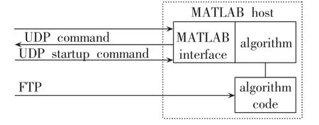
Fig.3 Structure of MATLAB host
1.4 Structure of controller host
The structure of controller host is shown in fig.4.Controller host serves as the master to forward the co-simulation,in particular,it coordinates and synchronizes the simulation steps of each individual simulator,and manages the information exchanged between them.Moreover,centralized control algorithms in power systems can also be implemented in the controller host.As the same as indicated in subsection 1.3,UDP is used to exchange information and transmit the startup command,while FTP is used to update the execution algorithms in controller host.

Fig.4 Structure of controller host
1.5 Structure of OPNET host
OM[19]is a commercially-available simulator for data networks.It supports design and analysis of communication networks,devices,protocols,and applications,with great flexibility.It uses a hierarchical strategy to organize the basic models to construct the system model of a network.OPNET provides mechanisms to interact with other software.In particular,this interaction can be realized through programming in the execution controller embedded in OPNET as shown schematically in fig.5.The SITL(System In The Loop) models from OPNET allows the communication and power simulation network to run jointly in real-time.Each key power network device will be assigned its own IP subnet,which requires the simulated network to route packets among power network devices.Such studies would allow identification of influence of key communication factors,such as protocols,latency and bandwidth requirements,cyber security and data management,on power system.

Fig.5 OPNET internal mechanism to support co-simulation
As illustrated in fig.5,in order to communicate with the external system,the nodes in OPNET must contain an external system module Esys[15].The Esys not only has the function to handle and send out packets,but also has a mechanism which enables it to interact with any external C code in execution controller.It is realized through Esys interfaces,which can be set and read either by the Esys itself or by the external C code in the execution controller embedded in OPNET.Hence the interfaces act as bidirectional channels to transmit information between an OPNET model and the external system.User can define how many interfaces there are and what type each interface is within an Esys,because one Esys interface can only handle one selected data type,such as integer,double,string,pointer,etc.
Simulation models in OM are composed as a hierarchy of objects at three main levels:starting from the bottom,there is the process model that consists of a FSM(Finite State Machine),C code and Proto C functions defining how the process reacts to an event;at the second level is the node model,it is an organized set of modules describing the various functions of each node;at the top of the hierarchical construction is the network model that defines the network layout and characterizes the node attributes for a particular communication scenario.
At the node(second) level,the model of each node contains four parts,or modules,as shown in fig.6.The Esys module is responsible for communication with the external.The process module manages data packet exchanges between the Esys module and other modules of node.Two other modules representing the transmitter and the receiver functions of communication channel are also included.

Fig.6 Node level model
At the process(lowest) level,the model of the Esys contains four parts,as shown in fig.7.To cosimulaiton,the Esys is the most important part.The behavior of the Esys is described in terms of finite state machines.Two states are defined for co-simulation,they are the initial state(icon no.1) and the idle state(icon no.2).Once the OPNET simulator is started,the Esys will shift from initial state to idle state,and remain in idle state during the simulation process unless it is interrupted.Two types of interrupts are defined,which are illustrated in fig.7 as dashed arrows.One is named as ESYS_ARRIVAL(icon no.3),it is triggered by arrival of external data from the execution controller.The otheris named as STRM_ARRIVAL(icon no.4),it is triggered by arrival of internal data packets sent by other modules inside the node.Once the simulation is started in OPNET,the process model will execute in simulation kernel to realize interaction with external simulator.

Fig.7 Process level model
2 Hardware implementation scenario no.1
2.1 Implementation with PC nodes
The scenario no.1 of hardware implementation with PC nodes for the proposed co-simulation platform is shown in fig.8.In this case,both the MATLAB host and controller host are implemented in the PC server,the structure of PC nodes will be detailed in the following subsection.A personal computer is used as OPNET host,where the OM version 14.5 is installed.This platform is especially suitable for simulation of very-large-scale power system with information exchanges.
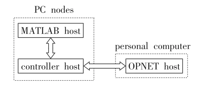
Fig.8 Implementation of proposed co-simulation environment with PC nodes
2.2 Structure of PC nodes
For the purpose of RT(Real-Time) simulation of multi-domain system,a new type of simulator for complex system that leverages on the computational capabilitiesofmulti-processormachinesisunder consideration,for the purpose that the PC nodes are acquired based on shared memory machines.This platform offers the advantage of being a commercial product and thus it can be replicated and expanded easier.The following specifications have been set for this machine:
a.Higher speed and lower latency communi-cation among processors;
b.PCI connections supporting I/O boards to perform HIL(Hardware-In-the-Loop) and PHIL(Power-Hardware-In-the-Loop)tests.
The proper solution that satisfies these specifications is the use of shared memory architecture,but it is very difficult to find such a shared memory machine that is able to manage at least one PCI connection for every eight cores.The solution that adopted is a mixed architecture where each node is based on shared memory structure,so that the information exchange among 16 cores is the fastest because they all read from the same memory.One of the fastest deterministic protocols on the market called infiniband is used.
Each of 16 cores can be assigned as a MATLAB worker,and run the simulation of very-largesystem in parallel through MATLAB DCS.The controller host is also implemented in this PC nodes to coordinate the co-simulation with MATLAB hosts and OPNET host.
3 Hardware implementation scenario no.2
3.1 Implementation with DSP nodes
The scenario no.2 of hardware implementation with DSP nodes for the proposed co-simulation platform is shown in fig.9.In this case,the DSP(Digital Signal Processor) node servers as the MATLAB host,the structure of DSP nodes will be detailed in the following subsection.A Xilinx FPGA(Field Programmable Gate Array) board is used as the controller host to coordinate co-simulation,and a personal computer is used as the OPNET host.Compared with scenario no.1,this platform is suitable for smaller-scale power system and requires less coding effort.

Fig.9 Implementation of proposed co-simulation environment with DSP cluster
3.2 Structure of DSP nodes
For the RT simulation of distributed system,another simulator based on series of DSPs is developed.The main focus of this application is the RT simulation of distributed energy system.
The RT simulation hardware is designed to be a modular and rack-based system.Each rack consists of up to eight processing cards connected via a back-plane.Optionall y,one interfacing card can be added to each processing card to connect custom hardware.The backplane offers communication interfaces to processing cards and to off-rack components.Multiple racks can be combined in one cabinet and even multiple cabinets can be connected to each other for large-scale system.
3.3 C code generation
The code used for algorithm implementation in DSP cluster is generated from MATLAB.MATLAB coder generates standalone C and C ++ code from MATLAB simulation models.The generated source code is portable and readable.MATLAB coder supports a subset of core MATLAB language features,including program control constructs,functions,and matrix operations.It can generate functions that let users accelerate computationally intensive portions of MATLAB code and verify the behavior of generated code.
MATLAB coder works with Simulink coder and embedded coder to generate C code from Simulink models that contain MATLAB code.The generated C code can be used for both RT and non-RT applications:
a.Standalone execution;
b.Integration with other software for rapid prototyping;
c.Accelerating MATLAB algorithms;
d.Embedded implementation,such as hardwarein-the-loop testing.
4 Potential application case studies
One of the potential applications of proposed co-simulation environment is to simulate the control performance in AC microgrids.AC microgrids are attracting more attention because they can lead to more efficient integration of DER(Distributed Energy Resources).The configuration of the investigated AC microgrid is shown in fig.10.It integrates PV(PhotoVoltaic) systems,FC(Fuel Cell),WT(Wind Turbine) generators,ES(Energy Storage),loads,and a main CB(Circuit Breaker).All the energy systems are connected in parallel to a common AC bus line through converters and inverters.
The proposed control architecture consists of a GC (Global Controller ) that o ptimizes the overall process and a distributed number of LCs(Local Controllers) associated with each subsystem in AC microgrid(as shown in fig.10).
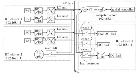
Fig.10 Structure of investigated AC microgrid
LC is responsible for each subsystem inside the microgrid.In LC,polynomial-chaos-theory based method is presented to realize the sensor validation and information rebuilding[20-21],which further guarantees that the measured data is right when control algorithms are applied in AC microgrids.The models of each LC and their associated subsystem are built in each paralleled MATLAB host and the simulation can be run concurrently.
GC coordinates the outputs of the subsystems in order to obtain the optimal efficiency of the whole system.Synergetic control theory,which is based on the ideas of self-organization,is adopted in GC.The theory allows designers to derive analytical control laws for nonlinear,high-dimensional,and multi-connected systems.The synergetic control has the capability to maximize the system efficiency by coordinative control that changes the number of operating converters.The GC control algorithm is implemented in the controller host of proposed cosimulation environment,and the communication dynamics between GC and LCs are simulated in OPNET host with OM.
The model is divided into several targets as shown in fig.10.RT cluster 1 contains the distributed energy sources of WT and PV.RT cluster 2(in this case study,PC cluster is used) contains the main grid source along with FC and ES,while RT cluster 3 contains the vital and non-vital loads.The communication network is composed of the following nodes:the sensing unit(measurement),main CB signal,local controller,load controller,and the server which could function as a global control center.The communication is achieved through a virtual Ethernet network and each node is placed at different distances,obtaining dissimilar delay values for different communication paths and applications(e.g.control,protection,etc.).
When a serious fault occurs at the grid side,the main CB will open and send a signal to the load controller,which will disconnect the noncritical loads.Then,the loads will be connected back to the system one by one.As this process occurs,the DC bus voltage of ES is measured and sent to the switch controller of loads periodically through the virtual network for monitoring.
Within the network,parameters such as latency,bandwidth limitation and packet losses are introduced.Drop of DC bus voltage signifies that there are more loads than the distributed energy sources can sustain,thus,the last load added to the system will be disconnected and the process of reconnecting loads is stopped.The detailed description of the whole process will provided in the following with simulation results.
The influence of the communication network on the model described previously is tested.The details of the power capacity of each unit within the system are shown in fig.10.The distributed energy sources can supply a total power of 11.5 kW,while the non-vital loads and the vital load require 12 kW(4 kW per load) and 1 kW respectively.The normal DC bus voltage is 800 V and its threshold level is 700V(when the bus voltage is lower than this value,the last added load should be disconnected).
The simulation results without delay and with delay are shown in fig.11 and fig.12 respectively.In fig.11 and fig.12,sCBrepresents the CB signal.

Fig.12 Simulation results with communication delay
In the first situation,it assumes no delay during the data transmission,an interruption(three-phase fault) from the grid side occurs at t1,the main CB opens,and all the non-vital loads are disconnected.At t2,the first non-vital load is connected to the system,while the rest ones are attached every 0.1 s afterwards.At t4,switch 3 is closed and the third non-vital load is added.Since at this time the distributed energy resources do not have enough power to supply the load,the DC bus voltage on the LES side begins to drop.When the voltage drops below 700 V,the load last added to the system is re-disconnected in order to allow the DC bus voltage to return to its normal value.
In the second situation,delay,bandwidth,and packet losses are introduced in the virtual communication network.In addition,it displays the importance of combination of power and communication systems modeling for power system.The restoration process is the same as in the first situation.However,two factors are visible due to the delay introduced by the network.
a.At time t1,there is a larger disturbance when the main CB is disconnected,and the actual voltage measured on the DC bus drops below the threshold voltage.This is due to the communication delay (6ms)between the main CB and the load controller.
b.At time t4,a bigger drop in voltage UDCbelow the threshold value occurs due to the communication delay(23 ms) between the ES and the load controller.As can be noticed,there are also bigger disturbances in the AC bus voltage and the output current of ES.
The simulation step of the proposed distributed co-simulation platform can reach ms level,or even μslevel,which guarantees RT execution of the simulation model,while the traditional co-simulation platforms will normally cost more than 20 min even when simulating a small-scale system[15,22-28].Moreover,the distributed simulation will not change the correctness of the simulation results as verified in literature[5]with discrete event system specification.
5 Conclusion
Although co-simulations have become popular solutions for jointly analysis of power and communication in modern power systems,they are facing challenges,such as the relatively longer executing time.For this concern,this paper presented a distributed co-simulation platform which utilizes MATLAB PCT and DCS software to obtain shorter executing time.The distributed co-simulation environment consists of four parts:a graphical user interface to start and stop the simulation,MATLAB workstations to simulate the power systems,a controller host to coordinate the co-simulation time and information exchange,and an OPNET host to simulate the communication dynamics.Each part is elaborated in detailed in this paper,and two hardware platforms are built in laboratory to implement the proposed method.Moreover,control of AC microgrid is proposed as a potential application case study of this distributed co-simulation environment,and preliminary simulation results demonstrate the effectiveness of combined simulation of power and communication.
