Design and implementation of multi-hop video transmission experiment system in VANET
2014-09-06MohamedMohsenXuKaikaiLiuChengyiShenLianfeng
Mohamed Mohsen Xu Kaikai Liu Chengyi Shen Lianfeng
(National Mobile Communications Research Laboratory, Southeast University, Nanjing 210096, China)
Design and implementation of multi-hop video transmission experiment system in VANET
Mohamed Mohsen Xu Kaikai Liu Chengyi Shen Lianfeng
(National Mobile Communications Research Laboratory, Southeast University, Nanjing 210096, China)
A wireless multi-hop video transmission experiment system is designed and implemented for vehicular ad-hoc networks (VANET) and the transmission control protocol and routing protocol are proposed. This system integrates the embedded Linux system with an ARM kernel and consists of a S3C6410 main control module, a wireless local area network(WLAN) card, a LCD screen and so on. In the scenario of a wireless multi-hop video transmission, both the H.264 and JPEG are used and their performances, such as the compression rate, delay and frame loss rate, are analyzed in theory and compared in the experiment. The system is tested in the real indoor and outdoor environment. The results show that the scheme of the multi-hop video transmission experiment system can be applicable for VANET and multiple scenes, and the transmission control protocol and routing protocol proposed can achieve real-time transmission and meet multi-hop requirements.
vehicular ad-hoc networks (VANET);embedded Linux;multi-hop video transmission;H.264;real-time property
With the rapid development of vehicular ad-hoc networks (VANET) research, multimedia transmission among vehicles is becoming more and more important among people’s requirements[1-2]. They are not just satisfied with transmitting short messages such as vehicle position, road conditions and warning messages, video entertainment or video conference will be required in the future.
The video signal of the multimedia transmission system involves many technical fields[3-4]. It can be used in many application fields besides VANET such as video monitoring in factories or on highways.
There are two important requirements for the multi-hop video transmission system to which should be paid much attention[5]. The first one is its real-time property. Sometimes this is the most important factor, especially in military activities. The second one is its multi-hop character. VANET is usually a large network, and the vehicles that want to transmit video data may be located far away from their communication range, thus they need the help of other vehicles to forward the data. This situation can also occur in video monitoring systems while the video capturing part is far away from the monitoring part.
Addressing this issue, a testing system of wireless multi-hop video transmission system applied to VANET has been designed, which uses the efficient transmission control method, wireless local area network card (WLAN) communication technology, optimized H.264 digital video encoding, the decoding algorithm and some other technologies.
1 System Description
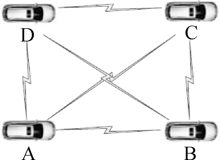
The system application scenario of the wireless multi-hop video transmission system is shown in Fig.1. Every vehicle in VANET is equipped with a communication device, through which they can transmit information to other vehicles within their communication range. In this paper, the following assumption has been made that every vehicle is equipped with a camera which can capture pictures or videos. There should also be an LCD screen on which the video received can be shown.
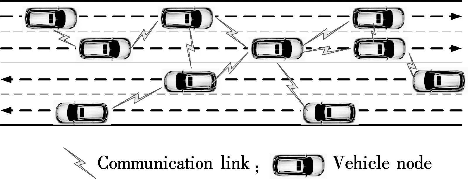
Fig.1 Scenario of wireless multi-hop video transmission system
Although 4G technology or satellites are used to transmit video data to vehicles in VANET, the bandwidth of these technologies are narrow and the cost is high. So the WLAN has been selected to achieve this purpose. However, the WLAN also has its shortcomings, and its communication range is limited. If the destination vehicle is within the source vehicle’s communication range, they can transmit video data directly. Otherwise they may need the help of other vehicles which are located between them to form a transmission link to forward the data.
Like many other wireless video transmission systems, latency is a very important factor that should be taken into account in this system. Latency can be generated during many procedures, i.e., video encoding, video decoding and data transmission. Some measures are taken to reduce latency and they will be discussed in the following sections.
There are several different modules in the wireless multi-hop video transmission system and each of them has different functions. They can be separated into the transmitting part and the receiving part, as shown in Fig.2.
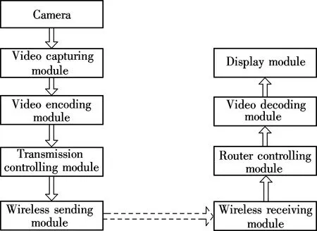
Fig.2 Module diagram of multi-hop video transmission system
The transmitting part is shown in the left part of Fig.2. This part contains five modules: a camera, a video capturing module, a video data encoding module, a transmission controlling module and a wireless sending module.
The receiving part is shown in the right part of Fig.2. This part includes four modules: a wireless receiving module, a router controlling module, a video decoding module and a display module. The router controlling module will check the destination address immediately after the receiving module receives the data. If it is the destination of this frame, it will deliver the data to the decoding module, otherwise it will judge whether it should forward the message to the destination vehicle via some routing information. The receiving part will send the receiving data to the wireless channel without processing it again, if necessary.
2 System Design and Implementation
2.1 Hardware architecture
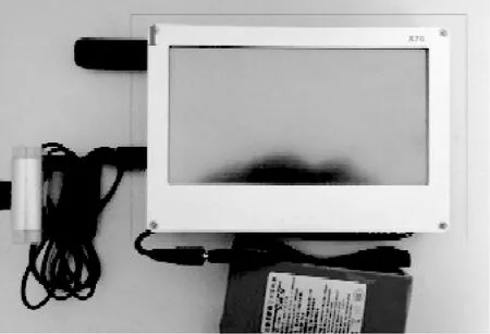
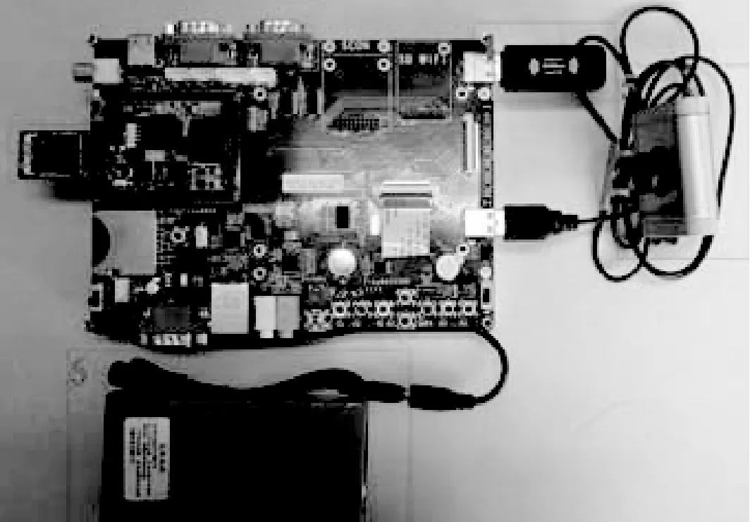
The hardware architecture of the terminal of this system is presented in Fig.3. The terminal is based on the ARM core11 architecture and Samsung’s S3C6410 is chosen as the main chip. External memories use DDR SDRAM (256 MB) and NAND FALSH (2 GB). In this terminal, the camera and the WLAN module are connected with S3C6410 through USB interface. A touch LCD screen is also used to show the video.
Samsung S3C6410 adopts the 64/32 bit internal bus architecture. It includes many powerful hardware accelerators such as motion video processing, audio processing,and so on. It also has an integrated multi format codec (MFC) which supports the encoding and decoding of MPEG4/H.263/H.264. Samsung S3C6410 is based on ARM1176JZF-S core, and its main frequency is 667 MHz, including single instruction multiple data (SIMD) for media processing[6]. These allow it to meet the requirements of the system.
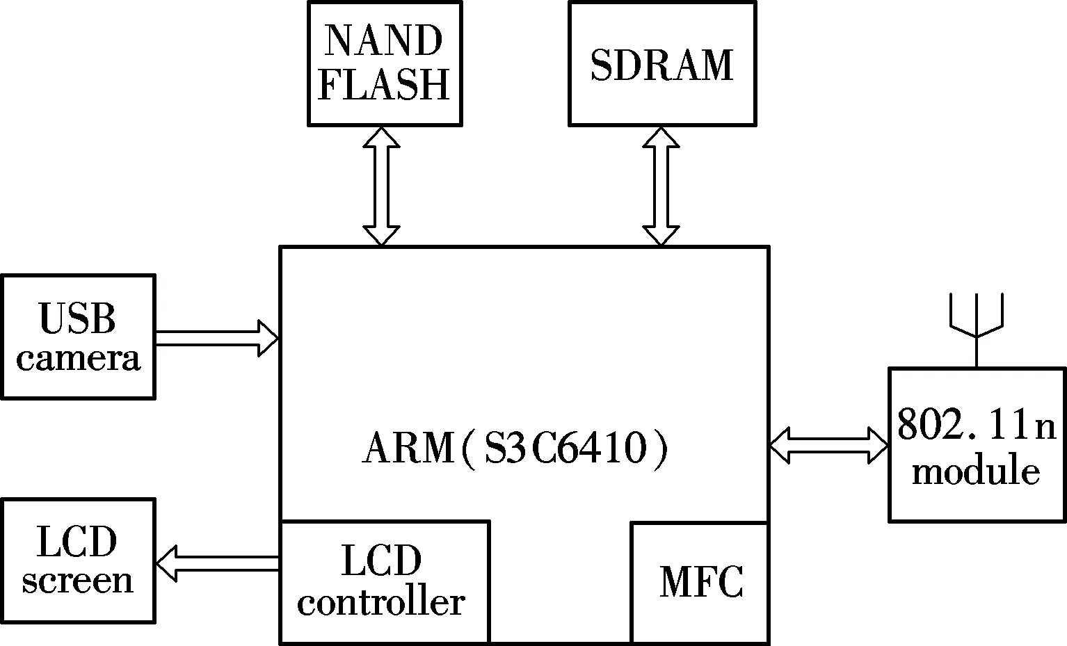
Fig.3 Hardware architecture of multi-hop video transmission system
The Eloam 582 USB camera is used. It adopts Vimicro USB2.0 control chips and supports UVC (USB video device class) function. Its maximum resolution can support 800×600 pixels while the frame rate reaches 30 frames/s. Moreover, it can capture pictures or videos in the format of RGB24, YUV.
The netcore NW362 WLAN card is used as the wireless module of this system. It has two antennas in both the transmitter and receiver parts, so its transmission rate can reach 300 Mbit/s while using this MIMO system. It satisfies the IEEE 802.11n standard and it is also compatible with the IEEE 802.1lb/g standard. It can work in infrastructure mode, Ad Hoc mode and AP mode, which makes it suitable for this system.
2.2 Software architecture
2.2.1 Methods of reducing latency
Latency is an important target in the video transmission system. To reduce latency and ensure real-time capability, the following are considered.
1) Encoding format. The encoding format of the video data is very important due to the fact that a better encoding format can reduce delay and help improve the performance of the system. Compared with other existing encoding formats, H.264 standard has the best performance in video transmission[7-8]. For example, it has a high compression rate, which is double that of MPEG-2 and 1.5 to 2 times that of MPEG-4 and it can provide bit-rate reductions up to 50% for the equivalent perceptual quality compared to its predecessors. H.264 defines different profiles and levels. Each profile and level specifies restrictions on bit streams, and hence the limits on the capabilities needed to decode these bit streams. They offer incremental level capabilities, which alleviate the constraints on them[9]. All these characters make H.264 suitable for video transmission over the wireless network.
Compared with software codec, hardware codec can dramatically reduce the time cost for encoding or decoding[10]. So S3C6410 which has an integrated MFC that can support the hardware codec of H.264 has been chosen as the core of this system.
2) Transport protocol. This wireless video transmission was developed on the client/server model and the transmission protocol is real time transport protocol (RTP). RTP is a transport protocol aimed at the multimedia data stream on the Internet and it is designed to provide time information and achieve stream synchronization[11]. RTP can be established on TCP, UDP and all the other protocols. However, TCP uses a three-way handshake which can incur relatively long delays, so RTP is adopted in this experimental system. Real time transport control protocol (RTCP) is also used to provide a reliable transmission mechanism for data in order, flow control and congestion control.
3) A relatively large bandwidth. The wireless channel bandwidth also affects transmission delay since the video data size is very large. In order to lower the transmission delay, IEEE 802.11n specification is chosen as the wireless transmission standard of this system.
By means of the orthogonal frequency division multiplexing (OFDM) and the multiple input and multiple output (MIMO) techniques[12], IEEE 802.11n can reach a transmission speed of up to 300 Mbit/s, which is sufficient for this system.
Fig.4 shows a software protocol stack from the top-level application layer to the underlying physical layer. As shown in Fig.4, first, the transplant Linux kernel should be transplanted into S3C6410 and the chosen version is Linux 2.6.36. Then, some drivers of the devices which are used in the system can be transplanted, such as a USB camera, a USB WLAN card and so on. RTP/RTCP chooses open source JRTPLIB with an installed version of JRTPLIB3.7.1. The RTP data transfer protocol manages the delivery of the real-time data. The RTCP provides reception quality feedback, participant identification and synchronization between media streams. RTCP runs alongside RTP, providing periodic reporting of this infor-mation. UDP is also used in this system. As to the WLAN part, IEEE 802.11n protocol is used.
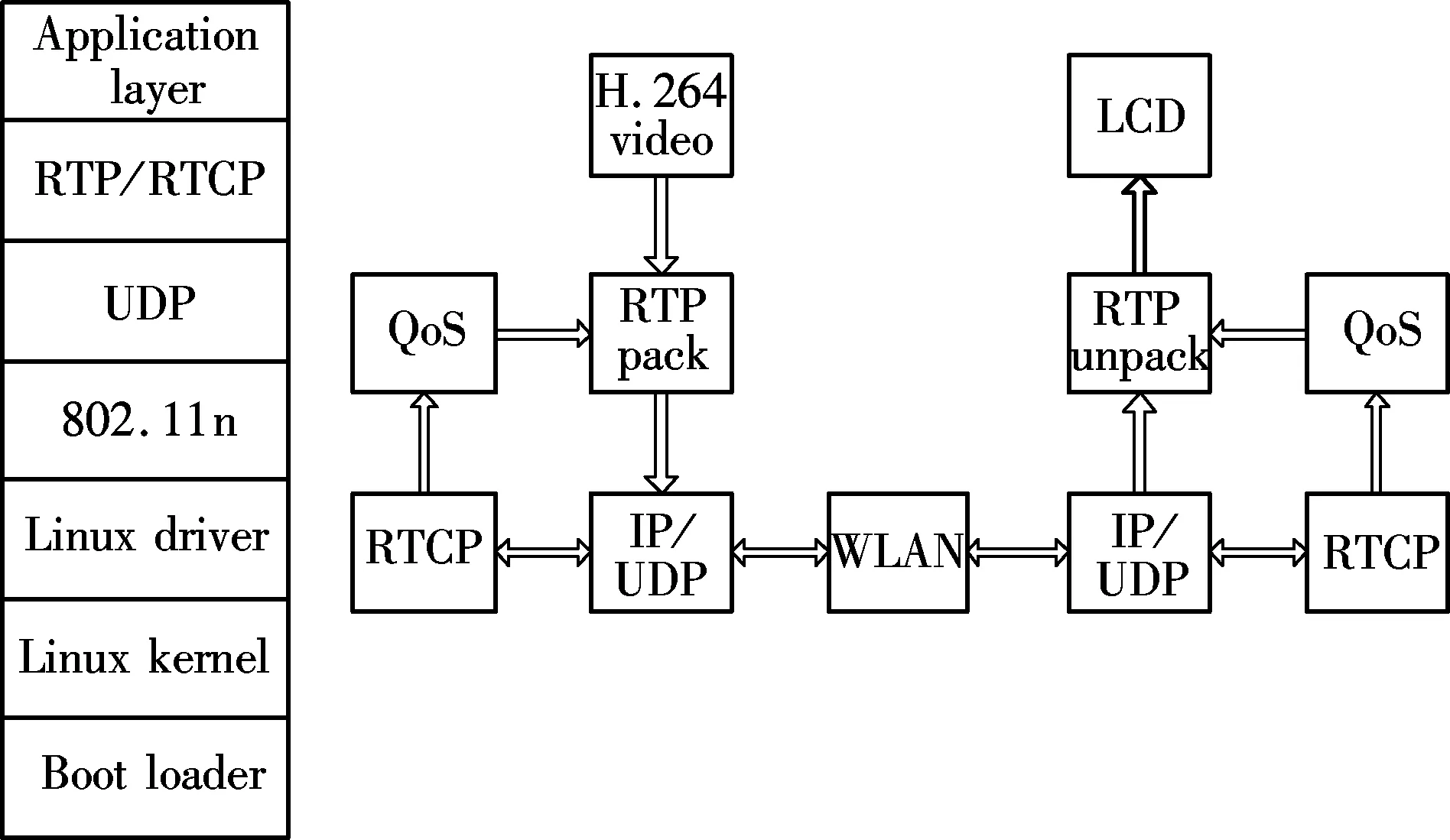
Fig.4 Software architecture of multi-hop video transmission system
2.2.2 Methods of multi-hop
To stream a video across multiple hops, a multi-hop path between the transmitter and the receiver has to be found. A routing protocol is therefore required to establish and manage connectivity within VANET.
A routing protocol may form various topologies depending on the selected metrics and quality of service (QoS) requirements. The peer-to-peer video streaming application relies on a network layer routing protocol to carry out the routing tasks[13]. There are various types of routing protocols in VANET. For example, in city and highway scenarios there are many infrastructures that can help forwarding messages while in a desert scenario there is no such benefit. The density of vehicles in VANET also has an influence on routing algorithms. By now, all the studies are theoretical, so in the experimental system some existing routing protocols should first be used when forwarding video data in this paper. In the future, it can be changed to a specific routing protocol in different scenarios.
There are already some protocol stacks in the Linux kernel such as ad hoc on-demand distance vector routing (AODV), dynamic source routing (DSR) and so on. Among them, DSR protocol has been chosen. DSR is a simple and efficient routing protocol designed specifically to be used in multi-hop wireless ad hoc networks of mobile nodes. DSR allows the network to be completely self-organizing and self-configuring, without the need for any existing network infrastructure or administration[14]. The protocol used in this system is dsr-uu-0.2. When each device starts working, the USB WLAN card working on AP mode should also be configured so that they can forward data to others.
2.2.3 Software flowchart
The flowchart of the sending process is shown in Fig.5. There are three parts in this process: the video capture process, data compressing and the encoding process and RTP sending process.
Video for Linux two (V4L2) is used in the Linux kernel to control the video capturing process. The working process is shown in Fig.5(a). There are two important system commands for V4L2 during video capturing: ioctl() and mmap(). ioctl() can control I/O channels of equipment, set parameters of videos and frames, and can also investigate current device properties. Main ioctl commands are shown in Tab.1. mmap() is used when sharing memory between processes. It uses memory map technology. After a general file is mapped to the address space of process, the file can be accessed by processes similar to ordinary memory, that is, the memory can be read and written directly[15]. By using a memory map, all the data will not be copied, so the capture time is reduced and the efficiency is improved.
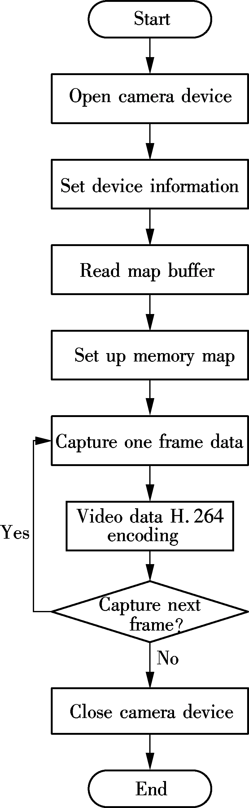
(a)
(b)

(c)
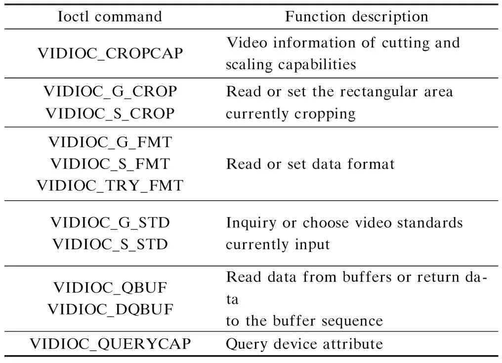
Tab.1 Mian iotcl commands
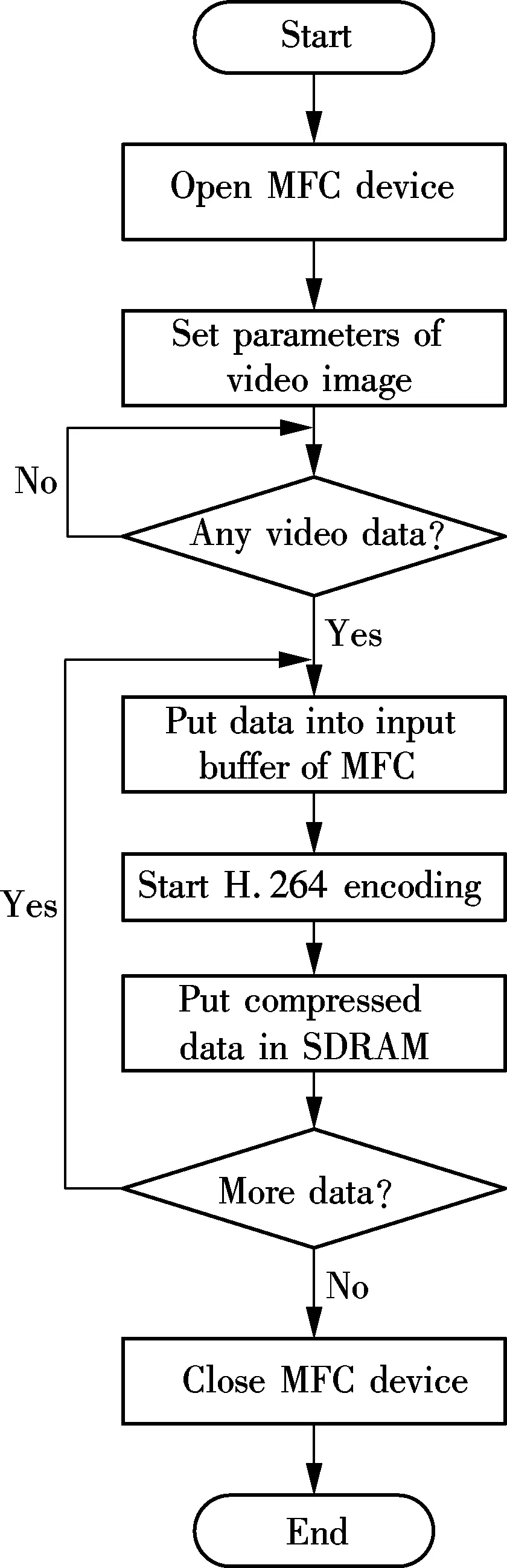
For the implementation of high-resolution video transmission, video compression technology is a key component. As discussed above, H.264 is used as compression format in this system and S3C6410 has an MFC that consists of an embedded bit stream processor and a video codec module. After loading the MFC drive, functions can be called to encode the video data.
So when initiating the sending process, the MFC driver of H.264 compression is opened and the specific parameters of the video image are set, including size, frame rate and so on. After the camera has captured the video data in the memory, the process puts the data into the input buffer of MFC and calls the MFC function to start H.264 compressing. When the encoding is done, all the data is put in the SDRAM for the RTP process to send. This process is shown in Fig.5(b).
The RTP sending process is shown in Fig.5(c). Processor S3C6410 checks whether there are frames to be sent in SDRAM. If this is so, S3C6410 will create an RTP process for sending. Meanwhile, it also creates necessary feedback information based on RTCP. Then the sending process sets the address and port. If sending fails, the packet will be enveloped and sent again. The sending process does not stop until all frames have been sent.
Since the DSR protocol is used when building a communication link between the source and its destination, each device will check the destination address of the message received. If it is not in the link, it will delete the message; otherwise it will forward the message to the next hop without any processing. When the destination device receives the message, it will call the RTP unpacking process and then put the data into the buffer of the MFC, as shown in Fig.4. MFC is used to decode the video data. After that, all data is delivered to the LCD controller and shown on the LCD screen.
3 Analysis of System Performance
To obtain the time difference between the transmitter and the receiver, a method is proposed as shown in Fig.6. First, the on-board unit A connects with the reference PC and then the reference PC sends data to on-board unit A. It carries out the same operation on on-board unit B.
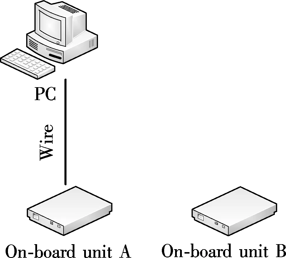
Fig.6 Sketch map of obtaining time difference between on-board units
The variable ΔtA,which represents the time difference between the PC and on-board unit A, can be written as
(1)

The variable ΔtB, which represents the time difference between the PC and on-board unit B, can also be written as
(2)

Thus, the difference value between ΔtAand ΔtBcan be formulated as follows:

(3)
Due to the small size of data, the time difference of transmission and processing is relatively small. The calculated value in Eq.(3) can be approximately equal to the difference value between the local time values of on-board unit A and on-board unit B.
4 Experimental Results
The physical map of the wireless multi-hop video transmission is shown in Fig.7. After the implementation of this experimental system, it can be tested in the indoor and the outdoor environment[16]. A dual trace oscilloscope Agilent MSO6054A is used to test the delay time of the video transmission system.
(a)
(b)
The index of each module in Fig.7 can be expressed as follows: 1) The LCD screen is the module which can display the video and the routing list data; 2) Main control model, S3C6410; 3) OV9650 CMOS camera model; 4) IEEE 802.11n USB WLAN card; 5) ZC301 USB camera; 6) 5 V 2 A battery.
4.1 In the indoor environment
The proposed system will be tested in the indoor environment. The test scene is set as shown in Fig.8 and then the system will be measured in the near distance scenario. The main parameters are the system throughput and the transmission delay. In the indoor environment, some IPs can be shielded to simulate a multi-hop scene. The IPs of on-board unit A, on-board unit B, on-board unit C and on-board unit D are set to be 192.168.2.2, 192.168.2.3, 192.168.2.4 and 192.168.2.5, respectively.
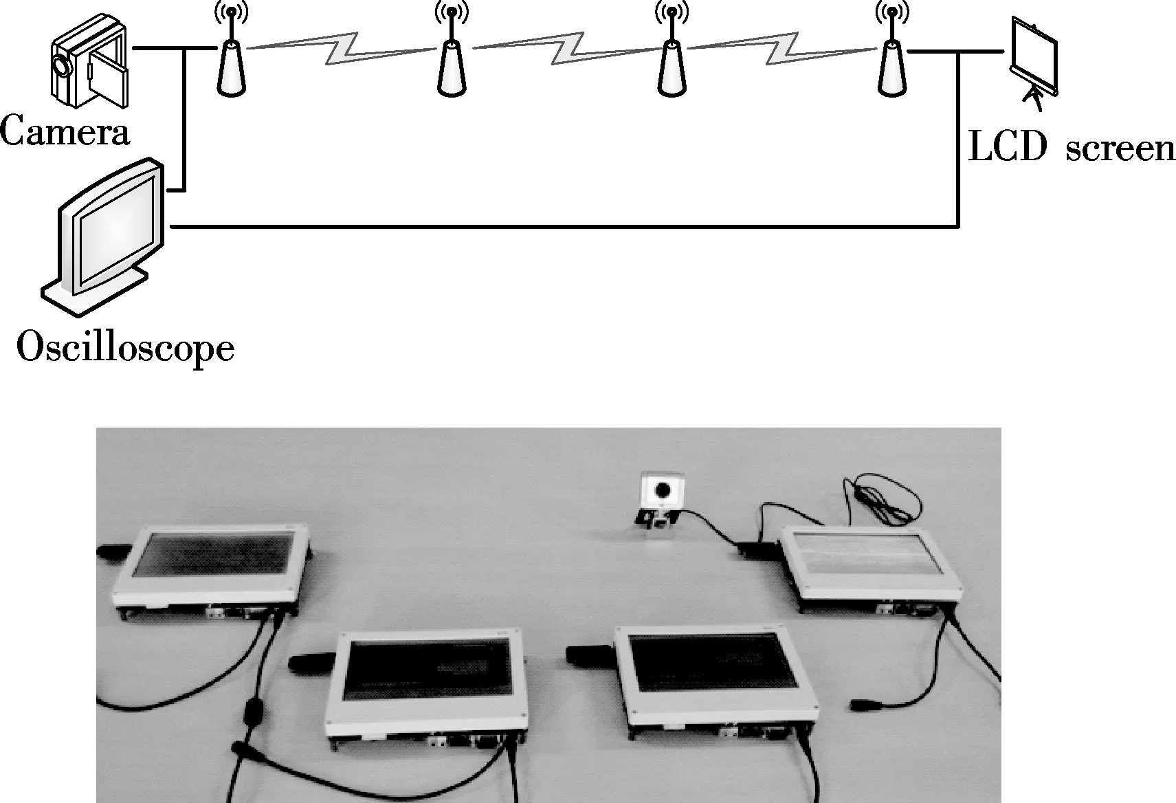
Fig.8 Test system model
First, the compression ratios of JPEG encoding and H.264 encoding are tested on the video data. The order in the Linux system ifconfig can display the data statistics. The video data on the transmitter also can be obtained by using the same order. Thus, the compression ratios of JPEG encoding and H.264 encoding can be calculated. In this test, the frame rate of USB camera and OV9650 camera are set as 10 frame/s. The height and width of video is 320 and 240 pixels, respectively.
Broadcast routing information also can be obtained by the order ifconfig. However, compared with the video data, the routing information is very small. Thus, it can be concluded that the video compression ratio of H.264 is much higher than that of the other.
Then, the delay of the proposed system will be tested. To obtain the video transmission delay, the difference value between the transmitter and the receiver should be calculated. In this test, on-board unit D and on-board unit B are set as the transmitter and the receiver, respectively. The result is shown in Tab.2. The local time difference values between on-board unit D and PC and between on-board unit B and PC are -319 and 10 747 ms, respectively. Thus, the local time difference value between on-board unit D and on-board unit B is 11 066 ms.
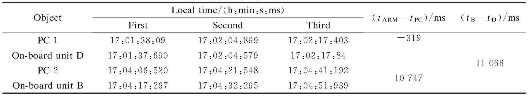
Tab.2 The time difference value between on-board unit D and on-board unit B
Based on the above result, the measured values are averaged to obtain the video transmission delay between on-board unit D and on-board unit B with different network environments. The result is shown in Tab.3.

Tab.3 The video transmission delay between on-board unit D and on-board unit B
It can be seen that although the data volume of H.264 is small, the transmission delay in one hop is larger than that of the JPEG. This can be explained by the fact that the data gathered by the USB camera has been compressed. Thus it can be transmitted directly. However, the data gathered by OV9650 camera should be encoded before being transmitted. In the multi-hop scene, the video transmission delay of H.264 becomes smaller than that of JPEG. The reason is that due to the small size data volume, the required time in transmission, reception and copy of H.264 on the relay nodes become small. Therefore, the larger the multi-hop number is, the greater advantage H.264 appears to have.
4.2 In the static outdoor environment
In this subsection, the system will be tested in the static outdoor environment. Besides the parameters in the indoor environment, the frame loss rate (FLR) is also measured in the outdoor environment.
The influence of distances to one-hop video transmission is measured to obtain the valid distance of one-hop transmission. The result is shown in Tab.4.
From Tab.4, it can be found that when the distance between the transmitter and the receiver reaches up to 50 m, the transmission delay and FLR have already been too high due to the limited transmission power of the network card. So, in this test, the one-hop transmission distance is set to be less than 50 m. Based on the above distance setting, multi-hop transmission will be tested in the outdoor environment.

Tab.4 The transmission delays on different distances
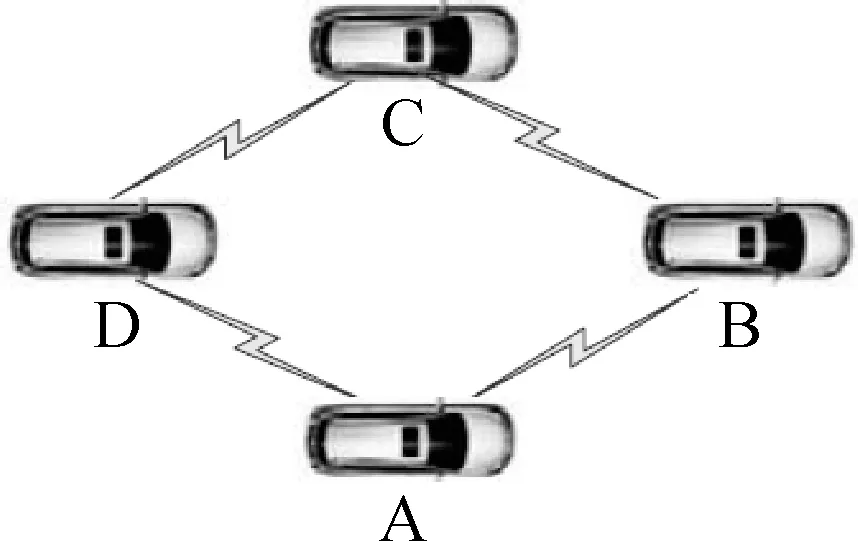
There are three topological structures researched in the multi-hop model, as shown in Fig.9.
(a)
(c)

(b)
The topological structure of the one-hop transmission can be defined. As shown in Fig.9(a), the distance between two adjacent nodes is 40 m and any two of them can communicate with each other directly. Thus, the communication type in this topological is one hop. The result is that the video transmission delay is 263 ms and the FLR is 17%.
The topological structure of a two-hop transmission can be defined. As shown in Fig.9(b), A and C can communicate with B and D in one-hop transmission type. However, A and C or B and D cannot communicate with each other directly except by the two-hop type. D and B are set as the video transmitter and receiver, respectively. It can be found that through two-hop transmission, the video transmission delay is 347 ms and the FLR is 18%.
The topological structure of a three-hop transmission is shown in Fig.9(c). A is set as the transmitter, D is set as the receiver and B and C are the relay nodes. Thus, the transmission type is three hops. It can be found that the video transmission delay is 429 ms and the FLR is 21%.
4.3 In the dynamic outdoor environment
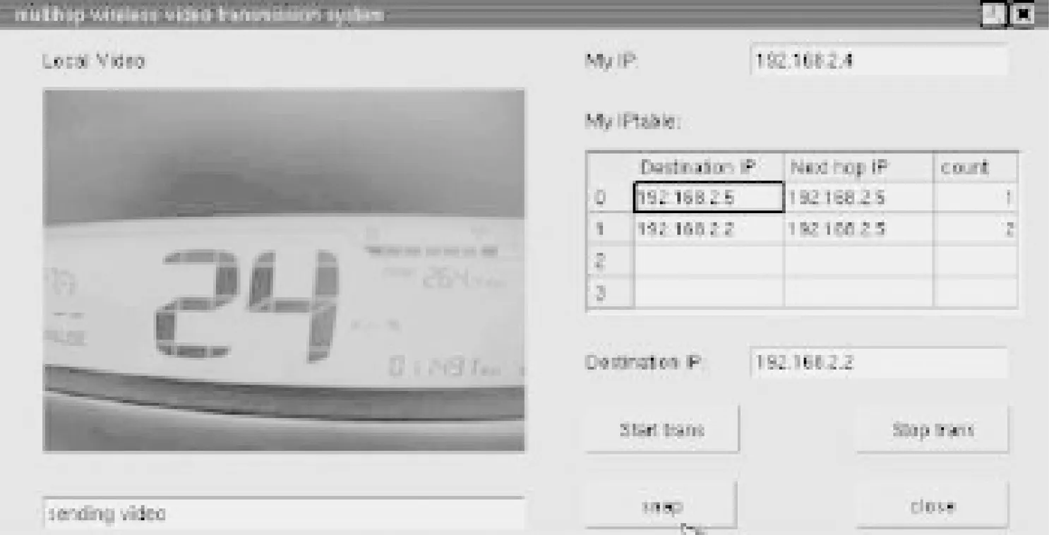
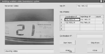
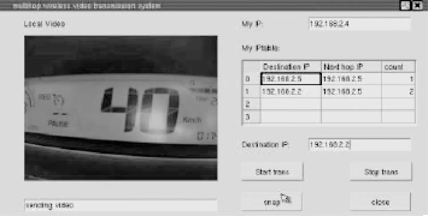
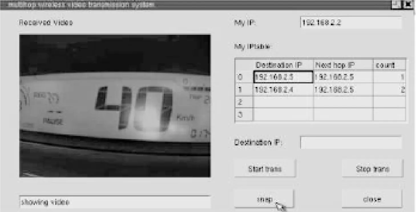
The experimental system in this paper is configured using three cars and the performance is tested when the cars are moving towards the same direction. The distance between two adjacent cars is 30 m. Thus, the type of two-hop transmission is considered here. The screenshots of the transmitter and the receiver in different velocities can be seen in Fig.10.
(a)
(c)
(c)
(d)
Fig.10 Screenshots of the transmitter and the receiver at different velocities. (a) Video transmitter ended withv≈20 km/h; (b) Video receiver ended withv≈20 km/h; (c) Video transmitter ended withv≈40 km/h; (d) Video receiver ended withv≈40 km/h
First, the velocity of cars is set to be 20 km/h and each end of the motorcade is set as the video transmitter or receiver. The middle car is set as the relay node. It can be found that through multi-measurements, the average video transmission delay is 293 ms and the FLR is 28%.
Secondly, the velocity of cars is set to be 40 km/h. It can be found through multi-measurement that the average video transmission delay is 317 ms and the FLR is 35%.
Through sufficient testing, it can be concluded that the performance in the static outdoor environment degrades with the increase of the hop number and the performance while in the dynamic outdoor environment, it degrades with the increase in velocity. It can also be seen that in the dynamic outdoor environment, performance degrades more clearly than that in the static one.
5 Conclusion
In this paper a scheme of the experimental system is provided for the wireless multi-hop video transmission in VANET. Hardware video codec is used and many other measures are brought to achieve real-time transmission and multi-hop requirements. The system is tested indoors, the static and the dynamic outdoor environments, respectively.
The fields of multi-hop wireless video transmission technology and video transmission in VANET are rapidly growing and changing, and more study will still be needed, such as that on the interference when there are several video streams transmitting at the same time, and how to transmit video when vehicles are moving quickly. These are all the areas for conducting research in the future.
[1]Asefi M, Mark J, Shen X. An application-centric inter-vehicle routing protocol for video streaming over multi-hop urban VANETs [C]//IEEEInternationalConferenceonCommunications. Kyoto, Japan, 2011: 5962635-1-5962635-5.
[2]Sou S, Shieh W, Lee Y. A video frame exchange protocol with selfishness detection mechanism under sparse infrastructure-based deployment in VANET [C]//IEEE7thInternationalConferenceonWirelessandMobileComputing,NetworkingandCommunications. Shanghai, China, 2011: 498-504.
[3]Asefi M, Céspedes S, Shen X,et al. A seamless quality-driven multi-hop data delivery scheme for video streaming in urban VANET scenarios [C]//IEEEInternationalConferenceonCommunications. Kyoto, Japan, 2011: 5962785-1-5962785-5.
[4]Fan B, Shen L, Song T. The design and implementation of a wireless real-time video transmission system over WLAN [C]//InternationalConferenceonInformationScienceandEngineering. Nanjing, China, 2009: 684-687.
[5]Zhou J, Ye X. Design and implementation of embedded video terminal based on Z228 [C]//2008InternationalConferenceonAudio,LanguageandImageProcessing. Shanghai, China, 2008: 829-833.
[6]Zhu F, Yang M. Design of remote video acquisition system based on 3G [C]//InternationalConferenceonMultimediaTechnology. Hangzhou, China, 2011: 4909-4912.
[7]Zhang M, Sun X, Guan X, et al. Research and application of wireless video transmission system based on H.264 in aluminum production monitoring [C]//InternationalConferenceonMeasuringTechnologyandMechatronicsAutomation. Changsha, China, 2010: 1027-1030.
[8]Meng L, LI J, Ni Y. Design and implementation of wireless video transmission system [C]//InternationalConferenceonMultimediaTechnology. Ningbo, China, 2010: 5631382-1-5631382-5.
[9]Panayides A, Pattichis M, Pattichis C, et al. A tutorial for emerging wireless medical video transmission systems [J].IEEEAntennasandPropagationMagazine, 2011, 53(2): 202-213.
[10]Setton E, Noh J, Girod B. Low latency video streaming over peer to peer networks [C]//IEEEInternationalConferenceonMultimediaandExpo. Toronto, Canada, 2006: 569-572.
[11]Zhuo W, Yang M. An RTP packing technology for wireless transmission of high resolution video [J].ComputerApplicationsandSoftware, 2010, 27(1):218-220.
[12]Li Z, Liang Q, Wang W, et al. Capacity optimization of ultra-wide band system under the coexistence with IEEE 802.11n [C]//InternationalSymposiumonCommunicationsandInformationTechnologies. Hangzhou, China, 2011:553-557.
[13]Hu P, Symons N, Indulska J, et al. Share your view: wireless multi-hop video streaming using Android phones [C]//IEEEInternationalConferenceonPervasiveComputingandCommunicationsWorkshops. Lugano, Switzerland, 2012:782-787.
[14]Jia K, Wu M, Xu C, et al. Enhanced ad hoc network platform based on embeded Arm-Linux [C]//InternationalConferenceonElectronics,CommunicationsandControl. Ningbo, China, 2011: 1448-1451.
[15]Lu Y, Yu H, Zhang P. The implementation of embedded image acquisition based on V4L2 [C]//InternationalConferenceonElectronics,CommunicationsandControl. Ningbo, China, 2011: 549-552.
[16]Xu Kaikai. Design and implementation of wireless video multi-hop transmission system in VANET [D]. Nanjing: School of Information Science and Engineering, Southeast University, 2013.(in Chinese)
一种车联网多跳视频传输实验系统的设计与实现
默罕莫德·默森 许凯凯 刘诚毅 沈连丰
(东南大学移动通信国家重点实验室,南京210096)
提出一种在车辆自组织网络(VANET)中应用的无线多跳视频传输实验系统的设计和实现方案及其对应的传输控制和路由选择协议.该系统将嵌入式Linux与IEEE 802.11n传输协议集成到ARM内核,由S3C6410主控模块、无线局域网网卡及LCD屏等构成.针对VANET的无线多跳视频传输场景,对视频编译码分别采用H.264和JPEG两种标准实现并对它们的压缩比、时延、传输丢包率等性能进行了理论分析和实验比较,进行了室内室外多种不同场景的实际测试.结果表明:所设计的多跳视频传输实验系统方案能够适应VANET等多种场景的应用,所提出的传输控制和路由选择协议能够保证视频传输的多跳和实时性要求.
车辆自组织网络;嵌入式Linux;多跳视频传输;H.264;实时特性
TN915
Received 2014-04-28.
Biographies:Mohamed Mohsen (1974—), male, graduate; Shen Lianfeng (corresponding author), male, professor, lfshen@seu.edu.cn.
s:The National Natural Science Foundation of China (No.61201175, 61171081), Transformation Program of Science and Technology Achievements of Jiangsu Province (No.BA2010023).
:Mohamed Mohsen, Xu Kaikai, Liu Chengyi, et al.Design and implementation of multi-hop video transmission experiment system in VANET[J].Journal of Southeast University (English Edition),2014,30(4):403-410.
10.3969/j.issn.1004-7985.2014.04.001
10.3969/j.issn.1003-7985.2014.04.001
猜你喜欢
杂志排行

Journal of Southeast University(English Edition)的其它文章
- Improved design of reconfigurable frequency response masking filters based on second-order cone programming
- Experimental study on thermal characteristicsof a double skin façade building
- Gene expression profile in H4IIE rat hepatoma cells exposed to an antifouling booster biocide Irgarol-1051 degradation product
- Synthesis and application of an environmentallyfriendly antiscalant in industrial cooling systems
- L(1,2)-edge-labeling for necklaces
- Measurement of spatiotemporal characteristics of femtosecond laser pulses by a modified single-shot autocorrelation