Kinematics analysis of cleaning robot for aircraft surfaces based on screw theory*
2014-09-05YuyangJINMingluZHANGQingjiGAOChangjuanYU
Yu-yang JIN,Ming-lu ZHANG,Qing-ji GAO,Chang-juan YU
1School of Mechanical Engineering,Hebei University of Technology,Tianjin 300130,China;2Robotics Institute,Civil Aviation University of China,Tianjin 300300,China
金玉阳†1,2,张明路1,高庆吉2,于常娟1
1河北工业大学 机械工程学院,天津 300130;2中国民航大学 机器人研究所,天津 300300
Kinematicsanalysisofcleaningrobotforaircraftsurfacesbasedonscrewtheory*
Yu-yang JIN†1,2,Ming-lu ZHANG1,Qing-ji GAO2,Chang-juan YU1
1SchoolofMechanicalEngineering,HebeiUniversityofTechnology,Tianjin300130,China;2RoboticsInstitute,CivilAviationUniversityofChina,Tianjin300300,China
Focusing on 5-DOF cleaning robot for aircraft surfaces,the screw theory and exponentials formula are used for the forward kinematics solution of robot.And the configuration of the end-effector relative to inertial coordinate frame was obtained.Besides,Jacobian matrix of forward kinematics is obtained by the twists,which establishes a basis of singularity of mechanism,future real-time control,and manipulability.
Robot,Jacobian,Kinematics,Screw theory,Exponential formula
1.Introduction
D-H method and screw theory method are used to solve the kinematics for a robot.D-H method is relatively mature and wildly used in analysis of kinematics for robots.The screw theory method only needs to build two coordinate frames,which has a clear geometric meaning.Literature[1] presented a kinematics parameter calibration method for serial robots based on the product of exponential (POE) formula.A linearized model describing the relationship between the errors in the end-effector and the errors in the joint twists,and in the zero position twist is obtained by differentiating the kinematics equation.Literature[2] gave the result of inverse kinematics by using the combined method of algebraic elimination method and Paden-Kahan sub-problem method.
Jacobian matrix relates to static analysis,speed control,and operation[3].The domestic research of the robot Jacobian matrix in recent years is as follows.Literature[4] used differential transform and vector multiplication method to solve the Jacobian matrix.Literature[5] calculated the characteristics of the rehabilitation robot’s Jacobian matrix of the robot by using screw theory.This paper built kinematics and Jacobian matrix by applying screw theory.
2.The construction of kinematics coordinates for aircraft cleaning robot
Through the analysis of working environment and working process for aircraft surface cleaning robot,mechanism should have large workspace and high stiffness.Therefore,the robot should have the optimal workspace,dexterity and obstacle avoidance space to meet targets during operation.According to the functional requirements of cleaning aircraft,the five degree of freedom robot consists of four rotary joint and a prismatic joint,as shown in Figure 1.

Figure 1.Aircraft cleaning robot in its reference configuration
3.The solution to kinematics of the cleaning robot
The essence of serial robot is spatial kinematic chain composed of links with the joint connection.D-H method and screw theory method are usually used to solve the kinematics for a robot.The D-H method described configuration between each link by link frame.N-DOF serial robot requires a total ofn+1 link frame.But screw theory does not need to establish the adjacent link frame.Exponential formula only needs two coordinate frames,the base frame{S},and the tool frame {T} attached to the end-effecter of robot.As shown in Figure 1,the base frame{S} is attached to a point on the cleaning manipulator which is stationary with respect to link 0.All of vectors and points are specified relative to the base frame {S}.All joint angles are defined by right-handed coordinate system,the angle about along direction of the axis is positive if it represents a clockwise rotation as viewed along the direction of the axis.


(1)

(2)

where
e24=(l1+θ3)(1-cosθ5)-sinθ5(l0+l2)
e34=(l1+θ3)sinθ5+(l0+l2)(1-cosθ5)
4) If we definegli-1li(θi) as the transformation between the adjacent link frames,then combining the individual joint motions,the forward kinematics map of manipulator has the form:
(3)
gst(0) is the rigid body transformation between {T} and {S} when the clean manipulator is in its reference configuration (θi=0):
This completes the derivation of the forward kinematics of robot.
4.Jacobian of the manipulator
Based on the relationship between the joint angles and the end-effector configuration,we need to figure out the linear mapping relationship between the end-effector velocity and the velocity of the individual joints.Traditional,we describes the Jacobian of a manipulator by differentiating the forward kinematics,but usually it is not easy to obtain the solving process and results,so we describe the Jacobian of the forward kinematics map by terms of twists.Because the exponentials formula can obtain a very natural and explicit description of Jacobian,it avoids destruction of geometric structure of rigid body motion.
Letgst:Q→SE(3) be the forward kinematics map for a robot.If the joints move along the pathθ(t)∈Q,the instantaneous spatial velocity of the end-effector related to the base coordinate frame in either configuration is given:
So the end-effector velocity is linearly related to the velocity of the individual joints.
(4)
(5)
(6)


(7)
According to equation (4),as long as the velocity of joint angle is given,the Jacobian matrix of the end-effector relative to the inertial coordinate frame will be obtained.
where
ξ1′=[0;0;0;0;0;1]T
ξ2′=[l0s1;-l0c;0;-c1;-s1;0]T
ξ3′=[-c2s1;c1c2;-s2;0;0;0]T
ξ4′=[ξ41;ξ42;ξ43;-c1;-s1;0]T
where
ξ41=s1(l0-s2(l1+d3)),
ξ42=-c1(l0-s2(l1+d3)),
ξ5′=[ξ51;ξ52;ξ53;c1;s1;0]T,where
ξ51=-s1(l0+l2c2+4-s2(l1+d3)),
ξ52=c1(l0+l2c2+4-s2(l1+d3)),

At the end of this procedure,the complete manipulator Jacobian is determined,where the various quantities are defined above.
5.TheNumericalsolutionofjacobianmatrix
For example,we can solve the Jacobian matrix of manipulator givenθ1,θ2,d3,θ4as follow:

Figure 2 shows 3D model of aircraft cleaning robot in ADAMS.We assembled the parts and added constraint,performanced the kinematics simulation.Substituting angle variable and velocity value of each joint into 3D model,we measured the angular velocity and linear velocity.The simulation result shows that the Jacobian matrix solution is correct.

Figure 2.Kinematics simulation of manipulator
6.Conclusion
1) The kinematics of manipulator in this paper was completely described by twist coordinates of each joints.We represent the forward kinematics using the product of exponentials formula to obtain the configuration of end-effector in SE(3),and the configuration of tool coordinate frame is independent of actual sequence of rotation and translation for each joint.The twist of each joints are specified with respect to only base frame,simplifying the mechanism analysis.
2) Jacobian matrix describes the relationship the velocity of end-effector and the velocity of each joint,which provides a basis for the trajectory planning of robot and real time control.
3) The velocity relation between the joint and end-effector was derived,and to study the relationship between the force spiral of the end-effector and joint torque.
[1]GAO Wenbin,WANG Hongguang,JIANG Yong.A calibration method for serial robots based on POE formula[J].Robot,2013,35(2):156-161.
[2]QIAN Donghai,WANG Xinfeng,ZHAO Wei,et al.Algorithm for the inverse kinematics calculation of 6-DOF robots based on screw theory and Paden-Kahan sub-problems[J].Journal of Mechanical Engineering,2009,45(9):72-76.
[3]NI Shoudong,WEN Jufeng,YAN Jingping.The establishment of the Jacobian for the 4-DOF redundant robot[J].Chinese Journal of Scientific Instrument,2001,22(4):381-382.
[4]SONG Mengjun,ZHANG Jianhua,ZHANG Minglu,JIA Wei.Jacobian matrix analysis of leg for a new kind deformable mobile robot[J].Journal of Machine Design,2013,30(3):21-26.
[5]Murray R M,LI Zexiang,Sastry S S.A mathematical introduction to robotic manipulation[M].CRC Press,1994.
[6]LAN Zhi,LI Zhenliang,LI Ya.Calculation of Jacobin matrix of a 5-DOF upper limb re-habilitation robot based on screw theory[J].Journal of Machine Design,2011,28(5):51-53.
金玉阳†1,2,张明路1,高庆吉2,于常娟1
1河北工业大学 机械工程学院,天津 300130;2中国民航大学 机器人研究所,天津 300300
Introduction of the Fluid Control Engineering Institute of Kunming University of Science and Technology
The Fluid Control Engineering Institute of Kunming University of Science and Technology was set up in 1996.The researches of institute concentrate on electro-hydraulic(pneumatic) servo/proportional control and hydromechatronics.The Institute is committed to research and development of electro-hydraulic control of high-end technical equipment in ferrous metallurgy refining production.Projects undertaken and participated by the copper electrolysis anode preparation equipment,lead residual anode washing production lines as a host device received the second prize of the National Science and Technology Progress Award in 2009,the first prize and the third prize of the Yunnan Provincial Science and Technology Progress Award and many other awards.The institute has developed and put into operation more than a dozen sets of large equipment,and more than 20 national patents,which have been transformed into related products,providing professional package services of technology and equipment for non-ferrous metallurgical enterprisesAddress:College of Mechanical and Electrical Engineering,Chenggong Campus of Kunming University,727#,Jingming South Road,Chenggong University City,Kunming City,Yunnan Province
Zip Code:650500
Contact:Sun Chungeng,13608850651/Liu Sen,13888749366
基于旋量法的飞机表面清洗机器人运动学分析*
针对5自由度飞机表面清洗机器人,通过旋量和指数积公式求解了运动学正解,得出末端执行器相对惯性坐标系的位形。采用运动螺旋求解了运动学正解的雅可比矩阵,为机构的奇异性、实时控制、可操作性的研究提供了理论基础。
机器人;雅可比矩阵;运动学;旋量理论;指数积公式
TP242
2013-11-04
*Project supported by Undergraduate Innovative Training Program (IECAUC13008)
† Yu-yang JIN,PhD.E-mail: yyjin@cauc.edu.cn
10.3969/j.issn.1001-3881.2014.06.011

Fig.1 The copper electrolysisanode preparation equipment

Fig.2 The lead electrolysis washing and rods drawing off equipment
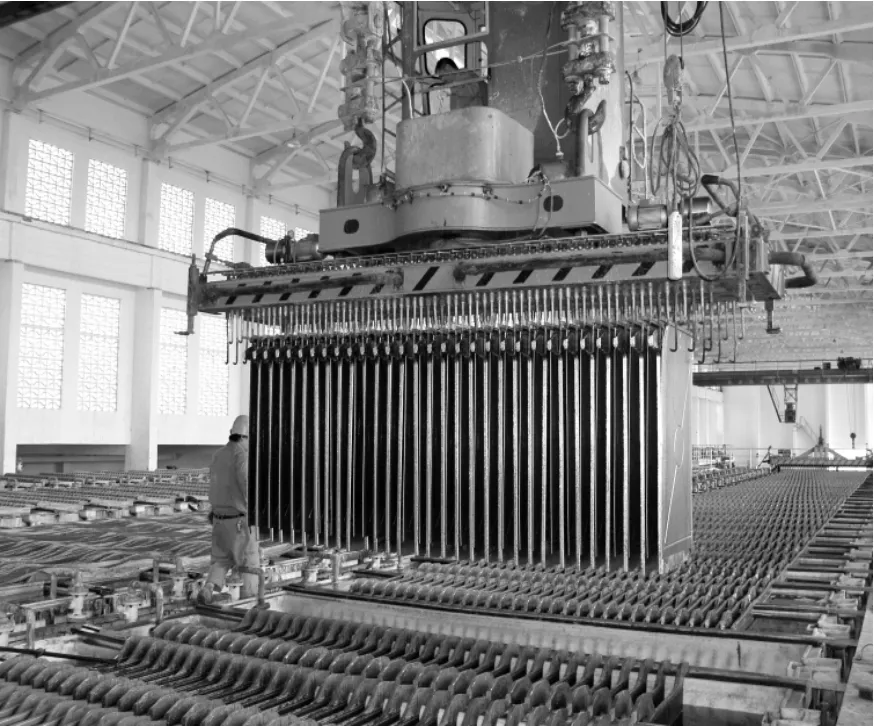
Fig.3 Electro-hydraulic operation special crane
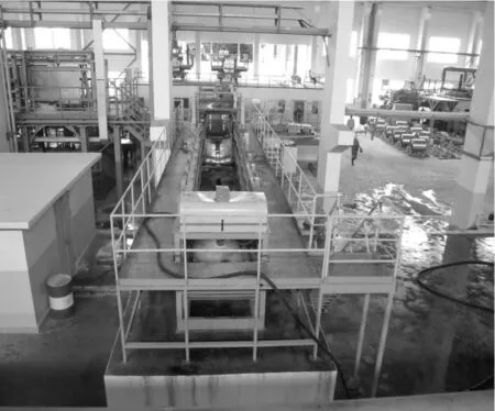
Fig.4 The lead residual anode washing equipment
猜你喜欢
杂志排行

机床与液压的其它文章
- Investigation of helical ball micro milling with variable radial immersion*
- Numerical simulation of the double suction balance type screw compressor working process*
- Parameter optimization of electro-hydraulic proportionalsystem of PID based on the improved ant colony algorithm
- Flying cutter machining and cutter design based on the machining principle of cycloid rotational indexing
- Simulation of multi-modal control in electro-hydraulicposition servo-system*
- Optimal design and security verification of flying cutterbased on finite element analysis