Design and implementation of a wireless electronic inverterwelding machine*
2014-09-05JieweiDUWeigangZHENG
Jie-wei DU,Wei-gang ZHENG
1School of Energy and Power Engineering,Wuhan University of Technology,Wuhan 430063,China;2School of Science and Technology Training Center,Wuhan University of Technology,Wuhan 430063,China
Designandimplementationofawirelesselectronicinverterweldingmachine*
Jie-wei DU1,Wei-gang ZHENG†2
1SchoolofEnergyandPowerEngineering,WuhanUniversityofTechnology,Wuhan430063,China;2SchoolofScienceandTechnologyTrainingCenter,WuhanUniversityofTechnology,Wuhan430063,China
With the development of modern mechanical automation,radio control technology has been applied in all the fields.In this paper,a kind of research method was proposed by using radio remote to control the current of inverter welding machine.It has changed the former inconvenience of cable control,which is influenced by directional infrared control and expensive tedious radio frequent control.Research results show that it is a simple,reliable technique of remote control technology,the welding current could be easily controlled,and it has good signal stabilization.
Wireless,Inverter welding machine,Remote control technology
1.Introduction
Inverter welding machine is one of the welding equipments of maintenance center that is frequently used in machinery manufacturing and construction.The welding repair technology can repair a variety of materials and a variety of types of defective parts,and this technology is not subjected to any restrictions on the size,shape,or the place.At the same time,the repaired product has high quality,and the equipment has some characteristics such as simple structure and low cost.The existing welding current regulation mode could be mainly divided into two types: wired and wireless.Although cable control has high reliability but it is not convenient to use in the real applications because its current control knob is on their body,during the real welding process,in order to ensure the welding quality,different materials correspond with different types of electrode with different diameter,and there exist different requirements for the wielding current at different welding position[1].During wielding process at a worksite far away from the welding machine,if you want to adjust the current to meet the requirements of the welding quality,the operator has to return and adjust along the welder or two operators are required to cooperate,which leads to the low work efficiency and the waste of human resources.Wireless remote control at present uses the infrared transmission and radio frequency control method,however,the infrared control has some disadvantages such as directional dependence and the influence of obstacles.Consequently,the operation is so inconvenient that radio frequency control monitoring efficiency is low,and it is prone to error with high equipment cost.In order to solve the above-mentioned problems,a new kind of research methods has been put forward,by which we can use radio remote to control inverter welding machine working current,and the experiments have been carried out to verify the feasibility.
2.Overall design of system
ZX7-250 inverter welder uses IGBT inverter technology,which has high inverter frequency,low noise and low consumption.This inverter has curved panels,an arc of function,constant current output and stable output current.The dynamic response speed could reduce the impact on current arc length fluctuation;It also has high duty cycle under the condition of temperature with 40 ℃,continuous load rate can be up to 60%[2].Therefore,on the basis of ZX7-250 inverter welder,it is modified internally to replace the original current control system with the wireless radio receiver and it could be set to A,B,C and D as four fragments.The remote control is realized through the distant radio remote control of current.The system overall design is shown in Figure 1.

Figure 1.The overall design system
The whole system adopts compact loop structure[3],the remote not only just sends out the control data,but also receives the working state data of the welding end back,and the data will be compared with preset data so as to realize the closed loop automatic correction function,which can guarantee the stability of the welding machine working current.
3.Modification scheme of system
3.1.Wirelessremotecontroldevice
Considering that current signal is stable and economical,the IC567 (PLL) is used as the wireless remote control device.In the Tx parts,IC567 makes the working current into a variable frequency oscillator.It produces four different frequencies as a FM transmitter,which is correspondent to four gear,i.e.,A,B,C and D,for the current welding inverter.In the receiver FM demodulator of the welding inverter,the signal demodulation is preceded.All of the four different IC567 have a configuration of PLL,and based on the four different frequencies the signal is produced,which is finally received by the microcontroller and will be translated into the current to adjust machine[4].The current switch to adjust control is shown in Table 1.
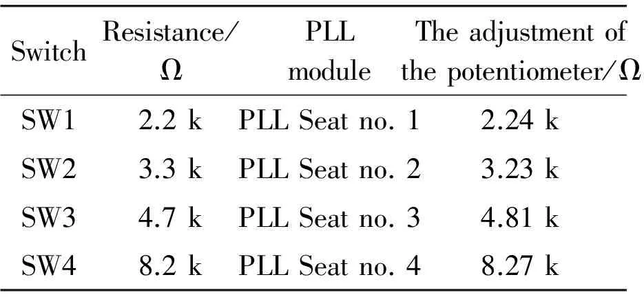
Table 1.Switch of current control table
3.2.Emissioncircuitdesign
Emission part adopts (PLL) IC567 encoder encoding,if the connection of the resistance pin is in 5 and 6,then the capacitance between 6 and 7 outputs from the 5th needles,the parallel code output as a serial,finally it is sent out through modulation circuit.The process of transmission is shown in Figure 2.Remote control is provided with a standard 9 V battery power,which is set to A,B,C and D four current gear,the switch button and the indicator lights.Remote control chip is used as an oscillator,the frequency of oscillator is calculated by equation FOSC=1.1*R*C.Therefore,by pressing the switch SW1-SW4 to choose different resistances and change the frequency.The four frequencies will be modulated and sent out in FM channel .The internal circuit diagram is shown in Figure 3.
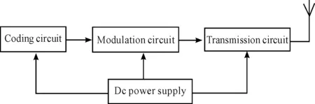
Figure 2.The flow chart of transmission circuit

Figure 3.Emission circuit diagram
3.3.Receivingcircuitdesign
As shown in Figure 4,the main components of receiving circuit of the microcontroller block are FM receiver,IC567 C51 microcontroller and 7 segment LED display lights.The output of the FM receiver is connected to all four at the input PLL (1 to 4).The internal circuit diagrams of each PLL module are also shown in Figure 4.Four PLL modules for the output port P1 of 89c51 chip,7 segment LED display drived by P0 port,port pin (P2.0 and P2.1) used to switch frequency of inverter welding machine to the current size.After signals are demodulated by the FM receiver,four PLL modules will present the signals as shown in Figure 5.Four IC567 configured to phase-locked loop device chips (pin number 8) could output a particular frequency,which is determined by the equation[5] FPLL=1.1 * R * C,to the RC components which is connected to it.Thus,they could receive the same frequency domain signal,and control the current welding inverter.
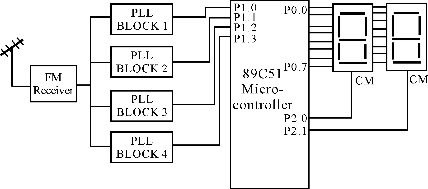
Figure 4.Micro controller block diagram

Figure 5.PLL module signal control diagram
4.The analysis of system application
Welding current control system controls electric welding machine according to the remote control command,and sends service behavior of the electric welding machine to process system.Remote end will correct and detect the errors of the original received data.If the received data is correct,the receiver will rebound a signal to the sender immediately.If the received data is not correct,the receiver will not rebound signal to the sender.The sender,if there is no received signal within a given time,will resend again.If it resend 5 times and it is still not successful,it will automatically turn to error handling,and prompt the user about the communication failure,which could improve the accuracy of the signal control.The electromagnetic wave launched by the radio remote control could be easily affected by high frequency welding current,therefore in real industrial application,we will use welding intermittent time to regulate the current.For example,if we found that excessive current welding will cause problems such as weldment,deformation,increase splash,weldment biting edge problem and burning,we could use the remote control to dispatch welding machine in standby mode,and dispatch the current button to the appropriate location and then turn the welding machine to working status.After the current is mixed up,the remote control can be closed to reduce energy consumption.So,there is no signal interference between those,welding machine can work smoothly.Object of modified remote control and circuit board are shown in Figure 6 and Figure 7.

Figure 6.Llaunch of the remote control

Figure 7.Welder signal receiving device
5.Conclusion
Through the above theoretical analysis and experimental verification,the method of using radio remote control to control the inverter welding machine working current is feasible.By using this method,the welding quality could be improved,cost of the device is relatively low,and the operation is simple and it is easy to realize reconstruction of old welder as well.Meanwhile,at the present,with the shortage of manpower and material resources,the welding automation technology will become the mainstream of the times.
[1]Zhang guangxian,Lipeng.Invert Welder and Digital Control Technology[J].Electric welding machine,2012(6):17-22.
[2]Zhou ruitao,Cui wenlu,Chen kaijun.Design and Application of Remote Wired Control Based on ZX7-250 Welding Machine[J].Heat Technology,2013,(9):220-221.
[3]Zhou Qing.Study of Wireless Control Welding Machine Based on Spread-spectrum Communication Technology[D].Taiyuan,2006.
[4]Liang wenguang,Shao chengji.Welding Current Remote Control Technology[M].Beijing: Science Press,1987.
[5]Pateiek A,Newbury J,Gargan S.Two-Way Communications Systems in the Electricity Supply Industry[J].IEEE Transaction on Power Delivery,1998,13(1):53-59.
摘要:利用Excite_TD软件构建了本田125 mL单缸四冲程汽油机配气机构运动学与动力学模型,通过分析多项动力加速度函数(POL)与分段加速度函数(ISAC)凸轮型线设计方法的性能指标,选择ISAC优化设计可变循环往复活塞式发动机(VCRPE)二冲程与四冲程工作模式的进、排气凸轮型线。为了验证凸轮型线设计的合理性,利用SolidWorks构建并分析了相应配气机构的多体动力学模型,对比Excite_TD和SolidWorks模型的动力学分析结果表明,两者分析数据吻合较好,验证了凸轮型线优化设计的准确性。
关键词:往复活塞式发动机;可变循环;配气机构;凸轮型线;优化设计
中图分类号:TK423.41
无线电遥控型逆变焊机的设计与实现*
杜杰伟1,郑卫刚†2
1武汉理工大学 能源与动力工程学院,武汉 430063;2武汉理工大学 工程训练中心,武汉 430063
随着现代机械自动化程度的提高,无线电控制技术已经渗透到各个领域。为此,提出了一种使用无线电遥控器控制逆变焊机工作电流的研究方法。它解决了原来有线控制的不便、受方向性限制的红外线控制以及价格昂贵繁琐的射频控制等问题。研究结果表明:该焊机电流易于控制,信号稳定,是一种简单、可靠、可推广的远程控制技术。
无线电;逆变焊机;远程控制
U644.45+5
可变循环往复活塞式发动机凸轮型线优化设计*
邸立明†1,孙万利2,师 颖3,王文峰1
1燕山大学车辆与能源学院,河北 秦皇岛 066004;2沈阳佳实司法鉴定所,沈阳 110023;3交通运输部公路科学研究院,北京 100088)
2013-09-12
*Project supported by Self-dependent Innovation Fund Program of Wuhan University of Technology(136805007)
† Wei-gang ZHENG,E-mail:zfeidiao@126.com
10.3969/j.issn.1001-3881.2014.06.009
猜你喜欢
杂志排行

机床与液压的其它文章
- Investigation of helical ball micro milling with variable radial immersion*
- Numerical simulation of the double suction balance type screw compressor working process*
- Parameter optimization of electro-hydraulic proportionalsystem of PID based on the improved ant colony algorithm
- Flying cutter machining and cutter design based on the machining principle of cycloid rotational indexing
- Simulation of multi-modal control in electro-hydraulicposition servo-system*
- Optimal design and security verification of flying cutterbased on finite element analysis