Recent Developments in Radar Waveforms
2014-08-05CaoSiyangZhengYuanfang
Cao Si-yang Zheng Yuan-fang
(Department of Electrical and Computer Engineering, The Ohio State University, Columbus, Ohio 43210, USA)
Recent Developments in Radar Waveforms
Cao Si-yang Zheng Yuan-fang*
(Department of Electrical and Computer Engineering, The Ohio State University, Columbus, Ohio 43210, USA)
With the development of high speed digital processor and solid state power electronics, more flexible waveforms become feasible to achieve by modern radar systems. In fact, the choice of waveforms has a significant impact on the performance of radar systems. In this paper, we review the conventional radar waveform design as well as explore the new generation of waveforms via different theoretical methods, including the most recent wavelet based waveforms. It is shown that the waveform design supports the radar advancement for more intelligent and divergent applications. In this endeavor, radar waveform design plays an even more important role in reaching specific purposes, in addition to range and speed detections, and further improves the performance and application scopes of radar systems.
Radar waveforms; Pulse compression waveform; Phased waveform; MIMO radar; Wavelets
CLC index: TN958
1 Introduction
The radar waveform design is for improving radar performance, including maximum Signalto-Noise-Ratio (SNR), and optimal extraction of target information, such as range, speed, shape, and recognition[1,2]. Take Synthetic Aperture Radar (SAR) as an example. Fig. 1 shows the strip-map SAR simulation results, comparing the traditional Linear Frequency Modulated (LFM) waveform with a Wavelet-Based radar Waveform (WBW). The Peak Signal-to-Noise Ratios (PSNR) of the LFM and the WBW waveforms are 19.77 dB and 21.77 dB, respectively. These results indicate that different waveforms can produce significantly different detection results for radar systems. Because of the potential improvement on radar performance, radar waveform has been a key topic of research for a long time and is still active today.
In this paper, we review the progress in the radar waveform designs in recent years. In fact, the waveform design has a long history research and is still under active investigation for existing radar systems. With the advent of Ultra-Wide Bandwidth (UWB) electronics, advanced digital signal processing, high speed computing, high frequency electronics, and solid state power amplifier, emerging radar systems (such as UWBradar, Multiple-Input and Multiple-Output (MIMO) radar, cognitive radar, etc. are expecting more from their waveforms. These new technologies enable the scientists and engineers to implement new waveforms, which were not possible when these new technologies were not available, to achieve significantly better performance for conventional radar systems, namely target detection including its range, speed, and shape.
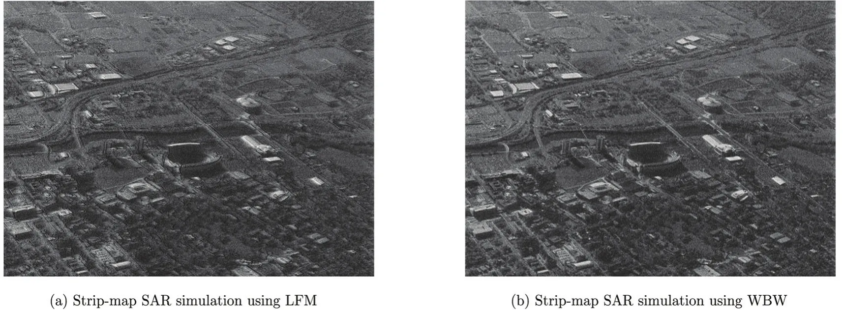
Fig. 1 Strip-map SAR simulation using LFM and WBW
The study on the waveform design is also pushed by more applications of radar in our daily life. Traditional radar has been primarily used in military for target detection or for image construction. Today radar sensing is being used in a wide scope of applications including, for example, automotive radar. It is perceived that automotive radar will be ubiquitous in the future, installed on every vehicle for safety consideration, even for fully automated vehicles. In addition, microwave radars are also being used for human detection on mobile robots, and for probing of concealed objects, etc.. Different applications naturally demand for different waveforms in order to push the performance to the limit, for any particular purpose of applications. Researchers are therefore continuously studying the radar waveform design, from the fundamental pulse compression to more advanced waveforms for future radar systems. In the rest of this paper, we review the recent developments of radar waveform design, which are by no means inclusive due to the limit in time to generate this report and a massive amount of papers published in the literature.
The structure of the paper is arranged as follows. In Section 2, fundamental pulse compression waveform as used by most of today’s radar systems is discussed. It is particularly mentioned that the sidelobe in pulse compression is a significant issue related to the resolution of range detection. In Section 3, phase coded waveforms are introduced for the purpose of reduction of sidelobes. In Section 4, the newly developed MIMO radar system and its related waveforms are presented. The fundamental theories and approaches for resolving target parameters by MIMO are discussed. In Section 5, the theory and design of WBW are introduced. The latter waveform represents one of the most recent developments in radar waveform designs. Consequently, the theory and the design principle of WBW is introduced in more details than other waveforms. In Section 6, various waveform designs for different purposes of applications are discussed. Finally, the paper is concluded in Section 7.
2 Radar Waveform Fundamentals
Similar to wireless communication systems, radar typically transmits a baseband signal carried by a high frequency sinusoid signal, i.e.:

where s(t)is the baseband waveform and fcthe carrier frequency. Because of the properties of radiated electromagnetic energy, the ideal received signal reflected by a single point target will be:

In the above equation, the time delay τ is caused by the range of the target, the Doppler frequency fdis determined by the radical velocity of the target, and the amplitude A is affected by the cross-section of the target when the target range, transmitter and receiver gains are given. Apparently, how the three parameters A, τ, and fdare alternated can reveal the information associated with a target.
The range resolution is the ability of a radar system to resolve targets along the range direction. Take the rectangular signal () rectt/ T as the baseband waveform for example, where Tis the duration of the radar pulse (radar pulse width), and the rectangular function is defined as below:

The received signal reflected from a single static target is:

where R is the range of the static target and the speed of light. The term 2R/c is equivalent to the delay τ in Eq. (2). This is because the electromagnetic energy typically travels through the space in a straight line at the constant speed c. Thus delay τ can be used to measure the range of the static target. When the rectangular waveform is used to detect two static targets, the received signal is:
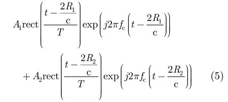
where R1and R2correspond to the positions of the two targets, respectively. If the two targets are very close to each other, the two reflected signals generated by the two different targets mix together (Fig. 2), and are difficult to resolve due to the Radar Pulse Width (RPW).
The range resolution using the rectangular waveform can be defined using the bandwidth of the waveform B as:

According to Eq. (6), radar can improve its range resolution via different waveforms so long as the bandwidth is increased. The challenge is how to increase the range resolution, while transmitting enough energy for long range target detection. According to Eq. (6), one can increase the range resolution via a high bandwidth waveform, while the pulse width can be maintained large. Therefore, a high timebandwidth product waveform has the potential to increase the range resolution without sacrificing the transmission power. Scientists call this kind of waveform pulse compression waveform.
One of the most widely used pulse compression waveforms is LFM waveform[3]or the chirp waveform. The frequency of LFM linearly increases (up-chirp) or decreases (downchirp) with time. Therefore, the waveform is feasible to be achieved by the analog circuits. The mathematical equation for LFM is:

where k is the rate of frequency increase or the chirp rate. The instantaneous frequency of the baseband waveform is a function of time: f(t)= ktrect(t / T).In the beginning of the pulse, f(-T /2)=-(kT)/2.At the end of the pulse, f(T/2)=(kT)/2.As a result, the bandwidth of LFM is kT. The time-bandwidth product of LFM is kT2. According to Eq. (6), the LFM waveform can simply increase its chirp rate k in order to obtain the high range resolution and keep a wide pulse width at the same time.
The ambiguity function is used to evaluate how the returned pulse is distorted due to the receiver matched filter:

When the Doppler frequency is not considered, the ambiguity function reduces to the autocorrelation ofs(t), i.e.

Fig. 3 shows an LFM waveform with a 3 μs pulse width and 64 MHz bandwidth. The autocorrelation of the waveform produces a sharp mainlobe with serious sidelobes. The Peak to SideLobe Ratio (PSLR) of LFM is 13.2 dB. -These sidelobes are highly responsible for blocking nearby weak reflections from small targets or for blurring SAR images.
One traditional way to suppress the sidelobes is using windowing procedures. Harris[4]provides an extensive list of windows and their properties. Coming along with the sidelobe suppression, the windowing procedure brings a side effect of increased mainlobe width, which also degrades the range resolution in target detection. Compared with LFM, the stepped frequency waveform[5]increases (or decreases) its frequency discretely by a fixed frequency increment (or decrement) each time. The Frequency Jump Burst (FJB)[6]divides LFM into multiple sub-pulses in the time domain, and transmits each separately. Consequently, these discrete versions of LFM perform similarly as the original LFM waveform in range detection.
Aiming at suppressing range sidelobes, some researchers have selected nonlinear frequency modulated waveforms. Griffiths[7]generates nonlinear frequency waveform using equation:


Fig. 3 Baseband LFM waveform and its autocorrelation
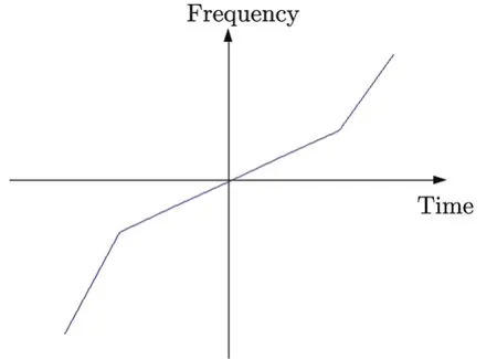
Fig. 4 Piecewise nonlinear FM waveform
A central linear FM component(t) and the additional higher FM rate portion(t) are plotted in Fig. 4. The PSLR of his proposed waveform is- 50.4 dB, which is much lower than the traditional LFM waveform. Instead of the piecewise nonlinear FM waveform, Witte[8]further studies a continuous nonlinear FM waveform to suppress the sidelobes to below -70 dB. However, the nonlinear FM waveforms increase the width of the mainlobe compared with LFM, and thus to lower the range resolution. In addition, the nonlinear FM waveforms are sensitive to the Doppler effect. That is, the range of the target is sensitive to the speed of the target. Different speeds can result in different range data for an identical target. Consequently, the range resolution becomes lower when the target is in motion. The details of this issue will be further discussed in Subsection 5.4 of this paper.
3 Phased Waveform
Another approach for designing new radar waveform is through phased coding. The phased coding approach introduces a set of pulse compression waveforms. This approach divides the radar pulse into sub-pulses, and then phased coding is performed on each sub-pulse. A wellknown phased coding approach is Barker coding[9], which codes each sub-pulse with a phase shift of 0° or 180° accordingly as shown in Fig. 5.
By employing the phase coding, the sidelobes of the autocorrelation of the Barker code have an equal magnitude of1/N as shown in Fig. 6, where N=7 is the length of the code. However, Barker codes cannot be of arbitrary length. The maximum possible length is N=13, resulting in limited sidelobe suppression. A set of concatenated Barker codes can increase the length of the waveform, but the sidelobe suppression is still limited by N=13. Therefore, the minimum PSLR of the Barker code is -22.28 dB .

Fig. 5 Barker coded pulse with seven sub-pulses
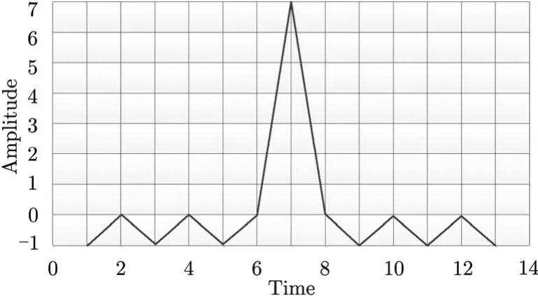
Fig. 6 Autocorrelation of a Barker coded pulse
Another phase coding approach is the Golay complementary sequence, which can be used to construct bi-phased waveforms as well. The difference is that the Golay code consists of a pair of bi-phased sequences. The summation of the autocorrelations of the two sequences produces a delta function. As a result, transmitting the pair of bi-phased sequences of waveforms separately in time can totally remove the sidelobes in range. However, the bi-phased code is highly sensitive to the Doppler shift. To overcome this problem, Pezeshki et al. propose using the Prouhet-Thue-Morse (PTM) sequence to construct Doppler-resilient sequences of Golay pairs[10,11]. However, the PTM sequence requires transmitting a long sequence of pulses. Galati[12]proposes to nest an up-chirp and downchirp waveform into complementary codes, which produces range sidelobes similar to that of LFM.
In addition to bi-phase coding, polyphase codes provide more flexibility than bi-phase codes. The Frank code[13]or its modified versions i.e. P1, P2, and Px codes[14], are polyphase codes that approximate the LFM waveform. Some other LFM-like polyphase codes are P3 and P4 codes[15]as well as Golomb polyphase codes[16].
There are intensive studies on finding Constant-Amplitude Zero-AutoCorrelation (CAZAC) waveforms. Early works use different names for this kind of waveform[17]including: polyphase codes with good periodic[18]or optimum correlation properties[19], perfect autocorrelation[20]or root-of-unity sequences[21], bi-unimodular sequences[22], and bent functions[23]. To identify an appropriate CAZAC waveform for the radar is still an interest in the radar community[24]. Benedetto and Donatelli[17]propose the periodic CAZAC code, which can produce the mainlobe without sidelobes. In Ref. [20], a polyphase code with the length of 75 is shown as an example. When unimodular is not a limitation, Soltanalian[25]found virtually perfect phasequantized sequences with extremely small sidelobes (PSLR is less than-250 dB). Unfortunately, the magnitude of the sequence is not constant, and the dynamic range of the transmitted waveform is not as good as other polyphased waveforms. Chen[26]utilizes a cyclic algorithm to synthesize probing sequences with good aperiodic autocorrelation properties, and to suppress the range sidelobes to a lower than-30 dBPSLR via a sequence of length 400. Stringer[27]applies Multi-Objective Evolutionary Algorithms (MOEAs) to the phase coded waveform design, and has achieved a lower than-30 dBPSLR via a sequence of length 64. Jakabosky[28]applies the Marginal Fisher’s information algorithm to suppress the sidelobes of a continuous phased waveform to -30 dB via a sequence of length 64.
When SNR is not a critical issue for the receiver, bi-phase or polyphase codes using mismatched filter is a selection. Baden[29]shows an orthogonal filtering approach for the orthogonal code pairs, and generates filters for mismatched pulse compression with low sidelobes near the mainlobe. The distribution of the sidelobes’ energy can be adjusted by a weight function. Griep[30]introduces mismatched polyphase codes with low PSLR for a pulse compression system, which has specific temporal and frequency characteristics. Polyphase codes’limitation is the sensitivity to the Doppler effect[31], and the complexity of waveform generation for various purposes of applications.
To decrease the complexity of radar systems, some of today’s radar designs use Pseudo-Random-Noise (PRN) code approaches[32,33]. The PRN codes are easy to generate, and can achieve relatively good sidelobe suppression[34]. In recent studies, Axelsson[35]studies random bi-phase modulated waveform for improving the range resolution, but the waveform introduces high sidelobes. Pralon[36]studies random phase/frequency modulated waveform for effective sidelobe suppression. Another recent study on PRN shows that complex PNR waveforms are capable of reducing the nearsidelobes significantly[37,38].
In recent years, UWB radar is studied for the high range resolution due to the use of wide bandwidth. Compared with traditional sinusoid carrier based waveforms, UWB radar transmits very short pulses with extremely wide bandwidth. In Ref. [39], Gaussian monocycle shapes are used for UWB. The pulse compression of the UWB radar usually uses a train of properly weighted and shifted Gaussian pulses based on selected codes[40]. Therefore, the waveform design is equivalent to finding a good range ambiguity bi-phase code. Nijsure[41]studies a bi-phase code based on Walsh-Hadamard code matrix for the UWB cognitive radar networks.
A different approach related to coding waveform is the frequency coding waveform. Similar to the phase coded waveform, the Costas waveform divides a relatively long pulse into N equal-duration sub-pulses with each sub-pulse centered at a different frequency. Generally, the frequencies are spaced equally. When the frequencies increase linearly with the sub-pulses, a stepped frequency waveform will generate. As discussed in Section 1, the stepped frequency waveform performs similarly as LFM, whose ambiguity function (Eq. (8)) produces sidelobes in both the range and Doppler frequency directions. The Costas waveform[42]transmits a sequence of hopping-frequency waveforms.
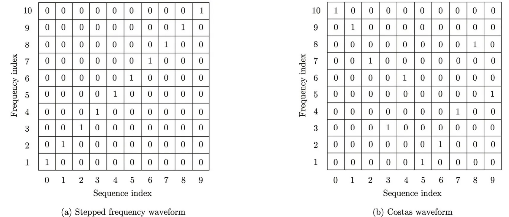
Fig. 7 Stepped frequency waveform and Costas waveform
Fig. 7 shows the comparison between the stepped frequency waveform and the Costas waveform with 10 sub-pulses. The row represents the time sequences, and the column denotes the frequency. A ‘1’ specifies the frequency associated with the indicated sub-pulse. If the ambiguity function of Costas waveform is discretely calculated according to the sub-pulse duration and unit hopping-frequency, the ambiguity function will have an ideal range and the Doppler sidelobe behavior, which provides unambiguous Doppler and range information. However, the continuous ambiguity function still shows -13.2 dB sidelobes in the range and Doppler frequency directions. In a recent study, Bell[43]attempts to further push away the annoying sidelobes using a hopping-frequency waveform. However, the near-sidelobes still exist due to the property of the autocorrelation of the hopping frequency waveform. We will discuss a wavelet-based waveform instead of hoppingfrequency waveform in Section 5.
4 MIMO Radar Waveform
Because of the development in the areas of Field-Programmable Gate Array (FPGA) and Digital Signal Processor (DSP) in recent years, pulse compression in the digital domain becomes possible. Fig. 8 shows a digital system for inphase and quadrature signals in a single receiver. After demodulation and filtering, the received analog signals are converted into digital signals. The complex baseband signals are then crosscorrelate with the reference waveform in the frequency domain via Fourier transform to increase the digital processing speed. The results then go through an inverse Fourier transform channel to obtain the cross-correlation in the digital domain.
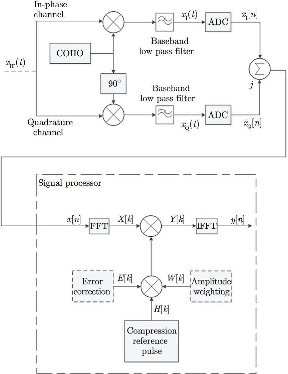
Fig. 8 Digital pulse compression
Taking the advantage of digitalization in radar applications, MIMO radar systems have been studied intensively in recent years. Different from the phased array radar, which transmits an identical waveform in all the antenna elements to generate a high gain in a specific direction, the MIMO radar transmits different waveforms on all the antenna elements involved. In Ref. [44], Li introduces the MIMO radar waveform in details.


The estimation of the targets parameter can be expressed as below:
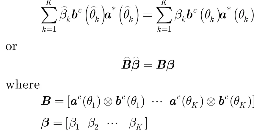
When the transmit array is the same as the receive array, the sample covariance matrix of the target reflected waveforms can be expressed as

where

From the above analysis, one can see that constructing such a set of orthogonal waveforms is a preliminary step for the MIMO radar. Various approaches have been developed to design new radar waveforms such that the advantages of the MIMO radar can be fully taken. Kemkemian[45]obtains the orthogonality between the transmitted waveforms via Doppler Division Multiple Access (DDMA). Rabideau[46]discusses the Code Division Multiple Access (CDMA), Time Division Multiple Access (TDMA), and Frequency Division Multiple Access (FDMA) techniques, and further uses these conventional techniques to create sets of displaced waveforms for the MIMO radar. Cai[47]has designed orthogonal binary code waveforms for the MIMO radar. Takayama[48]further verifies the gold code based MIMO radar in the radar platform. Galati[49]proposes to use Costas codes and the phase noise signals to generate orthogonal waveforms for the MIMO radar. Han[50]and Chen[51]use frequency hopping codes. Majumder[52]presents a set of waveforms generated by Direct Sequence Spread Spectrum (DSSS) coding on LFM. Hua[53]utilizes Costas Array Coding (CAC) and Quadratic Congruence Coding (QCC) in the MIMO radar. Sharma[54]uses phased coded waveforms based on the Kumar sequences. Yang[55,56]produces chaotic phased coded waveforms for the MIMO radar.
One advantage of the MIMO radar is its ability to resolve more targets in different directions compared with the traditional phased array approach. Consider the situation that the transmitter array and the receive array are different in number, i.e. Mt≠Mr. If the receive array is the subset of the transmit array, ac(θ)⊗bc(θ) has only Mt+Mr-1 distinct elements. However, when there are no sharing elements between the transmit and receive arrays, ac(θ) ⊗ bc(θ)hasdistinct elements. Therefore, the number of maximum possible distinct objects to be resolved by the MIMO[44]is Kmax∈max((Mt+Mr-2)/2,(MtMr)/2), which is up to Mttimes that of its phased array counterpart.
Another advantage of the MIMO radar is its capability to adjust its beamforming via the waveform design. Because the power in a direction θ is given by:

Rxxcan be optimized to control the spatial power distribution via the transmitted waveform. Li[44]considers different spatial beam patterns, such as the uniform elemental power for target searching, and multiple beams with minimized sidelobes for multiple targets tracking.
For applications in reality, the target response should be considered as a Finite Impulse Response (FIR), which can be a Gaussian random vector with zero mean. Based on the information theory, Tang[57]proposes the MIMO radar waveform design in colored noise to maximize mutual information and relative entropy. Yang[58]designs waveforms that maximize the conditional mutual information between the random target impulse response and the reflected waveforms, and develop transmitted waveforms that minimize the Mean-Square Error (MSE) in estimating the target impulse response. Naghibi[59]designs the MIMO radar in the presence of clutters.
Waveform design for MIMO is for improving the performance of the new radar system to meet the orthogonal waveform requirement as transmitted by individual radar elements in MIMO. Research to discover new radar waveforms for improving the performance in both conventional and new structures still continues. In the next section, we introduce an emerge effort in recent years, which is called waveletbased waveform.
5 Wavelet-based Waveform
5.1 Introduction of wavelet
Wavelets and wavelet transforms have been successfully utilized in audio, image and video processing in recent years, including the JPEG2000 image compression standards[60]. However, there are only limited studies using wavelets to construct radar waveforms. Mohseni[61]generates UWB radar waveforms via wavelet packet based on Orthogonal Frequency Division Multiplexing (OFDM) radar signals. Lester[62]studies periodic continuous wavelets as radar waveforms. Yin[63]discusses the relationship between wide-band ambiguity functions and wavelet transforms. Wang[64]proposes transmitting single wavelet functions and performing wavelet decomposition at the receiver instead of using matched filters. Bonneau[65]uses wavelet packets as filter banks to decompose the chirp waveform according to the target spectral energy. The purpose is to improve radar detection success. While the SAR platform employs the chirp waveform to generate the sinc function in the range and azimuth directions, Xu[66]uses wavelet transform to improve moving target detections. However, none of these works consider using the discrete scaling function and wavelets to construct radar waveforms except an early work by the current authors[67].
In our pervious paper, a WBW[68]is proposed for effective sidelobe suppression on target detection. To generate WBW, the discrete orthogonal wavelets are used for the waveform design. To compare with the conventional LFM occupying the same bandwidth, the timefrequency diagram of LFM and that of WBW are shown in Fig. 9. Both waveforms have the same bandwidth of δF=64δf , whereΔfis the bandwidth of a sub-pulse in WBW. The LFM waveform linearly and continuously increases the frequency of the waveform, but WBW increases the frequency discretely by a subband according to the packets used in the waveform. One can see time-frequency blocks in WBW replacing the single line of LFM. That is because in each time duration Δt, there is a wavelet packet which spans a subband of the spectrum. WithinΔt, one can not resolve a particular frequency for every point of time, but only a subband spanned by the corresponding wavelet. WBW is more flexible to adjust the amplitude and phase for specific frequency subbands since the adjustments can be focused on a particular wavelet packet.
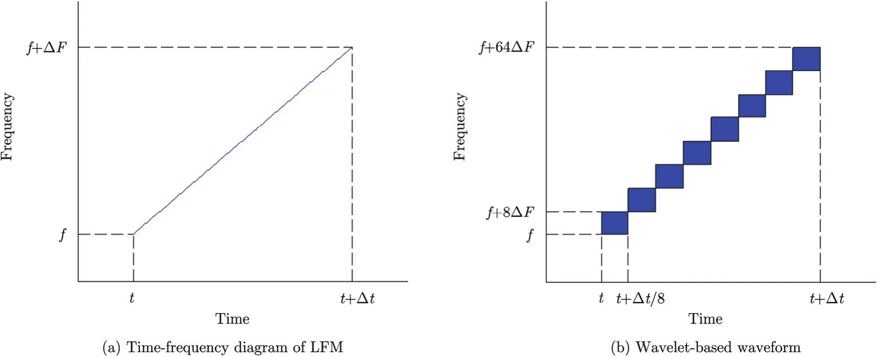
Fig. 9 Time-frequency diagram of LFM and wavelet-based waveform
As discussed before, the sinusoid based waveforms (such as LFM, stepped frequency waveform, Costas waveform) generate sinc function based range detection results. The near sidelobes can be suppressed by applying the window function, or introducing the non-linear frequency component. However, these methods increase the mainlobe width and reduce the resolution. For WBW, it generates small sidelobes naturally, and no further suppression technique is needed. Take eight Daubechies order-4 wavelet packets as an example (Fig. 10), the summation of the autocorrelations of 2Nwavelet packets is the 2N-timescompressed autocorrelation of the scaling function (Fig. 11). The autocorrelation of the D-4 scaling function generates a sharp mainlobe with very small sidelobes, and its PSLR is -22.69 dB.Theoretical proof of this new radar waveform can be found below in the following subsection.
5.2 Wavelet fundamental
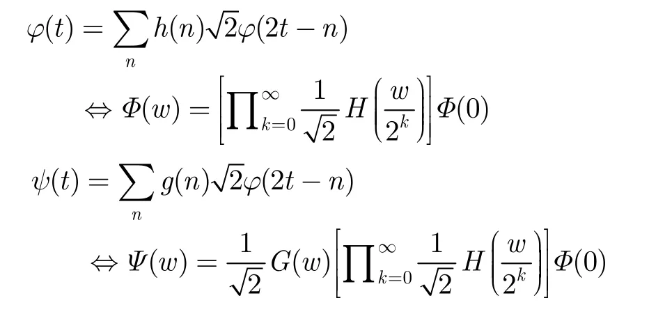
The basic recursion equation for generating the scaling functionϕ(t) and the wavelet functionψ(t)are shown below[68]:
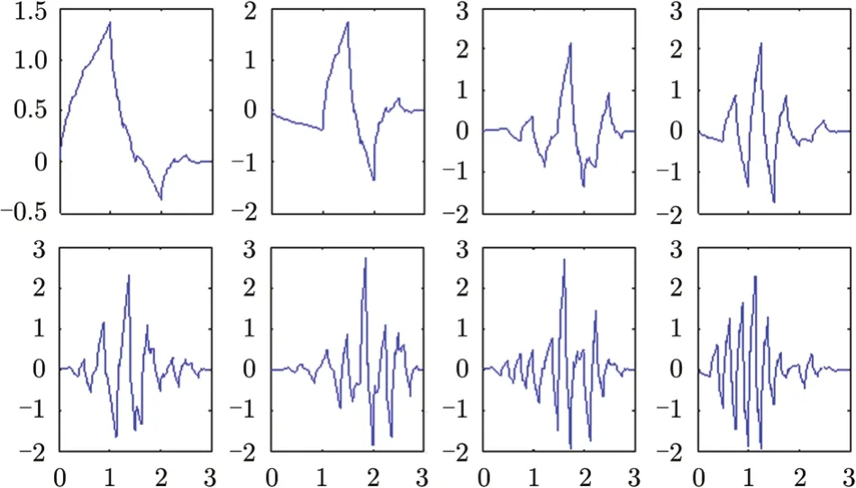
Fig. 10 Waveforms of individual D-4 wavelet packets
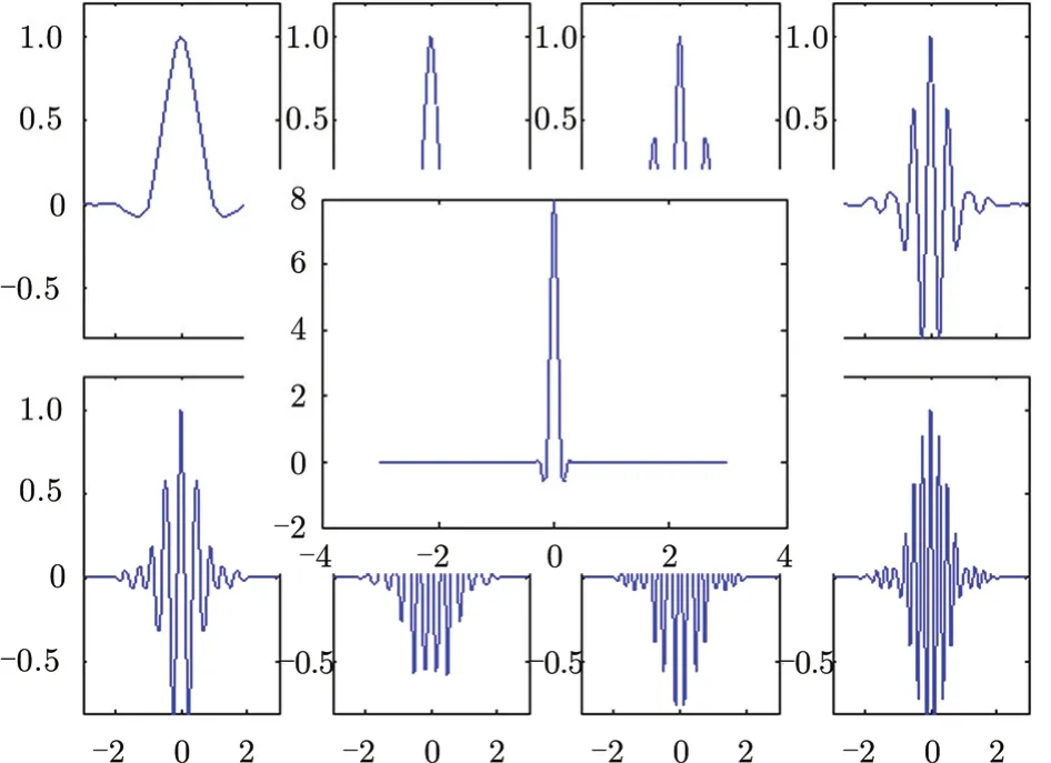
Fig. 11 Autocorrelation of eight D-4 wavelet packets (behind the front layer) and summation of eight autocorrelations (the front layer)
where

and L is the length of the coefficientsh(n). According to the wavelet theorem, different coefficientsh(n)generate different wavelet waveforms. However, the coefficients are not arbitrarily selected, but with necessary conditions which are listed as below:
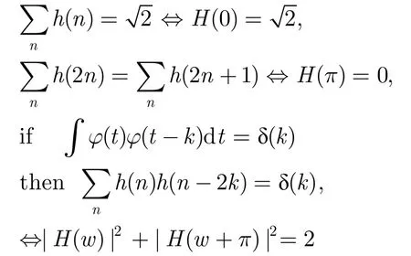
whereH(w) is the frequency domain of the coefficients h(n). According to the relationship between g(n) and h(n), we have G(w)=H(w+π), where G(w) is the frequency domain of the coefficients g(n). H(w) is the low frequency part, and G(w) is the high frequency part of the spectrum spanned by the scaling function and the wavelet, respectively.
Wavelet packets can further divide the scaling function and wavelet into narrower bandwidth signals, called wavelet packets. Take four wavelet packets as an example. They are obtained by decomposing the scaling function and the wavelet each into two narrowed-by-2 bandwidth functions:
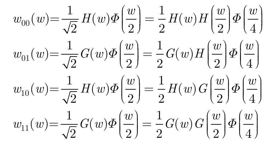
According to the necessary condition of the wavelet coefficients, the summation of the autocorrelation of 2Nwavelet packets is the autocorrelation of narrow-by-2Nscaling function. This fact can be drawn from the equations as below:
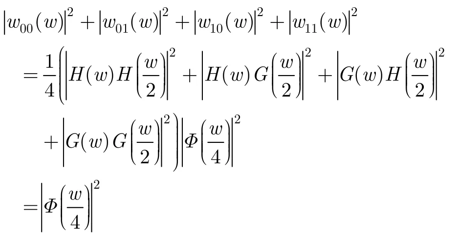
This equation is further confirmed in Fig. 11, which shows the summation of eight autocorrelations of individual wavelet packets.
5.3 Wavelet based waveform
The wavelet based waveform is constructed by concatenating the wavelet packets in a chosen sequence of wavelet packets. Suppose the sequence of ordered wavelets is:

where for any j, wj(t) represents a wavelet packet when0 ≤t ≤Δt;otherwise, wj(t)=0. Note that w0(t) is the scaling function. Then the WBW is given by:
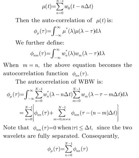
As we discussed in Subsection 5.2, the summation of the autocorrelations of the wavelet packets equals the autocorrelation of the narrowed scaling function. Regardless of the sequence of the wavelet packets, the autocorrelation of the wavelet sequence has a resolution of Δt/ N. However, whenτ≥Δ tthe autocorrelation of the waveform is completely determined by φnn(τ),which is the crosscorrelation of the wavelet packets.
WBW generates far-sidelobes because of φnn(τ). To suppress far-sidelobes, one strategy is to adjust the sequence of the wavelet packets similar to the way of the Costas waveform. WBW hops its frequency bands so that the farsidelobes can be distributed as one desires[69]. Another strategy is to sense the detected area using different wavelet packets each time[70], and then use pulse integration to generate the compressed waveform without far-sidelobes. Fig. 12 shows the comparison between WBW and LFM, with the same non-zero duration and bandwidth, in the time domain. Because WBW pushes the far-sidelobes far away from the mainlobe, the sidelobes of WBW are very small compared with LFM as shown in Fig. 13, while the mainlobe generated by WBW is still narrow.
While the advantages of WBW is obvious, one challenge is that the power amplifier needs a larger dynamic range than that for LFM, as LFM has a constant amplitude while WBW has variable amplitude in its waveform. The advent of new solid state technologies in recent years alleviates this problem significantly.
5.4 Moving target detection using different waveforms
The Doppler effect shrinks or spreads radar waveforms when a source is moving toward or away from the receiver. This change of waveform shape is due to the relative motion between the source and the receiver. To understand the Doppler effect, first assume that the length of a transmitted waveform is T. If both the source and the receiver of the sensing system are stationary, the receiver will receive the waveform with the same duration T. Now if either the source or the receiver moves toward the other, the receiver will receive the complete waveform in a time shorter than T. This is because the receiver is receiving the waveform in a speed that the source is producing plus a relative speed between the receiver and the source. In the other direction, if the source and the receiver are moving apart, the receiver will receive the complete waveform in a time longer than T.

Fig. 12 LFM waveform and D-4 wavelet packet waveform with same bandwidth and non-zero duration

Fig. 13 Autocorrelation of LFM waveform and autocorrelation of D-4 wavelet packets waveform with same bandwidth and pulse duration
In the radar systems, however, the speed of the waveform transmission is the speed of light, which is much faster than the relative speed between the sensing system and the target. Shrink or spread of the waveform is very slight, and thus difficult to measure. On the other hand, the carrier frequency is sensitive to the speed of the target. Therefore, speed detection uses the variation of carrier frequency to measure the speed between the sensing system and the target. Assume that the transmitted carrier frequency isfc, and the received carrier frequencyfris:
where v is the relative speed between the sensing system and the target, and c is the speed of light. The Doppler frequency (or “beat frequency”) is:

However, for a wide bandwidth waveform the Doppler frequency is applied to not only the carrier frequency, but also the other frequency of the transmitted waveform via spread (or shrink) of the transmitted waveform. This spread (or shrink) causes errors when using the Doppler frequency to measure the speed of an interested target.
To estimate the target velocity accurately, the Doppler radar sacrifices its range detection ability to achieve high speed resolution. It transmits a beam of electromagnetic radiation waves, tuned to a precise frequency, towards an interested moving target. The target speed is resolved accurately according to Eq. (12). To obtain range information, pulsed Doppler radar uses the rectangle pulse for the range detection. Unfortunately, the rectangle pulse, utilized by the pulse Doppler radar, can not produce enough power for the long range detection.
The Frequency-Modulated, Continuous-Wave (FMCW) waveform can be used by the shortrange measuring radar to determine both speed and range of a single target. Similar to the Doppler radar, the FMCW radar transmits continuous wave, but the FMCW waveform utilizes triangular modulation[71], i.e., its frequency periodically increases and decreases alternatively in a same slope as time increases. The FMCW receiver cross-correlates the received signal with the transmitted waveform, and generates two single frequency signals, which can be used to determine the distance and velocity of the detected target. The limitation of FMCW is the number of detected targets. The advantage of the continuous wave radar is its low cost to be realized due to the much smaller sample rate than the Nyquist sampling rate of the transmitted waveform.
Frequency-Shift Keying (FSK) is another continuous radar waveform used in the automotive radar for estimating range and velocity of the moving target with a low cost. The FSK radar alternatively transmits two single frequency signals. Because the frequency gap between the two signals are very small, the two received single frequency signals generate almost the same Doppler frequency. However, the phases of the two received signals are different. This difference is directly determined by the range of the target. After obtaining the Doppler frequency and the phase difference, the FSK radar can measure both the range and the velocity of the moving target. However, because the maximum phase difference is 2π, there is an ambiguous maximum range limitation of FSK. Rohling[72]proposes an LMFSK waveform combined FSK and LFM to overcome the ambiguous range.
Note that all the continuous waveform radar does not process the received signal via matched filter, or analyzed by an ambiguity function. The radar can take the advantage of its extreme lower sampling rate compared with the Nyquist rate of the transmitted waveform to build the low rate analog-to-digital and digitalto-analog converters. Consequently, the cost of building the continuous radar can be signifycantly reduced. However, without the matched filter for increasing SNR, the continuous wave radar is not ideal for long range detection.
LFM is still widely used as the long range detection waveform for estimating ranges and velocities of multiple targets simultaneously. However, LFM generates the Doppler spread term[73]because of its frequency modulation mode. This term is highly responsible for both range and speed ambiguities. According to Eq. (7), the deramped-signal frequency for a moving target is (2v fc)/c+(( 4v k)/c)t,where (2vfc)/c is the Doppler frequency used to detect the object velocity, (( 4vk)/c)t is the spread term of the Doppler frequency. The latter, caused by frequency-modulation, degrades the speed detection accuracy, and further decreases the SAR radar azimuth resolution. There are a few studies tackling this issue. Tao[74]analyzes the Doppler spread term, and reduces the spread by introducing a scaling processing. However, the mitigation relies on the estimation of the target speed and further post processing. Similarly, Liu[75]needs the coarse estimation of the target radial velocity and post processing to reduce the Doppler effects.
A prospective solution is to use the amplitude modulated waveform to overcome the limitation of frequency modulated. Taking WBW as an example, suppose the transmitted signal to be the baseband signal w(t)carried by a carry frequency fcsuch that the modulated WBW waveform iss(t)=w(t) exp(j 2πfct).The carrier frequency of the received signal is fc-(2vfc)/c. After removing the carrier frequency, one can obtain the Doppler frequency without any interference term(2vfc)/c.
On the other hand, the Doppler frequency and the Doppler spread term are blended in the returned LFM signals, and influence the range detection of LFM. However, the amplitude modulated waveform is capable of de-coupling the envelope and the carrier frequency of its returned signal. The envelope has only a negligible spread or shrink of the waveform shape, which does not affect the crosscorrelation for range detection. Therefore, the amplitude modulated waveform has the potential to suppress the distortion of range detection caused by the Doppler effect. The shortcoming of the amplitude modulated waveform is as mentioned earlier.
6 Other Radar Waveform Designs
A great deal of research is on the design of optimal waveforms for some special purposes rather than range and speed detections, and very often the studies start from the information theory. Bell[76]considers the target ensemble as a large number of scattering centers randomly distributed in space, and sees the target ensemble as Gaussian random process. To optimize the design of illumination waveforms, he maximizes the mutual information between the received signal and the target ensemble in the presence of Additive White Gaussian Noise (AWGN). Ahmad[77]applies subspace decomposition to the matrix consisting of target impulse responses and generates optimized waveforms robust to the position of the target. Fan[78]optimizes waveforms for binary hypothesis testing in the presence of Gaussian clutter.
Other researchers[79]study designing spectral disjoint radar waveforms (also known as sparse frequency or thinned spectrum radar waveform) for avoiding detection of the transmitted signal by the enemy or collision with other wireless communication mechanisms. Frost[80]studies how the phased coded waveform changes its sidelobes under spectral disjoint situations. Patton[81]designs the phased coded waveforms with disjoint spectral support using an autocorrelation sequence masking. Liu[82]realizes the spectrum disjoint radar waveform via Prolate Spheroidal Wave Function (PSWF) based orthogonal waveforms. Lindenfeld[83]designs equal or almost equal power phased code as transmitted sparse frequency waveforms, and uses the least square solution for the received waveform to minimize the range sidelobes. Cook[84]investigates stepped-frequency polyphase code for the thinned spectrum waveform design. Sego[85]uses random frequency waveform as sparse waveforms. Piezzo[86]optimizes the radar waveform which is adapted to dynamic spectral constraints.
An emerging signal processing technique for reconstructing a signal by using a small amount of data is compressed sensing[87]. For sparse targets detection, compressed sensing can be applied in radar systems to improve range, speed, and spatial resolutions[88-91]by almost totally removing the sidelobes without using sufficient sensing samples as deemed by the Nyquist-Shannon criterion. However, to reconstruct the signal, it needs to find the solution of an L1norm problem. The calculation for the latter purpose is extremely time-consuming, and the problem is sometimes unsolvable. Lellouch[92]proposes to use OFDM waveforms for compressive sensing, while Shastry[93]uses UWB stochastic waveform on the simulation of compressive radar images.
7 Conclusions
We have discussed variety radar waveform designs in this paper, although not inclusive for all the works in the field. While the emphases have been on the MIMO radar waveforms and WBW, the conclusion is that radar waveform design can improve the radar overall sensitivity and performance, as well as extract more information from interested targets such as RCS. Consequently studies on radar waveform design have continued in the entire history of radar since it was invented almost seventy-five years ago. With the advent of high speed digital processor and solid state power amplification, it is becoming more feasible to design waveforms for extremely high resolution in both range and speed detections and for adaptation to features of targets and environments. In addition, developing highly orthogonal sets of radar waveforms becomes more feasible as well. The purpose is not only to improve the performance in the conventional sense, but also to expand radar applications to a wider scope of our daily life. For the latter, future waveform studies for achieving various goals in an optimal way will endure for a long time.
[1] Davis M E, Kapfer R M, and Bozek R E. Common waveform for simultaneous SAR and GMTI[C]. IEEE Radar Conference, Kansas City, MO, USA, 2011: 282-287.
[2] Baker C J. and Griffiths H D. RADAR systems and waveforms[OL]. http://radar.det.unifi.it/radar/prin2007/ Baker-Radar-Systems-and-Waveforms.pdf, 2004.
[3] Darlington S. Pulse transmissions[P]. Patent U.S. 2 678 997, May 18, 1954.
[4] Harris F J. On the use of windows for harmonic analysis with the discrete fourier transform[J].Proceedings of the IEEE, 1978, 66(1): 51-83.
[5] Rigling B D and Goley G S. On the feasibility of ISAR processing of stepped frequency waveforms[C]. IEEE Radar Conference, Ottawa, ON, Canada, 2013: 1-6.
[6]Murthy V, Pillai U, and Davis M E. Waveforms for simultaneous SAR and GMTI[C]. IEEE Radar Conference, Atlanta, GA, USA, 2012: 51-56.
[7] Griffiths H D and Vinagre L. Design of low-sidelobe pulse compression waveforms[J]. Electronics Letters, 1994, 30(12): 1004-1005.
[8] Witte E and Griffiths H D. Improved ultra-low range sidelobe pulse compression waveform design[J]. Electronics Letters, 2004, 40(22): 1448-1450.
[9] Barker R H. Group synchronizing of binary digital sequences[J]. Communication Theory, 1953, 273-287.
[10]Chi Y, Pezeshki A, Calderbank R, et al.. Range sidelobe suppression in a desired Doppler interval[C]. IEEE International Waveform Diversity and Design Conference, Kissimmee, FL, USA, 2009: 8-13.
[11]Pezeshki A, Calderbank A R, Moran W, et al.. Doppler resilient golay complementary waveforms[J]. IEEE Transactions on Information Theory, 2008, 54(9): 4254-4266.
[12]Galati G, Pavan G, and Scopelliti S. MPAR: waveform design for the weather function[C]. IEEE European Radar Conference, Paris, France, 2010: 152-155.
[13]Frank R L. Polyphase codes with good nonperiodic correlation properties[J]. IEEE Transactions on Information Theory, 1963, 9(1): 43-45.
[14]Rapajic P B and Kennedy R A. Merit factor based comparison of new polyphase sequences[J]. IEEE Communications Letters, 1998, 2(10): 269-270.
[15]Lewis B L and Kretschmer F F. Linear frequency modulation derived polyphase pulse compression codes[J]. IEEE Transactions on Aerospace and Electronic Systems, 1982, AES-18(5): 637-641.
[16]Zhang N and Golomb S W. Polyphase sequence with low autocorrelations[J]. IEEE Transactions on Information Theory, 1993, 39(3): 1085-1089.
[17]Benedetto J J and Donatelli J J. Ambiguity function and frame-theoretic properties of periodic zero-autocorrelation waveforms[J]. IEEE Journal of Selected Topics in Signal Processing, 2007, 1(1): 6-20.
[18]Chen D. Polyphase codes with good periodic correlation properties[J]. IEEE Transactions on Information Theory, 1972, 18(4): 531-532.
[19]Shedd D and Sarwate D V. Construction of sequences with good correlation properties [J]. IEEE Transactions on Information Theory, 1979, 25(1): 94-97.
[20]Golomb S W. Two-valued sequences with perfect periodic autocorrelation[J]. IEEE Transactions on Aerospace and Electronic Systems, 1992, 28(2): 383-386.
[21]Mow W H. A new unified construction of perfect rootof-unity sequences[C]. IEEE International Symposium on Spread Spectrum Techniques and Applications, Mainz, Germany, 1996: 955-959.
[22]Bjorck G and Saffari B. New classes of finite unimodular sequences with unimodular transforms. circular hadamard matrices with complex entries[C]. C. R. Acad. Sci., Paris, France, 1995, 320: 319-324.
[23]Chung H and Kumar P V. A new general constuction for generalized bent functions[J]. IEEE Transactions on Information Theory, 1989, 35(1): 206-209.
[24]Konstantinidis I, Kebo A, Benedetto J, et al.. Ambiguity and sidelobe behavior of CAZAC coded waveforms[C]. IEEE Radar Conference, Boston, MA, USA, 2007: 99-103.
[25]Soltanalian M and Stoica P. Design of perfect phasequantized sequences with low peak-to-average-power ratio[C]. IEEE European Signal Processing Conference, Bucharest, Romania, 2012: 2576-2580.
[26]Chen Z, Li J, Tan X, et al.. On probing waveforms and adaptive receivers for active sonar[C]. IEEE OCEANS, Seattle, WA, USA, 2010: 1-10.
[27]Stringer J, Lamont G, and Akers G. Radar phase-coded waveform design using MOEAs[C]. IEEE Congress on Evolutionary Computation, Brisbane, Australia, 2012: 1-8.
[28]Jakabosky J, Anglin P, Cook M R, et al.. Non-linear FM waveform design using marginal fisher's information within the CPM framework[C]. IEEE Radar Conference, Kansas City, MO, USA, 2011: 513-518.
[29]Baden J M and Cohen M N. Optimal sidelobe suppression for biphase codes[C]. IEEE National Telesystems Conference, Atlanta, GA, USA, 1991: 127-131.
[30]Griep K R, Ritcey J A, and Burlingame J J. Poly-phase codes and optimal filters for multiple user ranging[J]. IEEE Transactions on Aerospace and Electronic Systems, 1995, 31(2): 752-762.
[31]Benedetto J J, Donatelli J, Konstantinidis I, et al.. Zero autocorrelation waveforms: a Doppler statistic and multifunction problems[C]. IEEE International Conference on Acoustics, Speech and Signal Processing, Toulouse, France, 2006: V-1117-V-1120.
[32]Chen V C. High-resolution 3-D radar imaging using pseudo-random noise coded waveform[C]. IEEE International Geoscience and Remote Sensing Symposium, Honolulu, HI, USA, 2010: 718-721.
[33]Scholnik D P. Range-ambiguous clutter suppression with pulse-diverse waveforms[C]. IEEE Radar Conference, Kansas City, MO, USA, 2011: 336-341.
[34]Holder E J, Aalfs D, Keel B M, et al.. A comparison of PRN and LFM waveforms and processing in terms of the impact on radar resources[C]. IEEE CIE International Conference on Radar, Beijing, China, 2001: 529-532.
[35]Axelsson S. Noise radar using random phase and frequency modulation[J]. IEEE Transactions on Geoscience and Remote Sensing, 2004, 42(11): 2370-2384.
[36]Pralon L, Pompeo B, Beltrao G, et al.. Random phase/frequency modulated waveforms for noise radar systems considering phase shift[C]. IEEE European Radar Conference, Amsterdam, Netherlands, 2012: 314-317.
[37]Kulpa J, Maslikowski L, and Kulpa K. Pseudo-noise waveform synthesis for SAR applications[C]. IEEE European Radar Conference, Paris, France, 2010: 25-28.
[38]Maslikowski L and Kulpa J. Noise SAR using waveform with reduced correlation noise floor[C]. IEEE European Radar Conference, Manchester, UK, 2011: 218-221.
[39]Chen X and Kiaei S. Monocycle shapes for ultra wideband system[C]. IEEE International Symposium on Circuits and Systems, Scottsdale, AZ, USA, 2002: I-597-I-600.
[40]Hussain M G. Ultra-wideband impulse radar—an overview of the principles[J]. IEEE Aerospace and Electronic Systems Magazine, 2002, 13(9): 9-14.
[41]Nijsure Y, Chen Y, Boussakta S, et al.. Novel system architecture and waveform design for cognitive radar radio networks[J]. IEEE Transactions on Vehicular Technology, 2012, 61(8): 3630-3642.
[42]Costas J. A study of a class of detection waveforms having nearly ideal range-doppler ambiguity properties[J]. Proceedings of the IEEE, 1984, 72(8): 996-1009.
[43]Bell M R and Chang C. Frequency coded waveforms for adaptive waveform radar[C]. IEEE Annual Conference on Information Sciences and Systems, Princeton, NJ, USA, 2006: 508-511.
[44]Li J and Stoica P. MIMO radar with colocated antennas[J]. IEEE Signal Processing Magazine, 2007, 24(5): 106-114.
[45]Kemkemian S, Nouvel-Fiani M, Cornic P, et al.. A wide field of view radar for sense and avoid on UAV using space coloring waveforms[C]. IEEE European Radar Conference, Paris, France, 2010: 220-223.
[46]Rabideau J D. Adaptive MIMO radar waveforms[C]. IEEE Radar Conference, Rome, Italy, 2008: 1-6.
[47]Cai L, Ma X, Yan S, et al.. On orthogonal waveform design for MIMO radar[J]. Advanced Materials Research, 2011, 181, 182: 422-428.
[48]Takayama T, Sugano M, Tokieda Y, et al.. Hybrid SIMO and MIMO sparse array radar[C]. IEEE European Radar Conference, Nuremberg, Germany, 2013: 25-28.
[49]Galati G, Pavan G, and De Franco A. Orthogonal waveforms for multistatic and multifunction radar[C]. IEEE European Radar Conference, Amsterdam, Netherlands, 2012: 310-313.
[50]Han K and Nehorai A. Joint frequency-hopping waveform design for MIMO radar estimation using game theory[C]. IEEE Radar Conference, Ottawa, ON, Canada, 2013: 1-4.
[51]Chen C and Vaidyanathan P P. MIMO radar ambiguity properties and optimization using frequency-hopping waveforms[J]. IEEE Transactions on Signal Processing, 2008, 56(12): 5926-5936.
[52]Majumder U K, Bell M R, and Rangaswamy M. A novel approach for designing diversity radar waveforms that are orthogonal on both transmit and receive[C]. IEEE Radar Conference, Ottawa, ON, Canada, 2013: 1-6.
[53]Hua G and Abeysekera S. Collocated MIMO radar waveform coding using costas and quadratic congruence arrays[C]. IEEE International Conference on Information, Communications and Signal Processing, Singapore, 2011: 1-5.
[54]Sharma G and Rajeswari K R. MIMO radar ambiguity analysis of phase coded pulse waveforms[C]. IEEE International Conference on Radar, Communication and Computing, Tiruvannamalai, India, 2012: 101-106.
[55]Yang J, Peng Y, Qin Y, et al.. Optimising chaotic phase coded waveforms for MIMO radar[C]. IEEE/IET International Conference on Radar System, Glasgow, UK, 2012:1-4.
[56]Jin Y, Wang H, Jiang W, et al.. Complementary-based chaotic phase-coded waveforms design for MIMO radar[J]. IEEE/IET Radar, Sonar & Navigation, 2013, 7(4): 371-382.
[57]Tang B, Tang J, and Peng Y. MIMO radar waveform design in colored noise based on information theory[J]. IEEE Transactions on Signal Processing, 2010, 58(9): 4684-4697.
[58]Yang Y and Blum R S. MIMO radar waveform design based on mutual information and minimum mean-square error estimation[J]. IEEE Transactions on Aerospace and Electronic Systems, 2007, 43(1): 330-343.
[59]Naghibi T and Behnia F. MIMO radar waveform design in the presence of clutter[J]. IEEE Transactions on Aerospace and Electronic Systems, 2011, 47(2): 770-781.
[60]Skodras A, Christopoulos C, and Ebrahimi T. The JPEG 2000 still image compression standard[J]. IEEE Signal Processing Magazine, 2001, 18(5): 36-58.
[61]Mohseni R, Sheikhi A, and Shirazi M. UWB radars based on wavelet packet OFDM signals[C]. IEEE International Conference on Ultra-Wideband, Hannover, Germany, 2008, 89-92.
[62]Lester G. A radar waveform processing utilization of wavelets[C]. IEEE-SP International Symposium on Time-Frequency and Time-Scale Analysis, Philadelphia, PA, USA, 1994: 480-483.
[63]Yin F and Lin M. Wavelet transform with application on radar signal synthesis[C]. IEEE/CIE International Conference of Radar, Beijing, China, 1996: 293-296.
[64]Wang N, Zhang Y, and Wu S. Radar waveform design and target detection using wavelets[C]. IEEE/CIE International Conference on Radar, Beijing, China, 2001: 506-509.
[65]Bonneau R. A wavelet packet basis optimization approach to radar waveform design[C]. IEEE International Symposium on Antennas and Propagation, Boston, Ma, USA, 2001: 814-816.
[66]Xu C, Chai Z, Shu S, et al.. SAR detection of moving targets using approximate wavelet transform and timefrequency analysis[C]. IEEE International Symposium on Circuits and Systems, Hong Kong SAR, China, 1997: 2561-2563.
[67]Cao S, Zheng Y F, and Ewing R L. Scaling function waveform for effective side-lobe suppression in radar signal[C]. IEEE National Aerospace and Electronics Conference, Dayton, OH, USA, 2011: 231-236.
[68]Burrus C, Gopinath R, and Guo H. Introduction to Wavelets and Wavelet Transforms: a Primer[M]. Upper Saddle River, NJ, USA, Prentice Hall, 1998.
[69]Cao S, Zheng Y F, and Ewing R L. Wavelet-based waveform for effective sidelobe suppression in radar signal[J]. IEEE Transactions on Aerospace and Electronic Systems, 2014, 50(1): 265-284.
[70]Cao S, Zheng Y F, and Ewing R L. A wavelet packet based radar waveform for high resolution in range and velocity detection[J]. IEEE Transactions on Geoscience and Remote Sensing,DOI:10.1109/TGRS.2014. 2321258.
[71]Zheng J. Optical Frequency-modulated Continuous-wave (FMCW) Interferometry[M]. Springer, 2005.
[72]Rohling H and Meinecke M. Waveform design principles for automotive radar systems[C]. IEEE/CIE International Conference on Radar, Beijing, China, 2001: 1-4.
[73]Gill G. Simultaneous pulse compression and Doppler processing with step frequency waveform[J]. Electronics Letters, 1996, 32(23): 2178-2179.
[74]Tao R, Zhang N, and Wang Y. Analyzing and compensating the effects of range and Doppler frequency migrations in linear frequency modulation pulse compression radar[J]. IET Radar, Sonar & Navigation, 2011, 5(1): 12-22.
[75]Liu B and Chang W. Range alignment and motion compensation for missile-borne frequency stepped chirp radar[J]. Progress In Electromagnetics Research, 2013, 136: 523-542.
[76]Bell M R. Information theory and radar waveform design[J]. IEEE Transactions on Information Theory, 1993, 39(5): 1578-1597.
[77]Ahmad F and Amin M G. Radar waveform design for detection of weapons[C]. IEEE International Workshop on Cognitive Information Processing, Elba, Italy, 2010: 258-262.
[78]Fan M, Liao D, Ding X, et al.. Waveform design for target recognition on the background of clutter[C]. IEEE European Radar Conference, Manchester, UK, 2011: 329-332.
[79]Baylis C, Martin J, Fellows M, et al.. Radar power amplifier circuit and waveform optimization for spectrally confined, reconfigurable radar systems[C]. IEEE Radar Conference, Ottawa, ON, Canada, 2013: 1-4.
[80]Frost S W and Rigling B. Sidelobe predictions for spectrally-disjoint radar waveforms[C]. IEEE Radar Conference, Atlanta, GA, USA, 2012: 247-252.
[81]Patton L K, Bryant C A, and Himed B. Radar-centric design of waveforms with disjoint spectral support[C]. IEEE Radar Conference, Atlanta, GA, USA, 2012: 269-274.
[82]Liu X, Wang H, Zhao Z, et al.. The waveform design for dynamic spectrum access of CUWB with high bandwidth efficiency[C]. IEEE International Conference on Ultra-Wideband, Nanjing, China, 2010: 1-4.
[83]Lindenfeld M J. Sparse frequency transmit and receive waveform design[J]. IEEE Transactions on Aerospace and Electronic Systems, 2004, 40(3): 851-861.
[84]Cook M R, Higgins T, and Shackelford A K. Thinned spectrum radar waveforms[C]. IEEE Waveform Diversity and Design Conference, Niagara Falls, ON, Canada, 2010: 238-243.
[85]Sego D J and Griffiths H D. Three dimensional RF tomography using sparse waveforms[C]. IEEE/IET International Conference on Radar Systems, Glasgow, UK, 2012: 1-4.
[86]Piezzo M, De Maio A, Aubry A, et al.. Cognitive radar waveform design for spectral coexistence[C]. IEEE Radar Conference, Ottawa, ON, Canada, 2013: 1-4.
[87]Donoho D L. Compressed sensing[J]. IEEE Transaction on Information theory, 2006, 52(4): 1289-1306.
[88]Herman M and Strohmer T. Compressed sensing radar[C]. IEEE Radar Conference, Rome, Italy, 2008: 1-6.
[89]Chen C and Vaidyanathan P. Compressed sensing in MIMO radar[C]. IEEE Asilomar Conference on Signals, Systems and Computers, Pacific Grove, CA, USA, 2008: 41-44.
[90]Potter L C, Ertin E, Parker J T, et al.. Sparsity and compressed sensing in radar imaging[J]. Proceedings of the IEEE, 2010, 98(6): 1006-1020.
[91]Rao W , Li G, Wang X, et al.. Adaptive sparse recovery by parametric weighted L1 minimization for ISAR imaging of uniformly rotating targets[J]. IEEE Journal of Selected Topics in Applied Earth Observations and Remote Sensing, 2013, 6(2): 942-952.
[92]Lellouch G, Pribic R, and van Genderen P. Merging frequency agile OFDM waveforms and compressive sensing into a novel radar concept[C]. IEEE Radar Conference, Rome, Italy, 2009: 137-140.
[93]Shastry M C, Narayanan R M, and Rangaswamy M. Compressive radar imaging using white stochastic waveforms[C]. IEEE International Waveform Diversity and Design Conference, Niagara Falls, ON, Canada, 2010: 90-94.
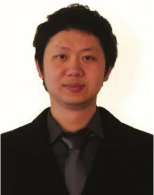
Mr. Cao Si-yang was born in Urumchi, China. He received the B.S. degree in electronic and information engineering from Xidian University, Shaanxi, China, in 2007, and the M.S. degree in circuits and system from South China University of Technology, Guangdong, China, in 2010. He is currently working toward the Ph. D. degree in the Department of Electrical and Computer Engineering at The Ohio State University, Columbus, Ohio, USA. His research interests include radar waveform design, synthetic aperture radar, cognitive radar, and signal processing with emphasis on radar signals.
E-mail: cao.151@osu.edu

Professor Zheng Yuan-fang was born in Shanghai, China. He studied as a graduate student at the Institute of Electronics, Chinese Academy of Science from 1978 to 1979. He then studied and received the M.S. and Ph.D. degrees in Electrical Engineering from The Ohio State University, Columbus, Ohio, USA in 1980 and 1984, respectively. Professor Zheng received his B.S. degree from the Tsinghua University in Beijing, China in 1970. From 1984 to 1989, he was with the Department of Electrical and Computer Engineering at Clemson University, Clemson, South Carolina. Since August 1989, Professor Zheng has been with The Ohio State University, where he is currently Winbigler Professor and served as the Chairman of the Department of Electrical and Computer Engineering from 1993 to 2004. Between 2004 and 2008, Professor Zheng served as Dean, on a part-time basis, of the School of Electronic Information and Electrical Engineering of the Shanghai Jiao Tong University in Shanghai, China. Professor Zheng received the Presidential Young Investigator Award from Ronald Reagan in 1986, and was elected to IEEE Fellow in 1997. His research interests are in wavelet based image processing and radar waveform studies, and sensor integrated robotic systems.
E-mail: zheng.5@osu.edu
雷达波形研究发展现况与趋势
曹思扬 郑元芳
(俄亥俄州立大学电子与计算机工程系 美国哥伦布 OH43210)
高速数字处理器技术与微波固态功率放大器技术的发展使得现代雷达系统采用更加灵活的波形设计变得可行。事实上,波形的选择对雷达系统的整体性能有着巨大的影响。该文回顾了传统的雷达波形设计技术,阐述了包括基于小波波形在内的针对新一代雷达设计的波形,并且分析了新一代雷达波形设计技术如何支持更加灵活多变的应用。该文尝试展示一个这样的事实,为了改善检测性能,雷达波形设计在针对特殊的用途(包括雷达测距和测速)中变得更加重要,从而改进雷达系统的性能和应用范围。
雷达波形;脉冲压缩波形;相位编码波形;多输入多输出(MIMO)雷达;小波
TN958
A
2095-283X(2014)05-0603-19
10.3724/SP.J.1300.2014.14044
Manuscript received March 10, 2014; revised April 16, 2014. Published online May 29, 2014.
Supported by the U.S. National Science Foundation and the Ohio State University.
*Corresponding author: Zheng Yuan-fang
E-mail: zheng.5@osu.edu
