Simulation of Reactive Distillation Process for Monosilane Production via Redistribution of Trichlorosilane
2014-07-24SunShuaishuai孙帅帅andHuangGuoqiang黄国强
Sun Shuaishuai (孙帅帅) and Huang Guoqiang (黄国强)
School of Chemical Engineering, Tianjin University, Tianjin 300072, China
Simulation of Reactive Distillation Process for Monosilane Production via Redistribution of Trichlorosilane
Sun Shuaishuai (孙帅帅) and Huang Guoqiang (黄国强)*
School of Chemical Engineering, Tianjin University, Tianjin 300072, China
The reactive distillation process for producing high purity monosilane via trichlorosilane redistribution reaction was simulated. Rigorous RadFrac block was employed in Aspen Plus simulation package. Accurate results could be given when the chemical kinetics was taken into account in the equilibrium stage model. A single column process was used for the verification of previous studies. The results showed that 99.9% purity monosilane could be achieved in the reactive distillation. A pumparound block was employed to reduce the condenser duty with inexpensive coolant. The effects of operating pressure, feed stage location, liquid holdup per stage and pumparound location were also investigated. The energy consumption was limited, but the refrigerant temperature was too low, which is the fatal disadvantage. Therefore, a double columns process was developed to increase the condenser temperature. The simulation results demonstrated that a reasonable temperature could be achieved by varying the recycle stream location.
reactive distillation, reaction kinetics, trichlorosilane redistribution, pumparound, monosilane
1 INTRODUCTION
In recent years, more attention has been paid to the renewable energy, especially solar energy, with the depletion of fossil energy. Polysilicon is the key material for the photovoltaic applications. Growing photovoltaic applications increase demand for the polysilicon.
The monosilane process uses monosilane as intermediate product to synthesize polysilicon. In the process, a continuous redistribution of trichlorosilane via dichlorosilane and monochlorosilane is employed to produce monosilane and silicon tetrachloride. The redistribution reaction equations [1] are
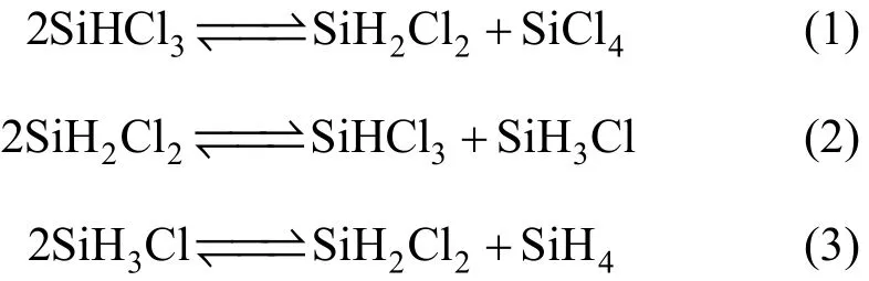
The three reactions are reversible, so two reactors and three or more columns are necessary for producing monosilane in conventional processes. Large amounts of unreacted reactants are separated and recycled for further reaction, so that energy and equipment costs are quite large.
Reactive distillation [2-6], which integrates the functionality of distillation and reaction, is a favorable alternative to conventional reaction-distillation processes. Reactive distillation processes save capital costs by using less equipment such as reactors and columns, and reduce the operating costs because the continuous separation of product in the reaction zone can break chemical equilibrium and approach 100% conversion.
The reactive distillation process for producing monosilane was first proposed by Bakay [7]. Afterward, many inventors concentrated on the design and improvement of the process. Block et al. [8] installed an intermediate condenser above the reaction zone to reduce the requisite amount of the low-temperature refrigerant and increase the concentration of monosilane by partial condensation of the higher-boiling components. Muller et al. [9] inserted the intermediate condenser in reaction area. Since heat removal will reduce reaction temperature and reaction efficiency, the key problem is how much heat should be removed. Sonnenschein et al. [10] disclosed a heat integration method for reactive distillation process. The reactive distillation column had double walls especially at the reaction zone and below. The bottom product containing SiCl4was conveyed via a heat exchanger to preheat the feed stream, and then into the double walls to transfer the additional heat to the catalyst to achieve the target temperature. Thus it can make full use of energy and get monosilane with purity of 99.5%.
Muller et al. [11] evaluated the economic aspect for the monosilane reactive distillation process. The equipment cost was reduced by 45% and energy cost was reduced by 60% compared to conventional cases. Thus the reactive distillation process has a significant economic benefit.
Only a few patents are related to reactive distillation processes for monosilane production. Although the primary problem is the particularly low refrigerant temperature, previous studies just considered how to reduce the amount of low-temperature refrigerant rather than increase its temperature. Moreover, the simulation of Muller [11] is based on the equilibrium stage model without the reaction kinetics considered, which disfavors the reliability of the results.
This paper focuses on the verification of previous studies by simulating a monosilane reactive distillation process in a single column process. The simulation is conducted with Aspen Plus and employs rigorousRadFrac block, which is based on an equilibrium stage model. The chemical kinetics is taken into account in the equilibrium stage model, which can give accurate simulation results. 99.9% purity monosilane is the objective. A pumparound block is employed for energy saving with inexpensive cooling agent. Then a double columns process is developed to increase the refrigerant temperature.
2 CHEMICAL KINETICS AND EQUILIBRIUM
With the increase of hydrogen content in chlorosilane molecules, the reaction rate increases. Reaction (1) is the control step for the overall redistribution reaction, and Reactions (2) and (3) can be assumed as instantaneous reaction.
The study [12, 13] showed that the redistribution reaction of trichlorosilane to dichlorosilane [Eq. (1)] in a DOWEX MWA-1 catalyst fixed-bed is a secondorder reversible reaction. The kinetic data is provided by Li and Huang [12]. The forward and backward reaction rate constants k+and k−can be expressed as
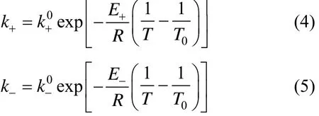
where T is the temperature given in K and T0is 353 K;andare the pre-exponential factors, being 3.01×10⁻⁴L·mol−1·s−1and 1.86×10⁻²L·mol−1·s−1, respectively; E+and E−are the activation energies, being 36.07 kJ·mol−1and 29.62 kJ·mol−1, respectively.
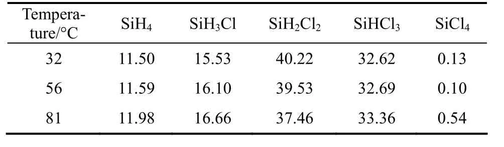
Table 1 Equilibrium composition in the redistribution of dichlorosilane
The kinetic data of Reactions (2) and (3) are not available, but equilibrium data [14, 15] listed in Table 1 can be used instead. When the redistribution reactions reach equilibrium, the chemical equilibrium constants can be solved by the following equations,
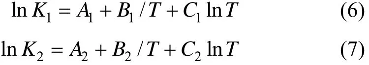
where K1and K2are the chemical equilibrium constants for reactions (2) and (3), respectively; Ai, Biand Ciare empirical coefficients, i=1, 2. The coefficients in Eqs. (6) and (7) are presented in Table 2.
The equilibrium stage model is based on phase equilibrium and reaction on each stage. The reactionon each stage is described by the reaction kinetics of Eq. (1) and the chemical equilibrium of Eqs. (2) and (3). The model is applicable to predict the results of reactive distillation process.

Table 2 Coefficients in Eqs. (6) and (7)
3 SIMULATION OF REACTIVE DISTILLATION PROCESS
3.1 Problem specification
Because of the limitation of chemical equilibrium, a variety of chlorosilanes and monosilane exist in the column. The boiling points [16] of chlorosilanes and monosilane are shown in Table 3. It is favorable for purifying monosilane, due to the significant difference in boiling points between monosilane and chlorosilanes. 99.9% purity monosilane can be easily achieved from a single distillation. However, the normal boiling point of monosilane is particularly low, which requires low temperature refrigerant to condense the vapor stream.
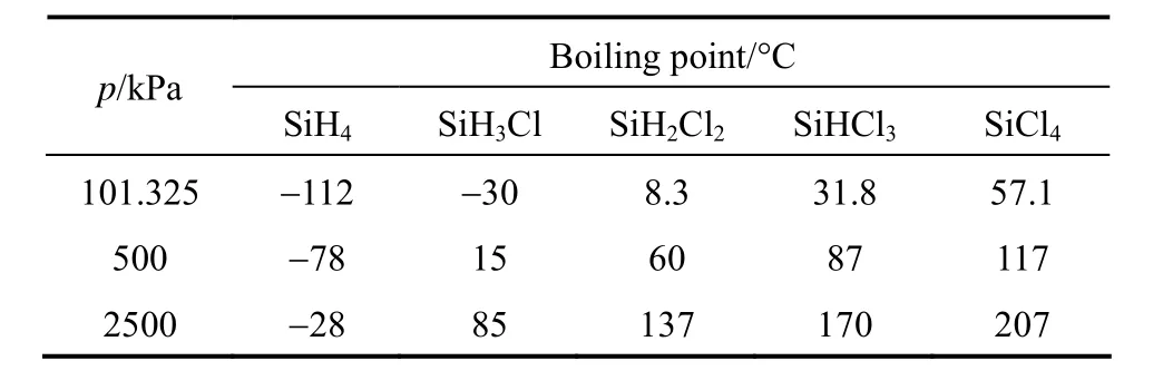
Table 3 Boiling points of chlorosilanes and monosilane
3.2 Column configuration

Figure 1 Single reactive distillation column

Table 4 Inputs of feed conditions and column specifications
A reactive distillation column (as shown in Fig. 1) was employed for the continuous redistribution of trichlorosilane, using catalyst DOWEX MWA-1. The column consists of 60 theoretical stages, with 15 rectifying, 30 reactive and 15 stripping stages. The chemical reactions are assumed to occur in the liquid phase only. The total effective liquid holdup is 300 L, evenly distributed among the reaction trays. A total condenser and a total reboiler are employed. The specifications and operating conditions of the reactive distillation column are shown in Table 4. The reactive distillation process is simulated with rigorous distillation model provided by Aspen Plus software. Chemical kinetics and equilibrium data mentioned above are used in the simulation. The purpose is to achieve monosilane with purity of 99.9%.
3.3 Simulation results
The reflux ratio is varied to achieve the specifications. The simulation results are presented in Table 5. The condenser temperature is extremely low and the reflux ratio is very large, so large amounts of very expensive low-temperature refrigerant are required to condense the overhead vapor. Compared with the refrigerant, the heating medium in the reboiler is easier to obtain. Therefore, the major operating costs are from refrigerant consumption. In addition, SiCl4is nearly 100% pure in the bottom, so a column is not needed for SiHCl3recovery. In conclusion, the reactive distillation process for monosilane production is feasible, and 99.9% purity of monosilane can be obtained.

Table 5 Simulation results for a single reactive distillation column
4 EFFECTS OF PARAMETERS
The reactive distillation is an integrated process, so its performance is influenced by various factors. The effects of pressure, feed stage, liquid holdup and pumparound are investigated, with monosilane purity fixed at 99.9%.
4.1 Effect of pressure
In conventional distillations, pressure is usually determined by the minimum temperature in the condenser where cooling water can be used or the maximum temperature in the reboiler to prevent thermal decomposition, while the pressure in a reactive distillation column is complexly determined by the interaction between reaction and separation.
In the reactive distillation column in this study, the reaction temperature should be controlled between 60 °C and 80 °C, limited by the catalyst activity. As shown in Table 3, the operating pressure should be below 500 kPa, so the condenser temperature is lower than −78 °C and the cooling agent may be a problem. The optimum conditions of pressure and temperature for reaction may be far from optimal conditions for distillation.
Figure 2 shows the temperature profiles of reaction zone obtained by changing the operating pressure from 300 to 400 kPa. The temperature increases steadily as pressure increases. Since redistribution reactions are endothermic and high temperature benefits it, 350 kPa is suitable for operating pressure. It is in accordance with the pressure suggested by Muller et al [9], which is between 200 and 500 kPa.
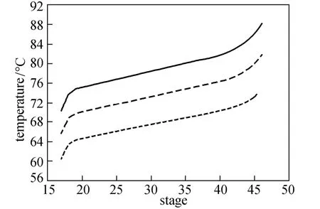
Figure 2 Effect of pressure on temperature at reaction zone
4.2 Effect of feed stage
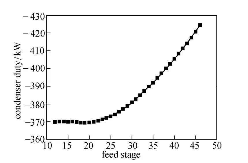
Figure 3 Effect of feed stage on condenser duty
Feed stage location is important in a reactive distillation, but was not investigated in the previous studies. Fig. 3 demonstrates that the feed stage has important effect on condenser duty. As the feed stage moves downward from the top to the bottom of the column, the duty of condenser changes little until reaching stage 19 and then increases steadily. The optimum feed stage is the 19th stage. When the feed stage locates at the bottom of the column, extra energy is required to prevent trichlorosilane escaping into the reboiler, removing larger amount of heat from the condenser.
4.3 Effect of liquid holdup
In conventional distillation design, liquid holdup has no effect on steady-state composition. In reactive distillation, liquid holdup has profound effects on conversion, product purity, and energy consumption, but it was not considered in previous study. Liquid holdup data for various packing can be found in literature [17-19]. Here, the simulation was conducted with the liquid holdup per stage varied from 4 L to 30 L, while keeping other parameters fixed.
Figures 4 and 5 show how boil-up and reflux rates change with the liquid holdup per stage. When the holdup is less than 4 L, the desired 99.9% purity of monosilane cannot be achieved with the given column configuration and operation conditions. The boil-up and reflux rates become very large near the holdup of 4 L. With the increase of liquid holdup, the boil-up and reflux rates decrease dramatically at the beginning and change little when the liquid holdup is greater than 10 L.
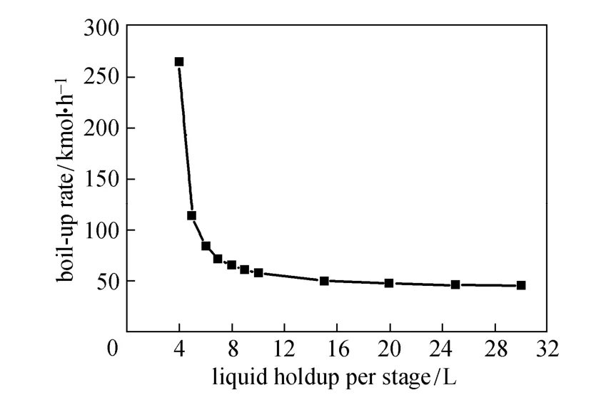
Figure 4 Effect of liquid holdup on boil-up rate
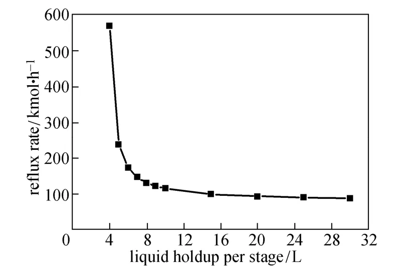
Figure 5 Effect of liquid holdup on reflux rate
The boil-up and reflux rates reflect the energy cost for operating the column. Larger liquid holdup can reduce the energy consumption, as shown in Fig. 6. Meanwhile, reaction rates depend on the liquid holdup, so more reactants will be converted per unit time as the liquid holdup increases [20]. With smaller liquid holdup, larger boil-up and reflux rates are provided to give more energy for separation to achieve the desired purity. Thus the condenser duty increases rapidly as the liquid holdup approaches 4 L.
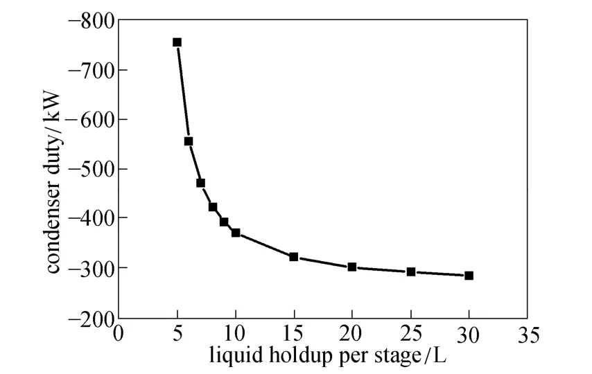
Figure 6 Effect of liquid holdup on condenser duty
4.4 Effect of pumparound location
The intermediate condenser referred by Block [8] and Muller [9] can remove most of heat at a significant higher temperature level compared to the top condenser temperature. The high boiling components, such as trichlorosilane and dichlorosilane, are condensed before escaping into the top condenser. In this paper, a pumparound block is employed for energy saving, which is built-in with Aspen Plus [21]. The boiling points of trichlorosilane and dichlorosilane are higher than 50 °C at 350 kPa, so cheap cooling water can be used to condense the ascending vapor in the column. The ascending vapor, withdrawn through a gas mass flowmeter at 40 kmol·h−1, is condensed to 30 °C liquid in an external heat exchanger, and then conveyed back to the column by a pump.
Figure 7 indicates that the draw and return stages vary for optimum condenser duty (QC), and Fig. 8 shows how pumparound affects the increment of reboiler duty (ΔQB) in three cases.
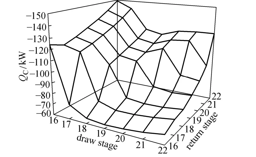
Figure 7 Effect of pumparound location on condenser duty
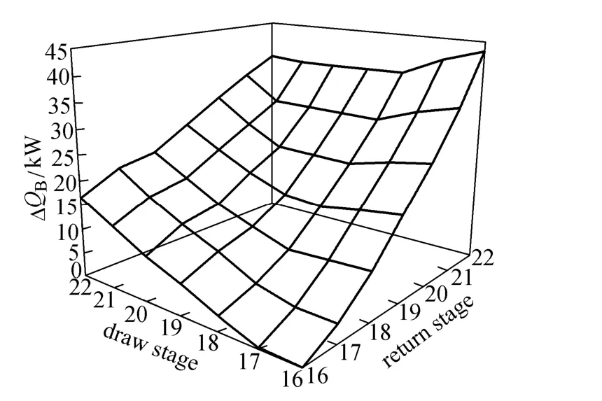
Figure 8 Effect of pumparound location on increment of reboiler duty
Case 1: The return stage is below the draw stage. It can reduce the condenser duty, but the back mixing of liquid may lead to large increment of reboiler duty as shown in Fig. 8.
Case 2: The return stage is at the draw stage. This case is considered by Block [8] and Muller [9] but only 3%-40% of the heat is carried away. The effect of energy saving is moderate based on the results shown in Fig. 7.
Case 3: The return stage is above the draw stage. It can significantly reduce the condenser duty, because the high boiling components in the ascending vapor are further condensed by low-temperature returning liquid. The heat carried away is between 65% and 80%, which is higher than that in Case 2. Moreover, it has little effect on the reboiler duty.
All the three cases can reduce condenser duty and increase reboiler duty, and the Case 3 is superior to the methods proposed by Block [8] and Muller [9]. The significant reduction of condenser duty in Case 3 can compensate for the limited increment of reboiler duty. Therefore, the optimum location is that the vapor is withdrawn at the 19th stage while the liquid returns at the 16th stage. The condenser duty here is −63.37 kW, reducing by 82.88% compared to the column without pumparound.
5 DOUBLE COLUMNS PROCESS
5.1 Process description
For the single column process, the operating and capital costs for producing refrigerant with extremely low temperature are very large. Thus the primary problem is how to increase the condenser temperature. It may be easier to achieve in industrial for a temperature above −50 °C. Therefore, a double columns process (as shown in Fig. 9) is developed for increasing the condenser temperature. The reactive distillation column is coupled with a high pressure distillation column for purifying monosilane. A liquid stream is withdrawn from the top of the first column and conveyed to the second column to produce high purity monosilane. The bottom product of the second column, containing unreacted reactants, is recycled to the first column.

Figure 9 Double columns process
In the reactive distillation column, the content of dichlorosilane, monochlorosilane and monosilane in distillate is specified at 99.9%, and the purity of silicon tetrachloride in bottom product is specified at 99.9%. Other specifications for the reactive distillation are as same as that in the single column process. The distillate rate and reflux ratio are varied to achieve the specifications. In the high pressure column, the operating pressure is set at 3 MPa. It consists of 7 stages and the feed stage is the 4th stage. The purity of monosilane in distillate is specified at 99.9%, and the distillate rate is 2.5 kmol·h−1.
5.2 Effect of recycle stream location
Different recycle stream locations result in different distillate compositions, and affect condenser temperature of the reactive distillation column. The results are shown in Fig. 10. The condenser temperature and heat duty profile show inflection point at the 18th stage. As recycle stream stage moves down from the 18th stage, the condenser temperature increases, while the duty of condenser and reboiler both increase gradually. As the recycle stream stage moves up from the 18th stage, the condenser temperature and dutyincrease rapidly, while the reboiler duty profile remains stable. The explanations are presented in Fig. 11 and Fig. 12.

Figure 10 Effects of recycle stream stage on reactive distillation column
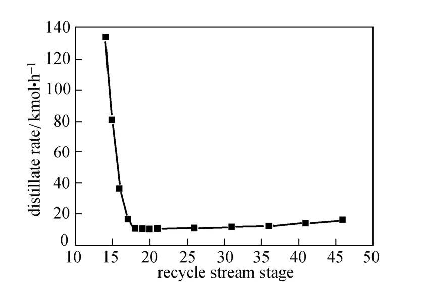
Figure 12 Effects of recycle stream stage on distillate rate
The recycle stream is almost same with the distillate excluding monosilane. As shown in Figs. 11 and 12, as the recycle stream stage moves down from the 18th stage, dichlorosilane is the largest proportion in distillate and increases steadily, so the condenser temperature increases. When monosilane is in some proportions in distillate and declines slightly, the temperature changes a little. Monochlorosilane and dichlorosilane in recycle stream inhibit main reactions in the reaction zone, so extra energy is needed to achieve the desired purity. As the recycle rate increases slowly, the duty of reboiler and condenser increase. As the recycle stream stage moves up from the 18th stage, the content of monochlorosilane in distillate increases dramatically, while the content of monosilane and dichlorosilane drop suddenly, so the condenser temperature increases significantly. Monochlorosilane in the recycle stream is mainly used to maintain high purity level in the condenser in order to increase the temperature, so the condenser duty increases suddenly while the reboiler duty remains stable.
When the recycle stream stage locates at the 14th stage, the condenser duty and distillate rate are extremely large. The process is difficult to converge. Therefore, the suitable recycle stream stage locates between the 14th and 18th stage.
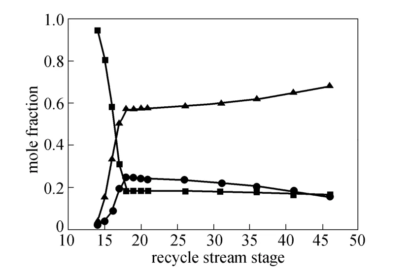
Figure 11 Effects of recycle stream stage on composition of distillate
6 CONCLUSIONS
In this paper, the reactive distillation process for producing monosilane via redistribution of trichlorosilane is simulated. Chemical kinetics is taken into account in the equilibrium stage model, which gives accurate simulation results. The results are well in accordance with foreign patents, so the study is a guide for the design of equipment and technology. Based on the study on a single column process, a double columns process is developed for increasing condenser temperature.
The simulation gives following results:
(1) It is feasible for the reactive distillation process to achieve 99.9% purity monosilane.
(2) The pumparound employed in the reactive distillation column can reduce energy consumption in the condenser by up to 82.88%. The optimum location of pumparound is determined, the vapor is withdrawn from the 19th stage and the liquid is returned to the 16th stage.
(3) The single column process consumes less energy, but the condenser temperature is extremely low,−86.92 °C.
(4) The double column process is appropriate to give suitable condenser temperature from −50 to −5 °C.
REFERENCES
1 O’mara, W.C., Herring, R.B., Hunt, L.P., Handbook of Semiconductor Silicon Technology, William Andrew, New Jersey (1990).
2 Luyben, W.L., Yu, C.C., Reactive Distillation Design and Control, John Wiley &Sons, Inc, New Jersey (2008).
3 Sundmacher, K., Kienle, A., Reactive Distillation: Status and Future Directions, Wiley-VCH Weinheim, Magdeburg (2003).
4 Luyben, W.L., Distillation Design and Control Using AspenTMSimulation, John Wiley & Sons, Inc, New Jersey (2006).
5 Taylor, R., Krishna, R., “Modelling reactive distillation”, Chem. Eng. Sci., 55 (22), 5183-5229 (2000).
6 Malone, M.F., Doherty, M.F., “Reactive distillation”, Ind. Eng. Chem. Res., 39 (11), 3953-3957 (2000).
7 Bakay, C.J., “Process for making silane”, US Pat., 3968199 (1976).
8 Block, H.D., Leimkuhler, H.J., Muller, D., Sch Fer, J.P., Ronge, G.,“Method and system for producing silane”, US Pat., 6905576 B1 (2005).
9 Muller, D., Ronge, G., SchaFer, J.P., Leimkuhler, H.J., Strauss, U., Block, H.D., “Method and facility for producing silane”, US Pat., 6942844B2 (2005).
10 Sonnenschein, R., Adler, P., Kasatkin, Y., Petrik, A., Schwarzmann, L., “Process for producing monosilane”, US Pat., 2009/0155156A1 (2006).
11 Muller, D., Ronge, G., Sch Fer, J.P., Leimkuhler, H.J., “Development and economic evaluation of a reactive distillation process for silane production”, In: International Conference on Distillation & Absorption, Kongresshaus, Baden-Baden, Germany (2002).
12 Li, K.Y., Huang, C.D., “Redistribution reaction of trichlorosilane in a fixed-bed reactor”, Ind. Eng. Chem. Res., 27 (9), 1600-1606 (1988).
13 Plahutnik, F., Arvidson, A., Sawyer, D., Sharp, K., “Development of a polysilicon process based on chemical vapor deposition (phase 1 & phase 2)”, NASA-CR-173957 (1982).
14 Breneman, W.C., Farrier, E.G., Morihara, H., “Feasibility of low-cost, high-volume production of silane and pyrolysis of silane to semiconductor-grade silicon”, NASA-CR-158585 (1978).
15 Kota, N.R., “Study of silane production”, Master Dissertation, Lamar University, Beaumont (2009).
16 Sonnenschein, R., Adler, P., Popken, T., Kahsnitz, J., “Apparatus and process for preparing silanes”, US Pat., 2008/0095691 A1 (2005).
17 Ratheesh, S., Kannan, A., “Holdup and pressure drop studies in structured packings with catalysts”, Chem. Eng. J., 104 (1-3), 45-54 (2004).
18 Moritz, Peter, Hasse, Hans., “Fluid dynamics in reactive distillation packing Katapak®-S”, Chem. Eng. Sci., 54 (10), 1367-1374 (1999).
19 Xu, X.E., Zhao, Z.H., Tian, S.J., “Study on catalytic distillation processes: Part Ⅲ: Prediction of pressure drop and holdup in catalyst bed”, Chem. Eng. Res. Des., 75 (6), 625-629 (1997).
20 Cai, J.L., Cui, X.B.,Yang, Z.C., “Simulation for transesterification of methyl acetate and n-butanol in a reactive and extractive distillation column using ionic liquids as entrainer and catalyst”, Chin. J. Chem. Eng., 19 (5), 754-762 (2011).
21 Kumar, S., “Modelling and simulation of ethyl acetate reactive distillation column using ASPEN PLUS”, Bachelor Thesis, National Institiute of Technology, India (2010).
SEPARATION SCIENCE AND ENGINEERING
Chinese Journal of Chemical Engineering, 22(3) 287—293 (2014)
10.1016/S1004-9541(14)60045-8
2012-08-05, accepted 2013-01-08.
*To whom correspondence should be addressed. E-mail: hgq@tju.edu.cn
杂志排行

Chinese Journal of Chemical Engineering的其它文章
- A Bi-component Cu Catalyst for the Direct Synthesis of Methylchlorosilane from Silicon and Methyl Chloride
- Hydrodynamics and Mass Transfer of Oily Micro-emulsions in An External Loop Airlift Reactor
- Effects of Shape and Quantity of Helical Baffle on the Shell-side Heat Transfer and Flow Performance of Heat Exchangers*
- A Contraction-expansion Helical Mixer in the Laminar Regime*
- Preparation and Characterization of Sodium Sulfate/Silica Composite as a Shape-stabilized Phase Change Material by Sol-gel Method*
- Determination of Transport Properties of Dilute Binary Mixtures Containing Carbon Dioxide through Isotropic Pair Potential Energies