Analysis of delay effects and design of output filter for IFOG
2014-07-20WEIYan
WEI Yan
(Shanghai Institute of Spaceflight Control Technology,Shanghai 200233,China)
Analysis of delay effects and design of output filter for IFOG
WEI Yan
(Shanghai Institute of Spaceflight Control Technology,Shanghai 200233,China)
The delay of the digital circuit of an IFOG is inevitable,which will result in the noises in the output data and reduce the accuracy of the IFOG.In order to solve the problem,the effects of the delay of the digital circuits to the nonlinearity of the output of the IFOG are discussed,and the method of improvement in designing the digital circuits is recommended.The design of the output filters for reducing the noise from nonlinearity of D/A is put forward,and some of the attentions are also pointed out when changing the type of the average or using the filters other than an average.The purpose of elimination of the effect of the delay is obtained with the proposed design.The simulation shows that the SD of the noise in the output data due to the delay can be limited to zero.
IFOG;delay;filter;average;nonlinearity
The closed-loop IFOG (Interferometric Fiber-optic Gyroscope) has been developed for many years and it has been put into the application in many fields[1-4].In many cases,an IFOG with high performances is pursued with help of Kalman Filter or Wavelet Filter[5-7].The accuracy and dynamics are both criterion for the application.Duo to the limit of the bits of the D/A in the IFOG,nonlinearity will occur in the output data,which will also result in noises.The delay in the digital circuit will worsen the nonlinearity.The output filter is a very important method to smooth the noise,and is truly an efficient way,if properly designed.
In the reference [8],the characteristic of D/A was discussed,but the nonlinearity resulted was not researched further.In the reference [9],the design of the controller and the output filter was discussed,but the effects of the delay were not considered.In this paper,the focus will be on the effects of the delay and the output filter,and the design suitable for the engineering application is also put forward.
1 The modeling of the IFOG
The closed-loop IFOG is made of SLED,PINFET,fiber optic coil,IOC,electronic circuits and etc.The main purpose of the IFOG is to measure the vector of the rotation speed of the carrier refer to the inertial space.It transfers the rotation speedΩininto the Sagnac phaseΦsagby the Sagnac interferometer and outputs the dataΩoutrepresenting the input rotation speed.The circuits detect the difference between the Sagnac phaseΦsagandthe feed-back phaseΦf,and then calculate the output dataΩoutwhich generates the next feed-back phaseΦf.
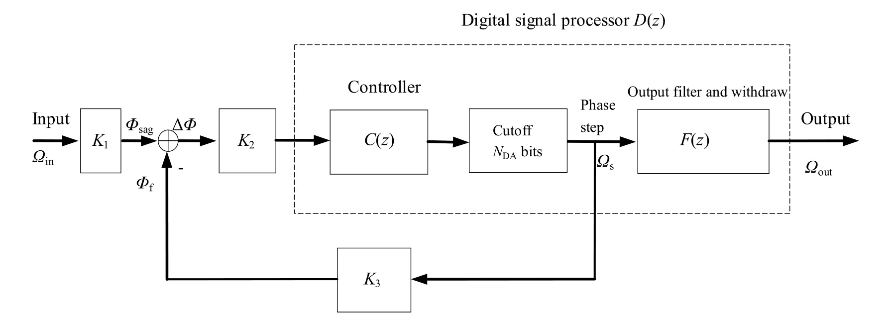
The main principle outline is shown in Fig.1.

Fig.1 The outline of the IFOG
In Fig.1,Ωinis the input of the rotation speed;Φsagis the Sagnac phase;Φfis the feed-back phase;Φbis the phase of a square wave bias;ΔΦis the sum of theΦsag,-ΦfandΦb;Ωsis the phase step of the digital phase ramp;Ωoutis the output of the IFOG;τis the propagation time of the light in the fiber optic coil.
The Sagnac effect is a linear transformation and can be regarded as a proportional coefficientK1.The function of the detector biased by ±π/2,pre-amplifier,sample and demodulator can be simplified by a proportional coefficientK2,assuming that ΔΦis a small quantity.The function of phase modulator and the phase ramp with D/A convertor and zero-order holder is countervailed,thus the feed-back loop can be simplified as a coefficientK3.The simplified model of the IFOG is shown in Fig.2.

Fig.2 The simplified model of the IFOG

Fig.3 The control signal scheme of the IFOG
The main designing work for the digital signal processorD(z) is to design the controllerC(z) and the output filterF(z).Usually,an integrator is adopted as the controller and an average as the output filter,as shown in Fig.3.The transfer function of the digital integrator is,and the average,whereais the coefficient of the integrator,kthe delay of the digital signal andmthe length of the average.The closed-loop transfer function of the phase stepΩs(z) to the inputΩin(z) is

The steady output of the phase stepΩsfor the constant inputΩinis

Because the digital bits of a D/A convertor available is limited,such asNda,the output data of the integrator withNcbits have to be cutoff byNdabits and discard the excessive bits of the data by right shifting operation of the register to generate the phase stepΩs,which will result in the nonlinearity of the output data for the small input of the rotation speed[10].
If the constant inputΩinis precisely equal toK3/K1,there will be no problem for the controller to generate the phase stepΩsas “1” through the feedback control and have a steady output.If the inputΩinis precisely equal to half ofK3/K1,the controller has to generate the phase stepΩsas “1” and “0” periodically in a steady way.If the inputΩinis precisely equal to 2-nK3/K1,the controller has to generate the phase stepΩsas one “1” and 2n-1 continuous “0” periodically in a steady way,which will result in nonlinearity in the output data tremendously and the noise as well.The solution to the above problem is to average the phase stepΩs,which is the basic reason why the output filter uses an average of 2ndata to smooth the periodic phase stepΩsof one “1” and 2n-1 continuous“0”.That will guarantee the resolution of the closed-loop IFOG usually.
2 The analysis of the effects of the delay
As usual,the effects of the delay of the digital signal are negligible,because the delay time is too short to affect the dynamics of the system.Nevertheless,some of the considerations have to be taken into.
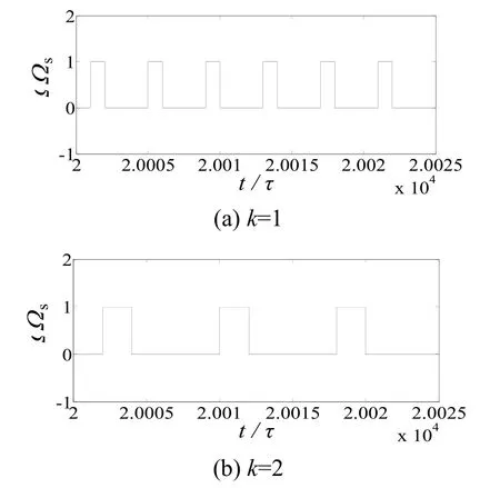
If we need a resolution of quarter ofK3/K1for the closed-loop IFOG,a constant input of quarter ofK3/K1will make the controller to generate the phase stepΩsas one “1” and three continuous “0” periodically in a steady way,and an average of 4 data is enough for smoothing the noise due to the nonlinearity of the D/A.All these are under the consideration that the delaykis equal to 1.If the delaykis equal to 2,the controller will generate the phase stepΩsas two continuous “1” and six continuous“0” instead of one “1” and three continuous “0”periodically in a steady way,which need an average of double length to obtain the accurate steady outputΩout.Fig.4 shows the simulation of the phase stepΩswith different delayk.That will be a great disaster for the IFOG of the resolution of one thousandth ofK3/K1with the delaykgreater than 2,because the steady period of the phase stepΩswill be more than 2 thousand data.

Fig.4 The simulation of Ωs for the different delay k
In general,the delay of the digital circuit is inevitable.One of the solutions to the problem above is to lengthen the data of the average,which will reduce the dynamic band width of the IFOG.Another way is to improve the designing of the digital circuit to limit the delaykto 1.Using a higher frequent pulse for the working reference is a good idea,such as the pulse for the sample which is much higher than the eigen frequency of the IFOG.
3 The design of the output filter
In the least structure of a closed-loop IFOG,there is no need of the output filter and the phase stepΩswill be the final output.Certainly,the resolution of the IFOG is limit to that of the D/A,which cannot meet the needs of the engineering application.In order to get higher resolution and reduce the noise duo to the nonlinearity of D/A at the same time,an average of lengthmis adopted as the output filter.The digital transfer function of the output filter is

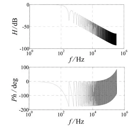
Usually,the lengthmof the average is about the type of 2n.A filter of 211long is recommended for the IFOG of the resolution of 2-10K3/K1and the delay of 2,the SD (Stand Deviation) of which is about zero.Ifτis equal to 1.5 μs,the band width of the filter above will greater than 100 Hz and the dynamic frequency spectrum of the filter are illustrated in Fig.5.

Fig.5 The frequency spectrum of the output filter
Any changes of higher resolution than 2-10K3/K1and more delay than 2,the length of the filter above cannot cover the steady data period of the phase stepΩsand the steady output of the filter will result in the noise,which will affect the steady characteristic of the IFOG.
The change of the structure of the average is not recommended,especially the reduction of the length of the average.For example,for the purpose of faster decline speed of the magnitude of the spectrum in the high frequency band,a usual design is to reduce the length of the average and increase the stage of it.For example,instead of an average of 4 data,a filter of two stage of an average with 2 data is designed for an IFOG of the resolution of 2-2K3/K1,where the delaykis equal to 1.The digital transfer function of the filter isF(z),as follows.

If the inputΩinis precisely equal to 2-2K3/K1,the filter will not output the steady accurate data of 0.25 with the SD of zero,but the steady data of 0,0.25 and 0.5 in an uncertainty way with the SD of 0.204.The transfer functionF(z) above can be expressed as follows

The function of the filter above is not an average any longer,but a kind of FIR (Finite Impulse Response) filter.Then,we have to be careful to reduce the length of the average or deal with any filter other than an average,such as IIR (Infinite Impulse Response) filters,FIR filters and etc.
4 Conclusion
The delay in the design of a digital circuit is inevitable and will worsen the nonlinearity of the D/A.The best way to overcome the problem is to limit the delaykto less than 2 or select other reference pulse with higher frequency.
In order to obtain a good resolution of the closed-loop IFOG,an average as an output filter has to be adopted to smooth the data of the phase stepΩs.The length of the average must not less than the period of the data of the phase stepΩs,otherwise the SD of which will not trend to zero.More attention has to be paid when other kinds of filters are dealt with,which have not any function of the average at all.
[1]Udd E.A personal tour of the fiber optic Sagnac interferometer [C]//Proc.of SPIE,Vol.7316 73160R,2009.
[2]Pavlath G A.Fiber Optic Gyros Past,Present,and Future[C]//OFS2012 22ndInternational Conference on Optical Fiber Sensors.Proc.of SPIC,Vol.8421 842102,2012.
[3]Korkishko Y N,Fedorov V A,Prilutskii V E,et al.Interferometric closed-loop fiber-optic gyroscopes[C]//Third Asia Pacific Optical Sensors Conference.Proc.of SPIE,2012,Vol.8351:83513L.
[4]Zhang Chunxi,Song Ningfang,Li Lijing,et al.Fiber optic gyro R&D at Beihang University [C]//OFS2012 22ndInternational Conference on Optical Fiber Sensors.Proc.of SPIC.2012,Vol.8421:842105.
[5]Wu Xingming,Duan Li,Chen Weihai.A Kalman filter approach based on random drift data of fiber optic gyro[C]//2011 6thIEEE Conference on Industrial Electronics and Applications.IEEE 978-1-4244-8756-1/11,2011.
[6]Yuan Rui,Song Ningfang,Zhang Guohua,et al.Autonomous detection of angle random walk and quantization noise of fiber optic gyro in attitude determination system of satellite[J].IEEE Sensors Journal,2013,13(1):211-216.
[7]CHENG Jianhua,LI Mingyue,RONG Wenting,et al.Research and realization of real-time wavelet filter algorithm for shipborne FOG[C]//Proceedings of the 2011 IEEE International Conference on Mechatronics and Automation.Beijing,China,August 7-10,2011.
[8]金靖,宋凝芳,张春熹.光纤陀螺高速检测电路设计[J].中国惯性技术学报,2002,10(2):49-53.JIN Jing,SONG Ning-fang,ZHANG Chun-xi.Design of high speed detection circuit for fiber-optic gyroscope[J].Journal of Chinese Inertial Technology,2002,10(2):49-53.
[9]王妍,张春熹,刘镇平.闭环光纤陀螺数字控制器的设计与仿真[J].光电工程,2004,31:108-113.WANG Yan,ZHANG Chun-xi,LIU Zhen-ping.Design and simulation of a digital controller for closed-loop fiber optic gyroscopes[J].Opto-Electronic Engineering,2004,31:108-113.
[10]朱明达,宋凝芳,潘雄,等.太空单粒子效应光纤陀螺输出地面模拟分析[J].中国惯性技术学报,2013,21(1):120-124.ZHU Ming-da,SONG Ning-fang,PAN Xiong,et al.Simulation analysis on FOG output under space single event effect[J].Journal of Chinese Inertial Technology,2013,21(1):120-124.
1005-6734(2014)03-0396-04
10.13695/j.cnki.12-1222/o3.2014.03.022
光纤陀螺延迟影响分析及输出滤波器设计
卫 炎
(上海航天控制技术研究所,上海 200233)
干涉式光纤陀螺的电子线路中不可避免会产生延迟,使得输出增加噪声并影响陀螺精度。为了解决上述问题,讨论了光纤陀螺数字电路的延迟对输出的非线性影响,并提出了相应的改善其影响的设计方法。另外对于为了减小数模转换器非线性噪声而增加的输出滤波器,也进行了设计,并同时指出了改变平均算法形式或使用平均算法以外的滤波器时应注意的事项。通过精心设计,可以达到彻底消除延迟影响的目的。仿真结果表明由于延迟引起的输出噪声标准差可以限制到零。
光纤陀螺;延迟;滤波器;平均算法;非线性
U666.1
A
2014-02-23;
2014-05-14
卫炎(1960—),男,研究员,从事光纤陀螺研究。E-mail:yanw2008@aliyun.com
