Aircraft Electric Anti-skid Braking System Based on Fuzzy-PID Controller with Parameter Self-adjustment Feature*
2014-04-24WeiXiaohui魏小辉YinQiaozhi尹乔之NieHong聂宏ZhangMing张明TaoZhouliang陶周亮
Wei Xiaohui(魏小辉),Yin Qiaozhi(尹乔之),Nie Hong(聂宏)Zhang Ming(张明),Tao Zhouliang(陶周亮)
State Key Laboratory of Mechanics and Control of Mechanical Structure,Nanjing University of Aeronautics and Astronautics,Nanjing,210016,P.R.China
1 Introduction
Electric braking system is an irresistible development trend of the aircraft braking system at present.Because of its complicated non-linear behavior,the selection of control law is of great importance,which has a bearing on the performance of the whole system.So according to the features of the electric braking system,it is necessary to improve the anti-skid control method of the braking system to achieve the best possible braking efficiency.
Nowadays,most of the anti-skid control systems which have been put into use in domestic apply the sliding velocity control system[1](using pressure-bias-modulated(PBM)),while several commercial and military jet aircrafts in Europe use slip rate control braking system[2].In comparison,the efficiency of the sliding velocity control system is higher[3-6].As the theory of control developing,intelligent control has been more and more widely applied into practical engineering,which brings a new idea to design the control law of aircraft braking system.Some new control theory,like fuzzy control[7],neural network control[8],optimum control[9],and nonlinear control[10]has all been used to design the anti-skid law.
According to the algorithm of fuzzy-proportional-integral-derivative(PID)control with parameter self-adjustment feature,the anti-skid law of the electric braking system is designed in this paper.At the same time,the braking performance is simulated in the cases of dry runway and wet runway to verify the advantages of the electric braking system,as well as the high efficiency of the control law.
2 Electric Braking System Based on Slip Rate Control
The definition of the slip rate is the relative slippage between the wheel and the road.Its expression can be shown as follows

whereσis the slip rate,vxthe heading landing speed of the aircraft,and vrthe linear velocity of the wheel.
The slip rate has the greatest influence on the friction coefficient.Therefore,the braking system should control the slip rate on the optimal value in order to keep the friction coefficient maximal and to achieve the highest efficiency of braking.

Fig.1 Schematic diagram of electric braking system
The aircraft electric braking system contains five parts below:Electromechanically actuated(EMA)braking frame,wheel speed sensor and its bracket,torque transducer and its bracket,EMA controller,and B/S controller.The operating principle is:The signal of wheel speed and brake torque is transmitted to B/S controller through the wheel speed sensor and the torque transducer.The signal generated by B/S controller is then imported to EMA controller,which will produce control signal to control EMA mechanism.This EMA mechanism exports brake pressure on brake disc to generate the corresponding brake torque.As a result,electric braking system is the double-negative-feedback closed-loop control system based on the wheel speed and the brake torque.Fig.1shows its working principle.
3 Fuzzy-PID Controller with Parameter Self-adjustment Feature
3.1 Basic ideas of fuzzy-PID control algorithm
The fuzzy-PID control system with parameter self-adjustment feature[11]is an adaptive control system which uses the fuzzy control rule to modify the PID parameters online.It is able to realize better dynamic and steady-state performance for nonlinear time-varying system.
The control signal of the conventional digital PID adjuster is

where U(k)is the output of PID controller,Kpthe proportionality coefficient of the PID controller,KIthe integral coefficient,KDthe differential coefficient,E(k)the closed-loop deviation,and E(k-1)the closed-loop deviation at the last time.
The fuzzy-PID controller applies the fuzzy set theory to establish the functions of KP,KI,KD,deviation absolute value|E|,and deviation change|EC|based on the regular PID controller,shown as

KP,KI,KDcan be adjusted online according to different|E|and|EC|.
3.2 Modeling of fuzzy-PID controller with parameter self-adjustment feature
The model of the fuzzy-PID controller with parameter self-adjustment feature is established with MATLAB/SIMULINK.From the above analysis,the electric braking system contains not only the velocity feedback,but also the feedback of brake torque,of which the brake torque is on the inner loop,and the slip rate is on the outer loop.The control block diagram of the whole braking system is shown in Fig.2.
Due to the double-close-loop control,the control parts consist of the slip rate and the brake torque.The design of the fuzzy-PID control above mainly targets the control of the slip rate.However,the control of the brake torque uses traditional PID control method,aiming to generate the signal to adjust the rotating speed of DC motor according to the difference of the brake torque between the input and the actual values,which can make the actual brake torque track the target value.Thus the model of the braking controller of the electric braking system is established.

Fig.2 Control block diagram of electric braking system
4 Aircraft Ground Taxiing Model
When the aircraft is taxiing on the ground,the forces on the aircraft are:Gravity,motor power,aerodynamic force(including lift,drag),ground reaction force and friction force[12]on the wheels,and the moment produced by the forces.The force analysis of airplane movement on the ground is shown in Fig.3.
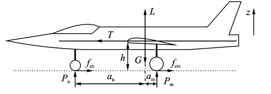
Fig.3 Force analysis of airplane movement on ground
The external resultant force and the moment in the ground axis system are

where Tis the motor power.Dand Lare the air drag and the lift respectively,Qn,Qmthe friction forces to the nose wheel and one of the main wheel respectively,Pn,Pmthe ground reaction forces to the nose wheel and one of the main wheel.Gis the gravity,anthe projection distance between the nose wheel and the gravity center of the aircraft,amthe projection distance between the main wheels and the gravity center of the aircraft,mthe weight of the aircraft,MTthe moment of the motor,Ibthe moment of inertia of the aircraft,andθthe pitch angle.
5 Model of Electric Differential Braking System
5.1 Model of EMA mechanism
The EMA mechanism is composed of brushless DC motor,harmonic reducer and ball screw[13].The inertia moment,the driving moment and the drag torque of the ball screw are the important bases in selecting the motor capacity when the system is designed.
The load torque of the motor is

where TMis the load torque of the motor,˙ωhthe angular acceleration of the ball screw,JMthe rotational inertia,and TLthe part of load torque of the motor caused by ball screw and drag torque.
The motor drives the ball screw to change rotational motion to rectilinear motion of the nut,which will push the pressure plate against the brake disc.So the formula is

whereωhis the rotational speed of the ball screw,l the axial displacement of the datum point of the nut.
The revolving speed and current feedback direct current governor system is composed of DC motor and motor controller,which has nice static and dynamic performance[11].The revolving speed and current close-loops are both adjusted by PI controller.The voltage and current of the circuit are shown as

where Tlis the electromagnetic time constant of armature loop,Rathe armature resistance,Eathe counter electromotive force of the motor,ial(t)the load current,and Tmthe electromechanical time constant.
According to the transfer function of PWM power electronic converter and the calculation of the feedback factors,the mathematical model of the direct current governor system[14]is shown in Fig.4.

Fig.4 Mathematical model of direct current governor system
5.2 Model of brake apparatus
The main effect of the brake apparatus is to change braking thrust into braking torque as well as to consume the kinetic energy of the aircraft.
The braking thrust Stis in proportion to the compact distance lapproximately,which is shown as follow

where Ktis the proportionality coefficient.
The braking torque can be derived according to the braking force,shown as

whereμmcis the friction coefficient,Nmcthe numbers of the friction faces,Rtthe external radius of the stators,and rtthe internal radius of the rotors.
近年来,高邮市以阿里巴巴农村淘宝项目为抓手,整合资源、强化合作,进一步推动农业信息化建设快速发展,切实提升为农信息服务水平,促进农民增收致富。2017年,全市新增农业物联网技术应用示范点1个、益农信息社175个、农业电商企业13个,农业电商销售达5.9亿元。高邮市获批江苏省农业电子商务示范县,成功跻身阿里巴巴全国农产品电商50强县(市),是扬州市唯一入围的县市,高邮特产馆被团中央与京东集团联合授予青年电商创业孵化中心。
However,the brake pair not only usually suffers deformation during mechanical wear and temperature variation,but is also required to be separated after braking thrust relieving.Therefore,the function relationship between the braking torque and braking thrust has a dead zone.This function curve can be expressed by tri-linear hysteresis model.The empirical Eq.(11)is used when modeling.


where Msmis the largest braking torque,M1the last braking torque,P0the pressure loss of the hysteresis,Pxthe largest pressure lag,Pmaxthe largest braking thrust,and rPthe last braking thrust.
5.3 Model of aircraft wheels
When the aircraft is taxiing on the ground,there is friction force between the braking wheels and the ground.The product of this friction force and the rolling radius of the braking wheels is the braking torque.The rolling of the wheels is controlled by both the friction torque and the braking torque which can be expressed as follows

whereωand˙ωare the angular velocity and the angular acceleration.Mjis the friction torque,Mbthe braking torque,Jrthe rotational inertia of one wheel,vrthe linear velocity of the wheels,and Rgthe radius of the wheels.
The factors which affect the friction torque of the braking wheels include:The vertical load on the braking wheels,the rolling radius of the braking wheels,and the friction coefficient between the tires and the ground.The formula is shown as

whereμis the friction coefficient between the tires and the ground,Pmthe vertical load on the main wheels,and nthe number of the main tires.
6 Simulation and Analysis
In conclusion,the whole model diagram of the slip rate electric braking system is shown in Fig.5.
If the control system has the PID-controller only without the fuzzy-PID controller,the simulation curves in the dry runway case are shown in Fig.6.From the simulation results,anti-skid braking lasts 16.9sand the distance of landing run is 723msince the brake starts when the wheel reaches the maximum velocity till the aircraft stops with the zero speed.
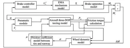
Fig.5 Whole model diagram of slip rate electric braking system
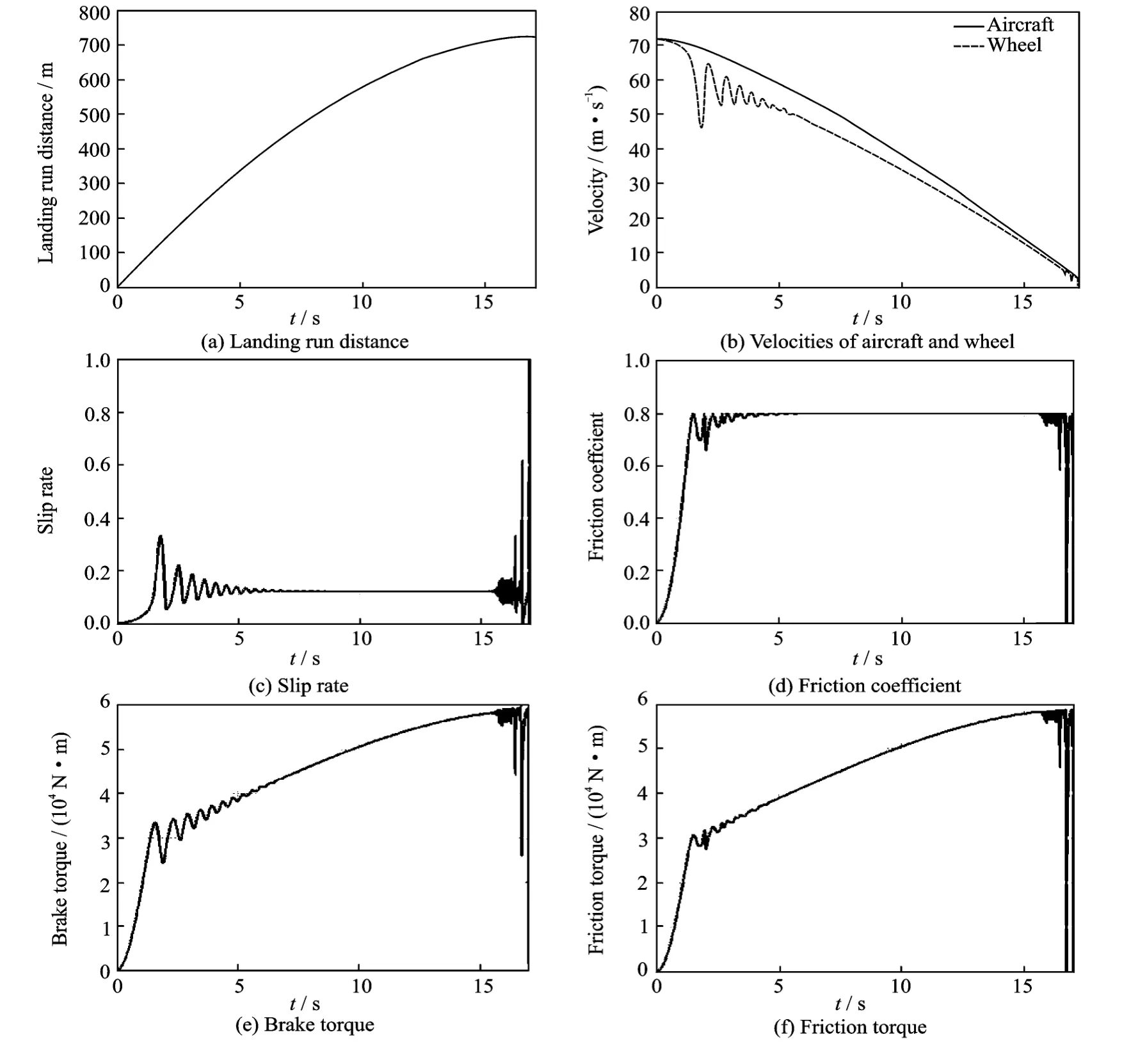
Fig.6 Simulation curves in dry runway case with PID-controller only
However,if the control system has the electric anti-skid braking system based on the fuzzy-PID controller with parameter self-adjustment feature,the simulation curves in the dry runway case are shown in Fig.7.During the whole process,the slip rate maintains at the best with the value around 0.12all the time.The braking efficiency is calculated as 93%according to the friction coefficient.
Compared with Fig.6,the shock of the wheel velocity,the slip rate and the brake torque converge to a stable state faster,which indicates that with the fuzzy-PID controller,this closed-loop control system has faster response ability and better stability.Therefore,it is proved that the electric braking system established based on the fuzzy-PID control has better control effect and higher braking efficiency.
The simulation curves in the wet runway case are shown in Fig.8.The velocity curves(Fig.8(b))demonstrate the slippage and skid levels of the wheel during the whole braking process.At the end of the simulation,the aircraft velocity is 8m/s,anti-skid braking lasts 26sand the distance of landing run is 1 198m.Although the wheel slip appears at low velocity,the whole system still owns higher braking efficiency as approximately 82%.
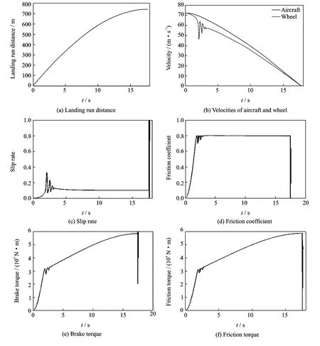
Fig.7 Simulation curves in dry runway case with fuzzy-PID controller
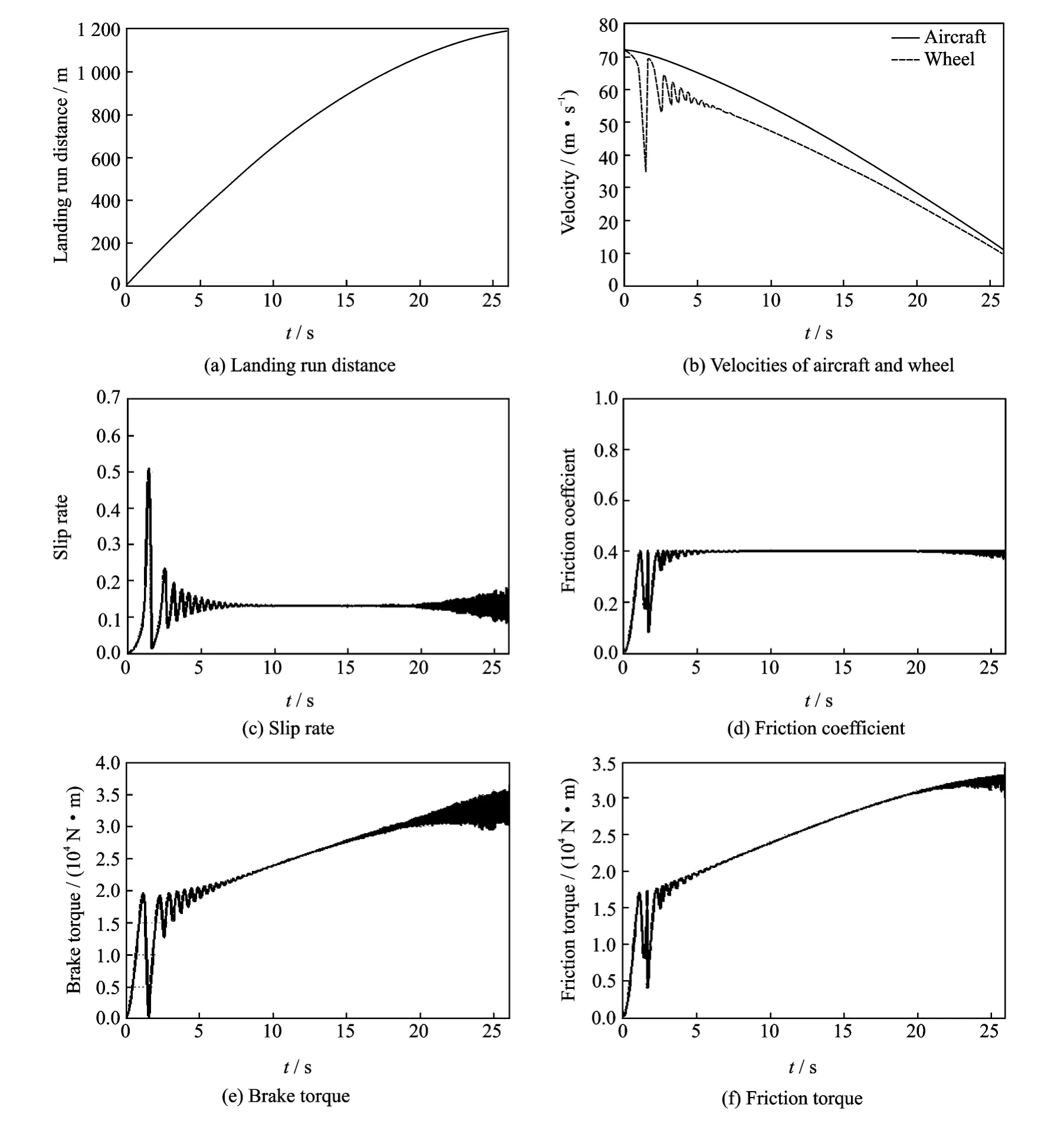
Fig.8 Simulation curves in wet runway case with fuzzy-PID controller
7 Conclusions
(1)The working theory of the slip rate antiskid control system and the electric braking system is analyzed to establish the slip rate control electric braking system.
(2)The electric braking system controller is designed based on the algorithms of the fuzzy-PID control with parameter self-adjustment feature to make the system reach the optimal slip rate at the shortest time and maintain constant,so that the friction coefficient will reach the largest value and the braking efficiency will be increased.
(3)The aircraft ground braking with electric braking system and fuzzy-PID controller is simulated in the two cases of dry runway and wet runway.The results show that the whole system keeps working in the state of stability and high efficiency.
[1] Tang Chuanye.Simulation study of the airplane antiskid braking system[D].Xi′an:Northwestern Polytechnical University,2007.(in Chinese)
[2] Tanner J A.Review of NASA anti-skid braking research[R].SAE 821393,1982.
[3] Stubbs S M.Tanner J A.Review of anti-skid and brake dynamics research[C]//Conference on Aircraft Safety and Operating Problems.Virginia:NASA Langley Research Center,NASA CP-2170,1981:555-568.
[4] Stubbs S M,Tanner J A.Behavior of aircraft antiskid braking systems on dry and wet runway surfaces:A velocity-rate-controlled,pressure-bias-modulated system[R].NASA TN D-8332,1976.
[5] Stubbs S M,Tanner J A,Smith E G.Behavior of aircraft antiskid braking systems on dry and wet runway surfaces:A slip-velocity-controlled,pressure-bias-modulated system[R].NASA TP-1051,1979.
[6] Tanner J A,Stubbs S M.Behavior of aircraft antiskid braking systems on dry and wet runway surfaces:A slip-ratio-controlled systems with ground speed reference from unbraked nose wheel[R].NASA TN D-8455,1977.
[7] Li Huihui.Research of the electric braking system based on the fuzzy control[D].Xi′an:Northwestern Polytechnical University,2003.(in Chinese)
[8] Somakumar R,Chandrasekhar J.Intelligent anti-skid brake controller using a neural network[J].Control Engineering Practice,1999,7:611-621.
[9] Huang You.LQ optimal simulation for aircraft antiskid brake control system[J].Journal of Beijing University of Aeronautics and Astronautics.2003,29(12):1119-1122.(in Chinese)
[10]Wang Jisen.Nonlinear control theory and its application to aircraft anti-skid brake systems[D]. Xi′an:Northwestern Polytechnical University,2001.(in Chinese)
[11]Xie Shihong.MATLAB R2008dynamic simulation of control system instance tutorial[M].Second Edition.Beijing:Chemical Industry Press,2009.(in Chinese)
[12]Wei X H,Liu C L,Song X C,et al.Drop dynamic analysis of half-axle flexible aircraft landing gear[J].Journal of Vibroengineering,2014,16(1):290-298.
[13]Cheng Guangren.Ball screw transmission design[M].Beijing:China Machine Press,1987.(in Chinese)
[14]Ruan Yi,Chen Boshi.Electric drive automatic control system—Motion control system[M].Beijing:China Machine Press,2009.(in Chinese)
猜你喜欢
杂志排行
Transactions of Nanjing University of Aeronautics and Astronautics的其它文章
- Dry Grinding of Titanium Alloy Using Brazed Monolayer cBN Wheels Coated with Graphite Lubricant*
- Multi-objective Optimization of Differential Steering System of Electric Vehicle with Motorized Wheels*
- Compensation Algorithm Based on Estimation State for Transmission Delay in Cooperative Localization*
- Adaptive Angular Velocity Tracking Control of Spacecraft with Dynamic Uncertainties*
- Drag Reducing and Increasing Mechanism on Triangular Riblet Surface*
- Dynamics of Rotor Drop on New Type Catcher Bearing*
